t.jpg)
t.jpg)
Wright J-5C Whirlwind
Wright J-5C CAD Model
by John Riend
Published 2 Dec 2023; Revised 5 Jan 2024
t.jpg)
t.jpg)
Wright J-5C Whirlwind |
AEHS Member John Riend’s Wright J-5C Whirlwind CAD Model |
Wright Whirlwind J-5C Engine 3D CAD Model
J Riend, 29 Nov 2023
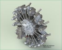
In the close to 100 years since Lindbergh’s transatlantic flight there have been many replicas of the Spirit of St. Louis built to fly or display. I have set out to create a 3D CAD model of the Wright J-5C that powered Lindbergh’s Spirit of St. Louis using the original Wright Aeronautical Division (WAD) drawings that were employed to manufacture these engines.
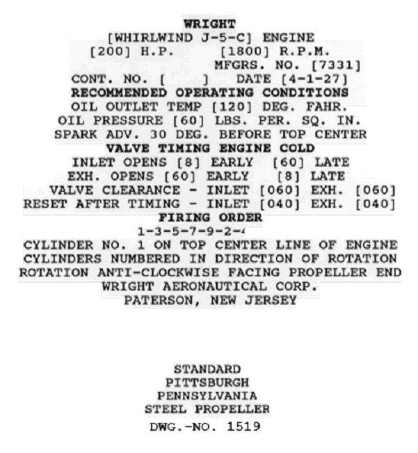
I chose the J-5C because of its notoriety and historical significance notwithstanding the 3D modeling challenge. But before beginning the project (I knew very little about the Whirlwinds history) I wanted to first determine that the Spirits engine was in fact a J-5C. Dr. Bob Van der Linden at NASM was kind enough to respond to my inquiry that the Spirit’s engine was a J-5C and the manufacturer’s is “7331” and sent a copy of the nameplate he had transcribed.
 |
In addition, Brian Niklas of NASM responded to my inquiries on several other J-5C topics and sent a WAD Report titled;
Measurements of Wright Model J-5, No. 7331 After 355 hours of service in Colonel Lindbergh’s Ryan NX-211 “Spirit of Saint Louis”, further confirming the engine model and manufacturing number. (1)
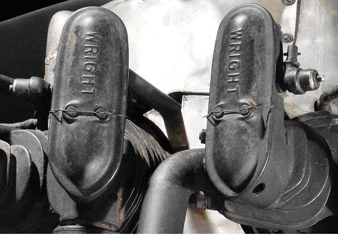
Now that the engine Manufacturing number was settled, I began collecting photos, and reading Journal articles, manuals, etc. about the J-5 engines. One article that caught my eye was page 3 of Kimble McCutcheon’s Wright J-5 “Whirlwind” (AEHS) article that mentioned the spring-loaded grease reservoirs that had been fitted to Lindbergh’s engine. These reservoirs are clearly visible in the Spirit of St. Louis photos on NASM’s webpage (2) and not mentioned in any articles I found regarding the Whirlwind engines.
 |
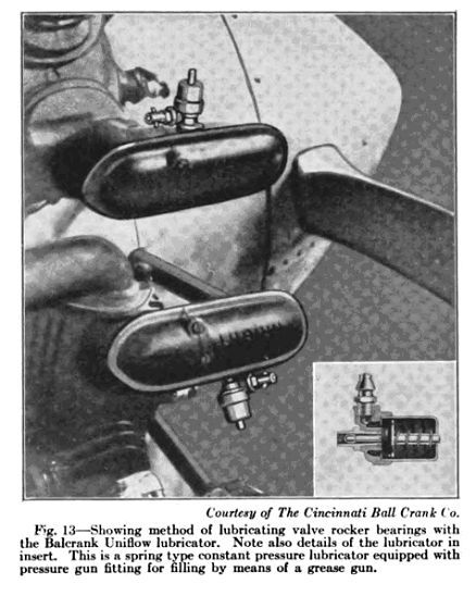
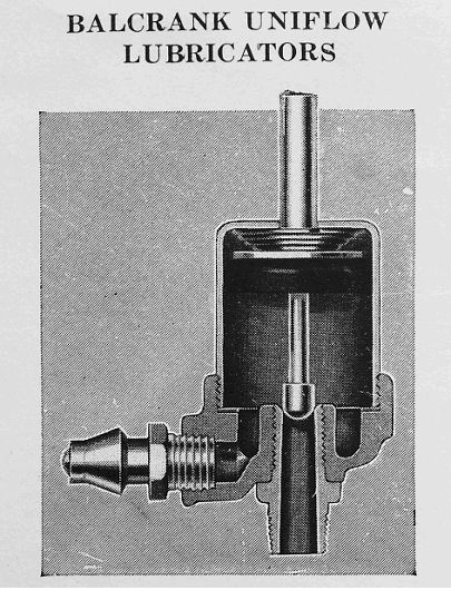
I searched online and found magazine ads for Uniflow Lubricators, manufactured by Balcrank that show the units mounted on a J-5 engine (3). Followed up with Tom Polapink at Rhinebeck Aerodrome and John Norman at JNE Aircraft who both confirmed they had made replicas of the lubricators for their engines and Tom shared his findings on the lubricators he had found as well.
 |
 |
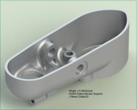
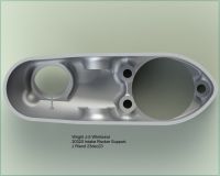
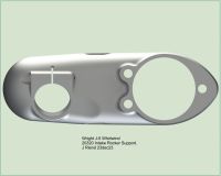
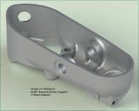
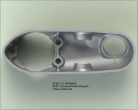
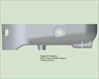
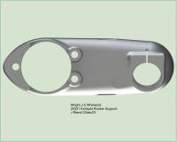
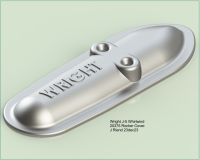
Another item that caught my eye were the Rocker Arm Supports (Rocker Boxes) on the Spirit are not the same design as the ones specified in the Wright J-5C Bill of Material (BOM). I inquired to every source I could think of (NASM, AEHS, Museums, Engine Builders) and nary a clue was had on the differences and continues to be a mystery?
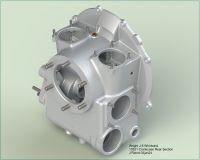
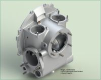
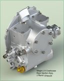
The next task to complete was to collect all of the WAD drawings that specifically cover the J-5C engine. This is my third Curtiss-Wright engine project following the Challenger & Gipsy so I am familiar with the WAD Engine Drawing Archive at Wright State University Library, Special Collections & Archives. Almost all of the Archives drawings are on 1,300 Rolls of Microfilm and there is also a small number of paper drawings. With the assistance of Ms. Jane Wildermuth, Head of Special collections and her staff, I was able to obtain scans of just about all of the J-5C related drawings. There were some disappointments though. Drawings of the J-5’s Main and Rear Crankcase Sections were not filmed and the roll of microfilm the Master and Articulated Connecting Rods were on were lost years ago due to Vinegar Syndrome. Fortunately I found drawings of the Master and Articulated Connecting Rods buried in a 1927 MIT Masters Thesis. I was also able to get scans of the J-4 Main & Rear Crankcases and J-5A-B Rear Crankcase. The only apparent difference in the J-5C Rear Crankcase Section from the J-4 was the Main Crankcase mounting flange. Relying on what I read in WAD Bulletin No. 16, “The Model J-5 crankcase is essentially the same as on preceding models, although it is not interchangeable with any of them. The outstanding improvement is again in the cylinder construction and the valve gear has been entirely altered with a view to greater economy in maintenance. “(4) For the Main Crankcase Section I relied on the J-5C Intermediate Crankcase Section drawing for the front of case differences and the J-5A-B Rear Crankcase drawing for the rear mounting face.
3D modeling most components from 2D drawings is usually pretty straight forward. Modeling 3D castings from drawings that in many cases are hardly readable is a challenge. Usually referring to photographs of the engine is very helpful in relating the 2D drawing design to the actual 3D features. Unfortunately good photos of individual engine castings are quite rare. Fortunately Mr. Steve Curry of Radial Engines Ltd. kindly responded in a big way to my inquiry for any J-5 Crankcase Sections photos he might have. The J-5 castings photos he shared proved very useful in my efforts to complete modeling of the Front and Rear Crankcases but also make some corrections on the Main Crankcase casting.
It as been interesting project, 3D modeling each and every part of the J-5 while all the time imagining how this project would have turned out 97 years ago if they had Computers and CAD back then. It's been a challenge, hope everyone enjoys the models and thinks about starting their own vintage engine project. The WAD Engine Drawing Archive at Wright State University is available to all, and there are Curtiss and Wright Piston and Jet engine drawings just waiting for someone to come dig them out and create a model.
A pdf copy of the WAD 1933 Wright J-5 Whirlwind Parts Manual (Members Section) (5) is available for those that are interested in further research of the J-5. It contains Part Numbers for all J-5 Models with information indicating Serial No./usage where an item is used.
A pdf copy of the WAD Engine Drawing Archive Finding Aid (MS356 Curtiss-Wright Aeronautical Engine Drawing Collection) from the Special Collections and Archives at Wright State University (Members Section) (6). You can find this finding aid online at WSU Libraries but the pdf version is much easier to read and follow.
J Riend, 27 Dec 2023: Discovered two Curtiss-Wright related websites with interesting articles and photographs that shed light on the Wright J-5 Whirlwind manufacturing process (7) and (8).
Rererences:
1. NASM: Measurements of Wright Model J-5, No. 7331 After 355 hours of service in Colonel Lindbergh’s Ryan NX-211 “Spirit of Saint Louis”
2. Ryan NYP Spirit of St. Louis | Smithsonian Institution (si.edu)
3. Balcrank Uniflow Lubricator, Cincinnati Ball Crank Co. Lubrication V14, N7, pg 82, July, 1928
4. http://www.john2031.com/airplane-engines/wright_j-5_whirlwind/information.html
5. Wright J-5 Whirlwind Parts Manual (Members Section).
6. MS-356:Curtiss-Wright Aeronautical Engine Drawing Collection, Wright State University (Members Section).
7. The Paterson Museum Curtiss-Wright and Wright Aeronautical Centennial Exhibit
8. The Passaic County Historical Society Curtiss-Wright Collection
(Using Google, search for Curtiss-Wright site:https://lambertcastle.org/)
Wright J-5C Drawing Quick Reference
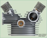
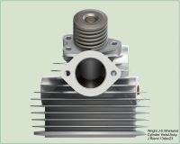
| Crankcase | Crankshaft | Connecting Rods | Cylinder | Valve Mechanism | Cylinder Head | Intake Rocker Support |
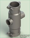
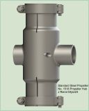
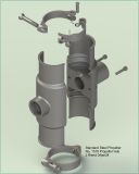
| Exhaust Rocker Support | Oil Pump | Cam Drive | Accessory Drive | Fuel Pump | Propeller Hub |
t.jpg) |
t.jpg) |
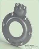 |
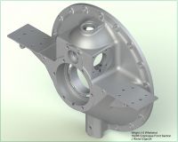 |
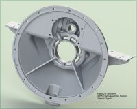 |
| Crankcase Assembly | PN 19640 Front Cover | PN 19295 Front Section | ||
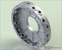 |
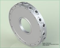 |
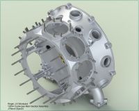 |
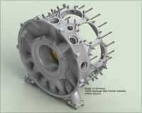 |
| PN 19296 Intermediate Section | PN 13534 Main Section Assembly | ||
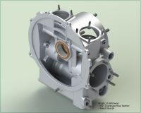 |
 |
 |
 |
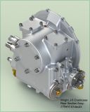 |
| PN 13521 Rear Section | Rear Section Assembly | |||
t.jpg) |
t.jpg) |
t.jpg) |
 |
t.jpg) |
 |
 |
 |
 |
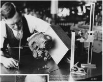 |
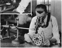
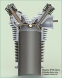
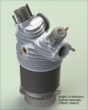
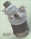
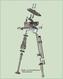
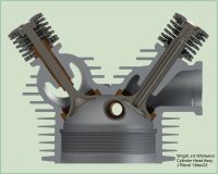
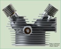
| PN 13527 Cylinder Assembly | Valve Mechanism | Head Measurement | |||
 |
 |
 |
 |
 |
 |
 |
 |
 |
 |
 |
 |
 |
t.jpg) |
t.jpg) |
t.jpg) |
t.jpg) |
t.jpg) |
t.jpg) |
 |
 |
| Cam and Mag Drive | Accessory Drive | PN 19328 Pump Body | PN 13531 Pump Assembly |
 |
 |
 |
 |