Early U.S. Navy Afterburner Development Efforts Part 4c: Westinghouse – A Growing Number of Projects Continue Their Development by Paul J. Christiansen Published 1 Nov 2026
Part 4d: Westinghouse Aviation Gas Turbine Division (in process)
Westinghouse Electric Company, Essington, Pennsylvania
29 June 1949: Contract NOa(s) 10114, XJ40‑WE‑8, Memo regarding Mock-Up Board (MUB) 11 decision. As was decided, the AB would be furnished as part of the engine. Based on their experience with the J34 ejectors, the length was increased by 3", which would occur in the rear tapered section of the ejector. The slope of the tapered section was decreased in order to maintain the previously established ejector exit diameter of 31". The overall length of the engine was now 277 ±2" (23.1 feet!!). The length might have to be adjusted once testing began. The airframe manufacturers were asked to provide the maximum length of ejector their design(s) could handle if adjustment was necessary.
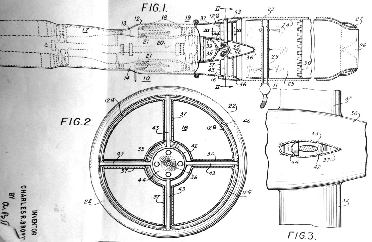
10 July 1949: WAGT Patent Application WM 5014 under Contract NOa(s) 9212. Application shows the attachment of the AB assembly to the turbine housing through use of a ball joint (35 on the diagram) instead of a bellows. This was to reduce the increased stress on a large turbojet (such as the J40‑WE‑8) with an AB that produced flexing in the powerplant. The applicant for WAGT was Charles R. Brown.
Fig. 1. WAGT Invention Drawing of Proposed Improved AB Ball Type Attachment for Large Turbojets Using an AB Instead of a Flexible Bellows. Proposed in a survey for the -32 dated 13 September 1949.
17 August 1949: A revised specification performance curve for the J40‑WE‑8 was given to BuAer for Contract NOa(s) 9212. The primary change was in the specific fuel consumption at high power:
XJ40‑WE‑8 Revised Performance Estimates
Power Setting
Thrust (lb)
SFC (lb/hr/lb)
Take-off (wet)
10,900 (47% Augmentation)
2.48
Military (dry)
7,400 (-1.3%)
0.98
Normal
6,700
0.93
#1 Cruise
6,030
0.90
#2 Cruise
5,025
0.88
Idle
450
4.00
18 August 1949: Monthly Progress Report for July 1949, Report A-882, Contract NOa(s) 9670. Initial testing had continued on the first -32. AB testing total was now 5.21 hours wet, the total engine Military time was 19.52 hours and a total engine program time was now at 78.44 hours. The number 2 engine intended for the 50-hour test was damaged during its green run. Purchasing and parts manufacture for the XJ46‑WE‑2 had been stepped up.
19 August 1949: Monthly Progress Report for July 1949, Report A-883, Contract NOa(s) 9212. Engine XJ40‑WE‑2, serial WE003001, was up to 151.3 hours of testing. Engine XJ40‑WE‑4-1 had completed 195.2 hours of running. The 2nd -4 was complete with a full suite of accessories and was slated to start the 50-hr test the week of 29 August 1949. The first XJ40‑WE‑6 was expected to be ready to test in the latter part of the Fall. Whether this engine would undergo the 150-hr qualification test would hinge on successful completion of the second -4 50-hr test.
30 August 1949: Contract NOa(s) 9670 – Difference between the XJ34‑WE‑32 and -38 Engines. To convert an XJ34‑WE‑32 to a -38 configuration, WAGT stated the following was necessary: Remove from the -32:
1. The AB at the turbine housing aft flange.
2. The fuel lines and control lines to the AB including the AB ignition system.
3. The AB control (which had a built-in fuel filter) and its brackets.
4. The AB fuel pump and air valve.
5. The lead from the electric control cable that was connected to both the AB control and the fuel regulator.
6. The power lever control gear box and its bracket.
7. The bulkhead at the forward turbine housing flange supporting the fuel supply lines to the AB and the thermocouple connection
Add to the -38:
1. Exhaust collector and quick disconnect clamp.
2. Variable area exhaust nozzle assembly.
3. Exhaust nozzle yoke, linkage, and hardware. If the requested change to the nozzle actuator was not approved, additional changes would be necessary.
4. Fuel filter, fuel filter bracket, and connecting hose assemblies.
5. A new lead from the electric control cable to the fuel regulator. (A connector was available on the control cable).
6. A cover for the air valve boss on the air bleed manifold.
7. A new bracket to support the power control lever gearbox.
8. A modified power control lever gearbox (cover, shaft, Geneva wheel removed and a new cover added).
9. Three holes in the firewall used for the AB fuel lines must be plugged.
10. A bulkhead at the forward turbine housing flange to support the thermocouple connectors.
11. Change the relief valve setting in the oil pump to limit the maximum pressure of the high-pressure element
31 August 1949: The exhaust nozzle actuating systems on the XJ40‑WE‑6, -8; XJ46‑WE‑2 and XJ34‑WE‑32 were approved for use on the subject engines. Despite the fact that these systems were not consistent with the requirements, approval was granted because the proposed alternative designs were heavy and complex.
31 August 1949: In response to a Douglas concern regarding the maximum fuel flow supported by the XF4D-1 airplane, WAGT recommended limiting the fuel flow to the engine and AB to that which the XF4D-1 airplane could supply to the XF40‑WE‑8 engine. This would be done with shims in the AB fuel pump to 32,000 lb/hr, the maximum capacity of the airplane's two parallel boost pumps. Such a solution could be used with any fuel supply limited airframe.
13 September 1949: Contract NOa(s) 9670, engine Models -32 and -38, Survey of relocation of the exhaust nozzle actuator and AB flexible joint changes. This proposed that the mounting point for the exhaust nozzle actuator on both the -32 and -38 be moved from the AB diffuser to the aft end of the engine combustion chamber. (Drawing provided not found.) It was also proposed that the AB flexible joint be changed from a bellows type joint located near the aft end of the diffuser to a non-expanding spherical friction joint near the forward flange of the diffuser on the -32. The proposed joint would permit the burner to deflect 2° maximum in any direction about the joint center of rotation. The center would be on the normal AB centerline 10" aft of the diffuser forward flange face. (See Fig. 1 for the patent drawing.)
14 September 1949: Contracts NOa(s) 9670 and NOa(s) 10114, Memo on the analysis of the effects of certain failures in the simplified power control. WAGT stated the original control had placed maximum emphasis on designing the control so that any failure would either have no effect on the fuel flow when the failure occurred or would decrease the flow, both actions protecting the engine. In the simplified control, the addition of a hydraulic overspeed valve in series with the electrically controlled throttle prevented a sudden loss of engine thrust during takeoff conditions. While a description of every possible operation of the power control would take more room than the memo allowed, a generalized description of the five main sections of the power regulator was given.
1. Frequency Meter: This was likened to the “flyweight and speeder” spring combination in a mechanical governor. “There are two sections, one of which acts as a reference, similarly to the speeder spring, while the other is sensitive to changes in frequency, similarly to the flyweights. Of course, a sudden failure of either of the sections will cause a sudden change in engine rpm. However, unlike the mechanical analogy, the most likely type of failure is a change in the rectifier characteristics which will occur gradually and, therefore, cause no sudden change in engine operation. The selenium rectifiers used in the frequency meter have the same order of reliability as the resistors and condensers.” 2. Thermocouple Amplifier: “Probably the most vulnerable part of the temperature amplifier is the vacuum tube. If the vacuum tube heater burns out, the amplifier will go dead and its output voltage will be zero. This indicates to the rest of the power regulator that the engine is running at military turbine outlet temperature. Thus, should such a failure occur when the engine is running at military thrust, the turbine temperature may drift slowly away from the proper value, but no rapid change in engine thrust will occur. However, should the power control be set for any thrust below military when the above failure occurs, the control system will immediately sense an apparent indication of over-temperature and will, by opening the exhaust nozzle, reduce the turbine outlet temperature to the minimum available at the existing engine rpm. No significant change in engine rpm will occur.” 3. Fuel Control Amplifier: If this fails, “…the summation of the error signals is used by a selenium rectifier modulator to modulate an AC carrier signal. The amplitude of the AC carrier is proportional to the DC input voltage, while the phase of the carrier changes through 180 (degrees) when the input DC signal changes sign. Now, since the amplifier is working on the AC signal, the only changes in the amplifier which can cause serious trouble are a large change in gain, a change in phase shift through the amplifier, or introduction of a large hum level. The latter two are bad because the power output stage acts as a phase sensitive amplifier. The output stage gives zero output when it receives no input signal. Now, if the gain of the amplifier goes to zero, as would result from a failure of the voltage amplifier tube, the fuel valve would stay in the position it occupied at the time of failure. A change in the amplifier phase shift, which is a very unlikely type of failure, would in an extreme case cause a reversal in the operation of that section of the control, but would be much more likely to have the effect of decreasing the amplifier gain slightly. The introduction of hum, which might occur as a result of damage to the plate supply filter, can cause erratic operation in an extreme case but is much more likely to cause merely a slight imbalance in the amplifier. The pilot would probably never be conscious of such a failure.” 4. Exhaust Nozzle Control Amplifier: “The effects of failure in the exhaust nozzle control amplifier are essentially the same as in the fuel control amplifier. In fact, the only significant difference between the two amplifiers is in their power output stages.” 5. Power Supply Section: “In the subject power control system the failure situation is very much the same except in the case of the frequency meter and the fuel control circuit.”
16 September 1949: Contract NOa(s) 9670 -32 WAGT Response to Specification Change Request from BuAer. Since additional material and development effort would be required to meet the 50-Hour test procedure as was now redefined in Para 1a of the type specification, the 50-Hour test would be delayed by approximately four months and the cost would be increased approximately $150,000. Two other paragraphs were being revised as requested.
19 September 1949: The Bureau of Aeronautics Resident Representative (BARR) confirmed to BuAer that the data in WAGT’s earlier proposal to simplify the Emergency Fuel System on the XJ46 WE-2 and XJ40‑WE‑8 engines was correct. This involved combining the emergency and primary fuel regulators to save weight and complexity.
21 September 1949: Monthly Progress Report for August 1949, Report A-891, Contract NOa(s) 10114. Purchasing had been stepped up. Delays were being experienced due to material shortages, but a good many of the parts of the AB were in the layout and design state. The first phase AB (fixed tail) was to have been completed but due to the shortages testing would not start until October. Progress as a whole was deemed satisfactory.
22 September 1949: Contract NOa(s) 9212 – Phase II XJ40‑WE‑4 Engine, Qualification test of. Initial testing was complete and after reassembly, the 50-Hour test would begin. The engine had achieved its guarantee of 6,850 lb of thrust at a lower-than-expected turbine out temperature of only 1,255°F versus the predicted 1,425°F. WAGT planned to conduct the 50‑Hour test at a Military thrust of 6,800 lb and asked that the lower turbine out temperature be accepted rather than the maximum predicted temperature. BuAer was asked to affirm acceptance of a guaranteed thrust rather than approving a maximum temperature. The J40 engines to date had not run with an AB attached.
23 September 1949: Monthly Progress Report for August 1949, Report A-889, Contract NOa(s) 9670. The initial -32, built only for development purposes, had 125 hours of running time in total. Of that, 23 hours were at Military settings. The engine had been “plagued with electronic control trouble, cracks in the diffuser bellows and other minor incidences”. High non-burning (dry) thrust losses reflected in the burning (wet) thrust and SFC, were resulting in values below the guaranteed performance. These shortfalls had not yet been resolved. The second -32 engine had completed 20 hours of the 50-Hour test. A compressor blade failure due to fatigue had occurred. The reassembled engine would resume testing on 24 September. Stalling was experienced in the 11,000 – 11,500 rpm range and was being investigated. The completion of the test by 6 October was not expected to be met. The XJ46‑WE‑2 program was gradually being stepped up. A “good many” of the parts still in layout and design were being “pushed” for completion. Some parts manufacture had begun and was being gradually stepped up.
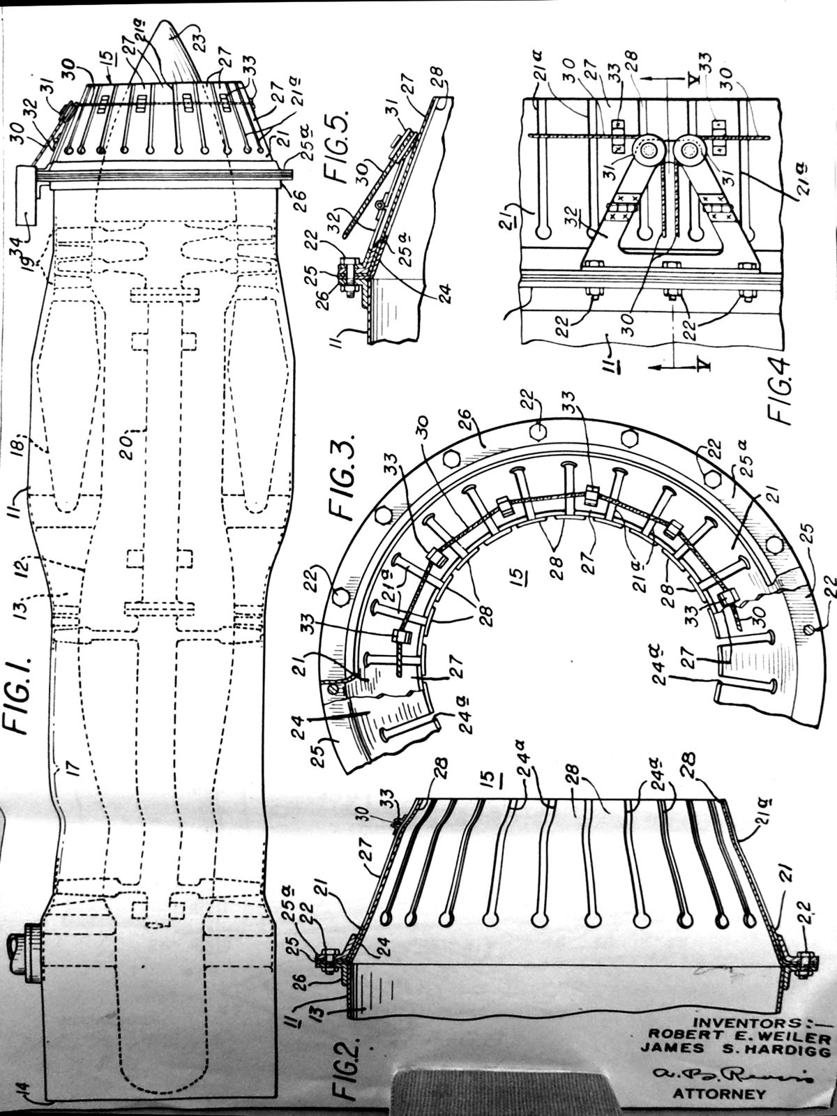
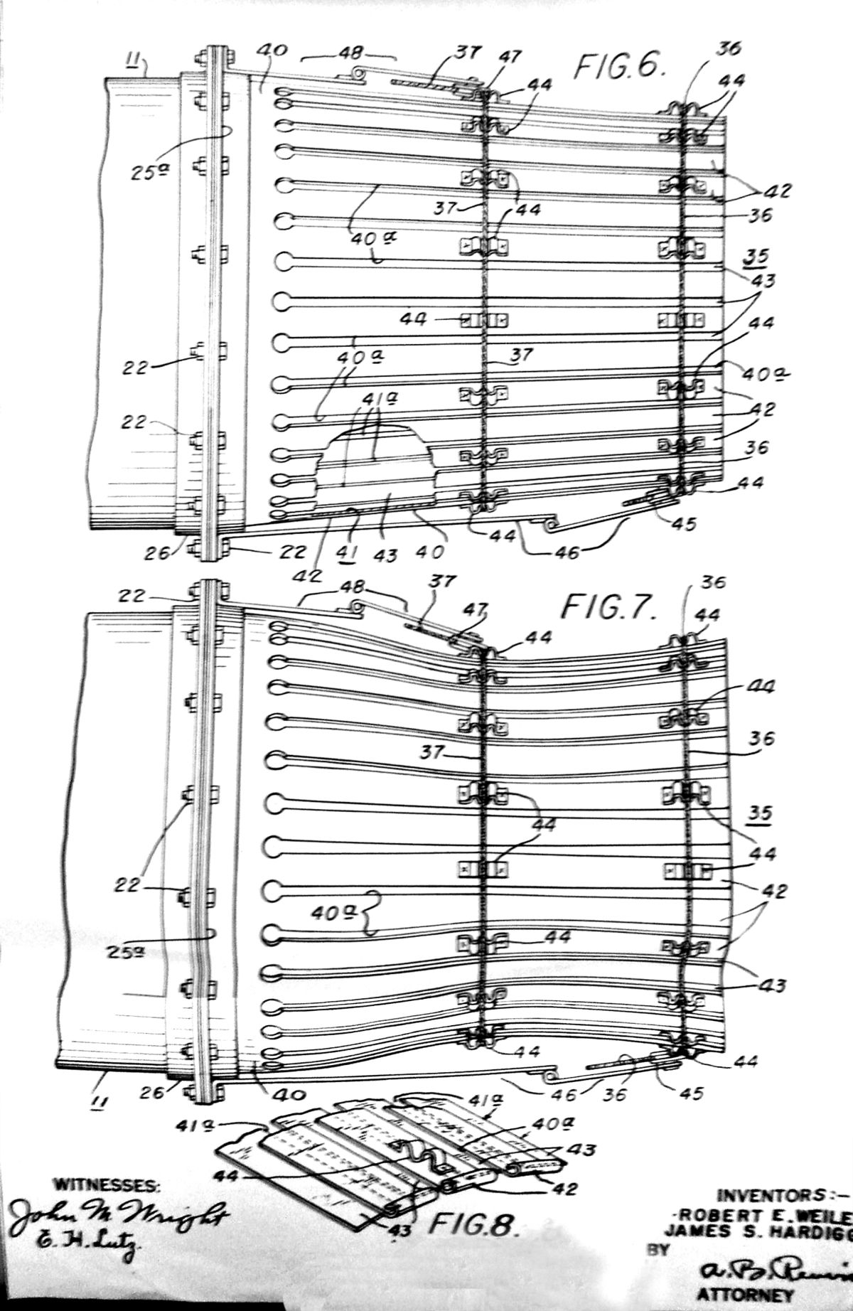
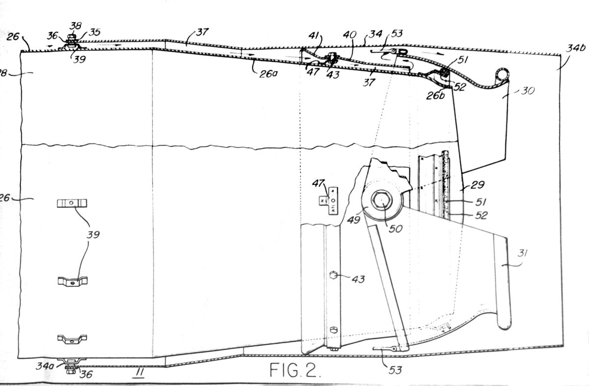
Fig. 2. 26 September 1949 Patent Application WM 5124 by Inventors Robert E. Weiler and James S. Harding for a Wire Controlled, Multiple Petal Variable Exhaust Nozzle Applicable to Gas Turbines With and Without ABs. Submitted under the J40 program Contract NOa(s) 9212.
Fig. 3. More Detail on the Variable Petal Exhaust Nozzle for the J40.
27 September 1949: Monthly Progress Report for August 1949, Report A-892, Contract NOa(s) 9212. The first three engines had been operated without an AB for 346 hours. The third engine destined for the 50-Hour test was an XJ40‑WE‑4 had been operated for 20 hours with satisfactory performance and no mechanical defects. Teardown revealed a deteriorated combustion basket which had caused downstream damage, all repairable. The No. 2 bearing was replaced due to damage from oil fires. The 50-Hour test would start on 27 September 1949. This was to have been completed by 15 September. It was expected the XJ40‑WE‑6 would be ready for testing by the end of the year.
28 September 1949: Convair via the Dallas BARR asked WAGT via the Essington BARR if the -32 could have an electrical signal capable of holding a relay for changing boost pump speed during afterburning provided at the engine junction box without affecting the interchangeability of the engine in other aircraft. A hand written explanation attached states that the increase in fuel flow for the AB reduced the boost pump fuel pressure. They wanted to use a two-speed boost pump and would use a signal to indicate the AB was in operation. (The hand referenced filing notation shows the query was related to Contract NOa(s) 9937 for the XF7U-1.)
30 September 1949: BuAer memo accepting XJ34‑WE‑32 and -38 specification WAGT-24C-8-2D dated 5 April 1949 covering the subject engines in Appendix A. The future Appendix B would cover the production YJ34‑WE‑32 engine and be handled separately.
30 September 1949: Contract NOa(s) 9670 – Memo Discussing Test Plan for 50-Hour Tests of the YJ34‑WE‑32. Due to the current inability of WAGT to resolve the performance deficiencies of the -32, they had proposed delaying YJ34‑WE‑32 engine deliveries, but the Fighter Desk branch of BuAer insisted on deliveries in November due to existing requirements. It was agreed that a 50-Hour test would be run in the near future, this aimed at meeting the original 6 October schedule date. The engines to be shipped starting in November would be functionally the same as the 50-Hour test engine.
6 October 1949: The BARR sent a memo to BuAer adding the following facts in addition to WAGT’s 30 September 1949 memo regarding testing a derated YJ34‑WE‑32 engine.
“The contractor will operate the above engine to peak turbine inlet temperature of 1,525°F corresponding to the measured gas temperature of 1,380°F of the Model Specification during the take-off and military conditions.”
A copy of the 50-Hour test plan was attached. It shows the test was basically an abbreviated standard 150-Hour test plan included in the specification. The specification performance guarantees were listed and these would apply to the first three months of shipments of the YJ34‑WE‑32 engines. Ratings beyond that were not yet decided. A second 50‑Hour test would be run after not more than 26 engines had been delivered.
Specification Performance Ratings for Derated YJ34‑WE‑32 30 September 1949
Rating
Thrust (lb)
RPM
SFC (lb/hr/lb)
Afterburner Operating (Wet)
Take-off (5 Mins)
4,700
12,500
2.60
Military (10 Mins)
4,700
12,500
2.60
Afterburner Not Operating (Dry)
Military (30 Mins)
3,150
12,500
1.20
Normal
3,020
12,500
1.12
Cruise 1
2,720
12,400
1.075
Cruise 2
2,260
12,000
1.04
Idle
205
5,000
5.70
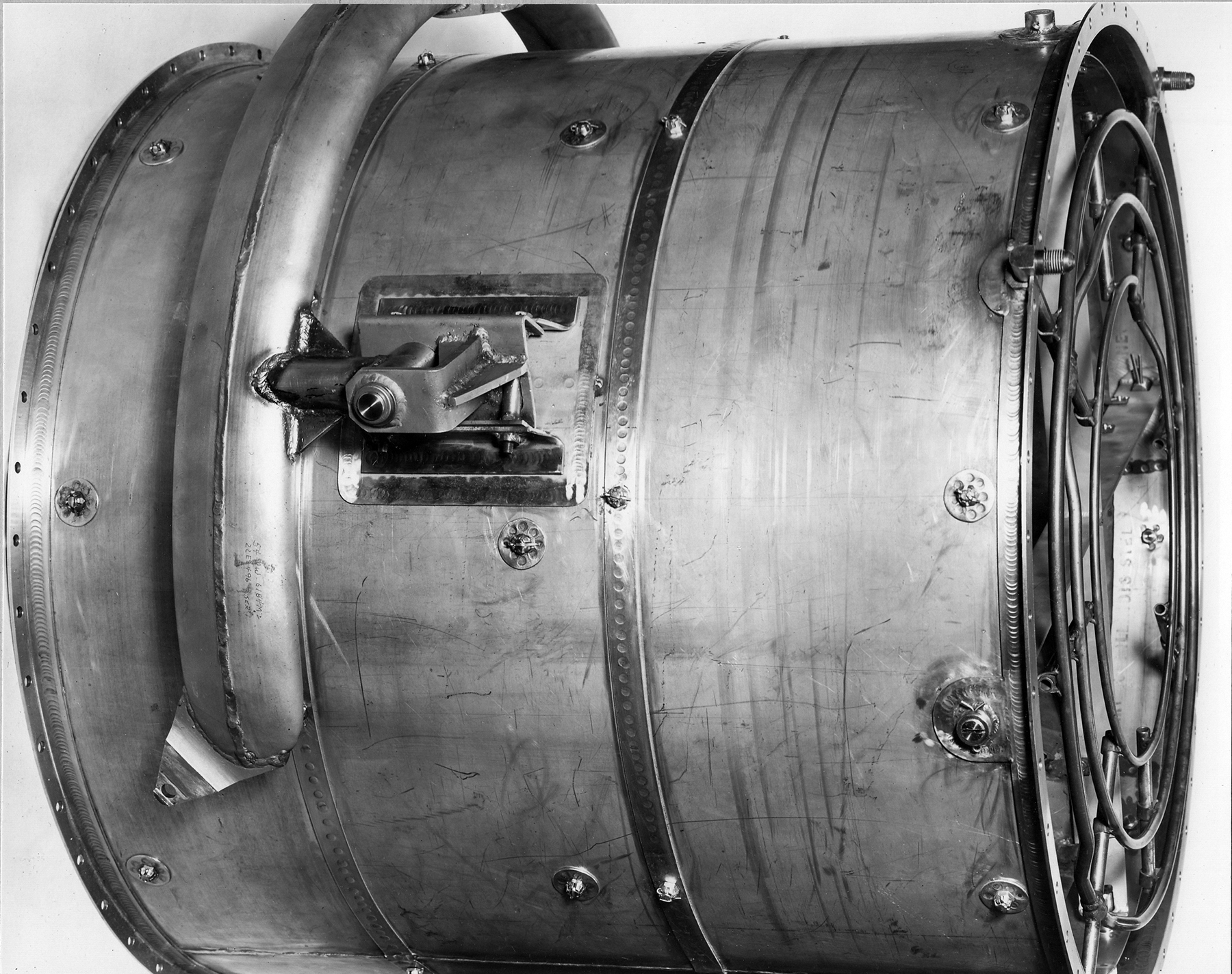
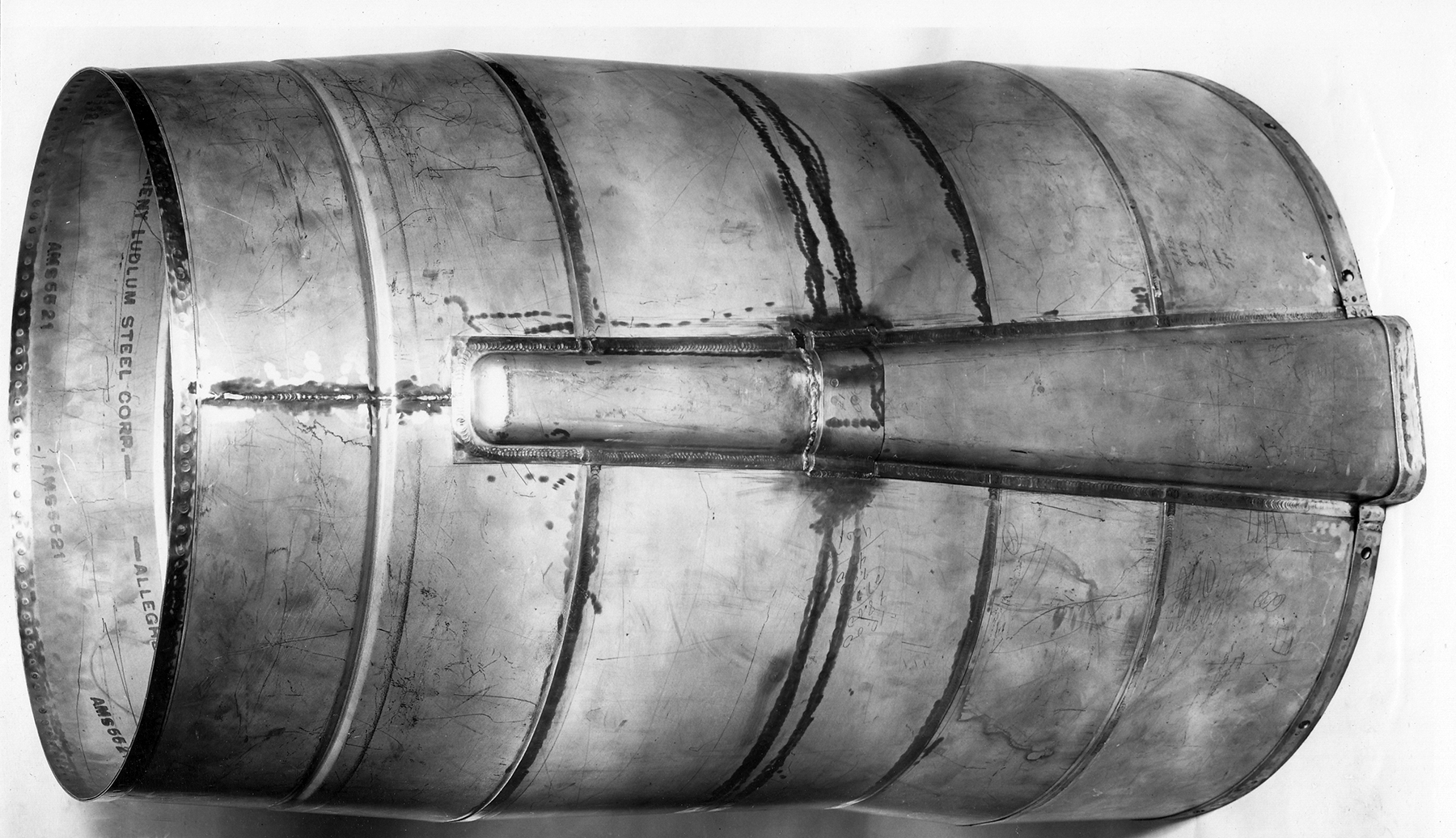
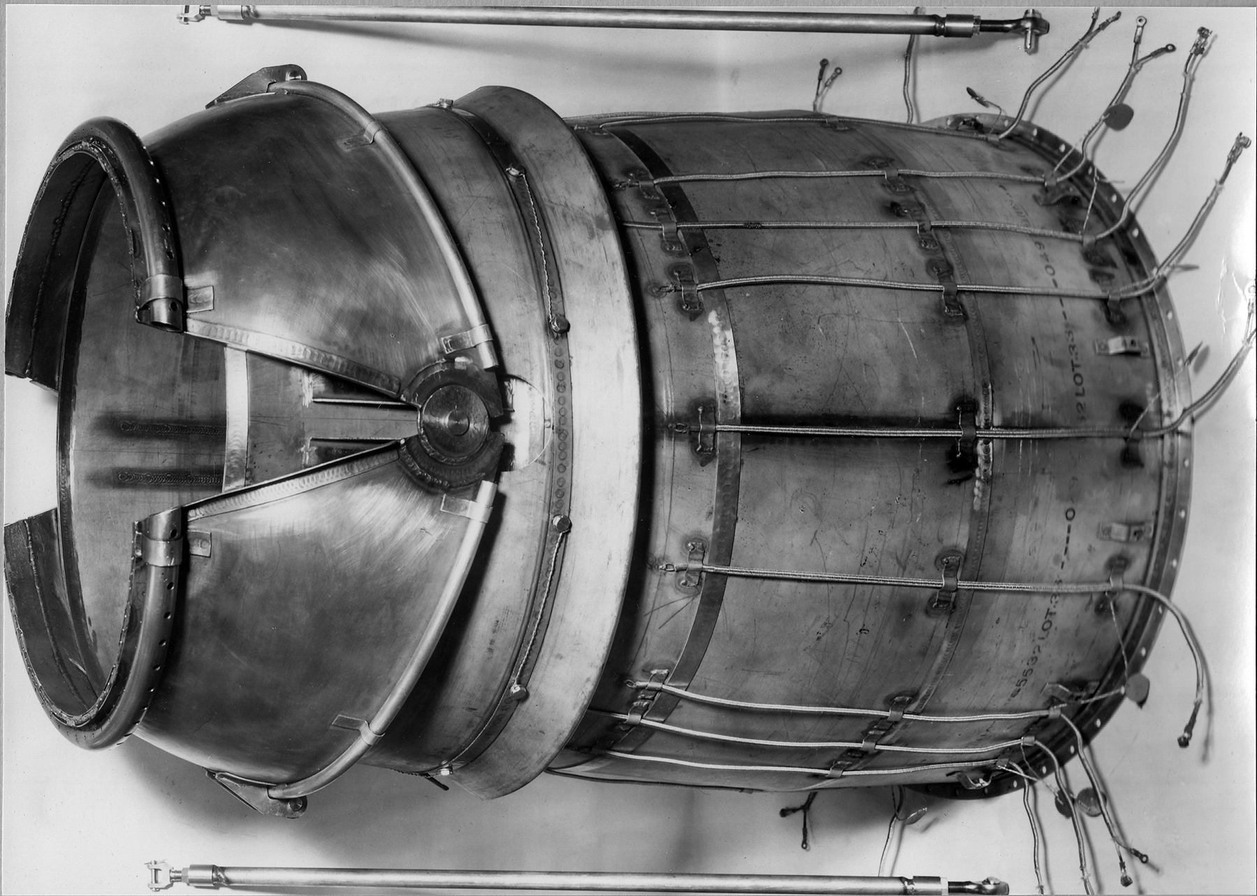
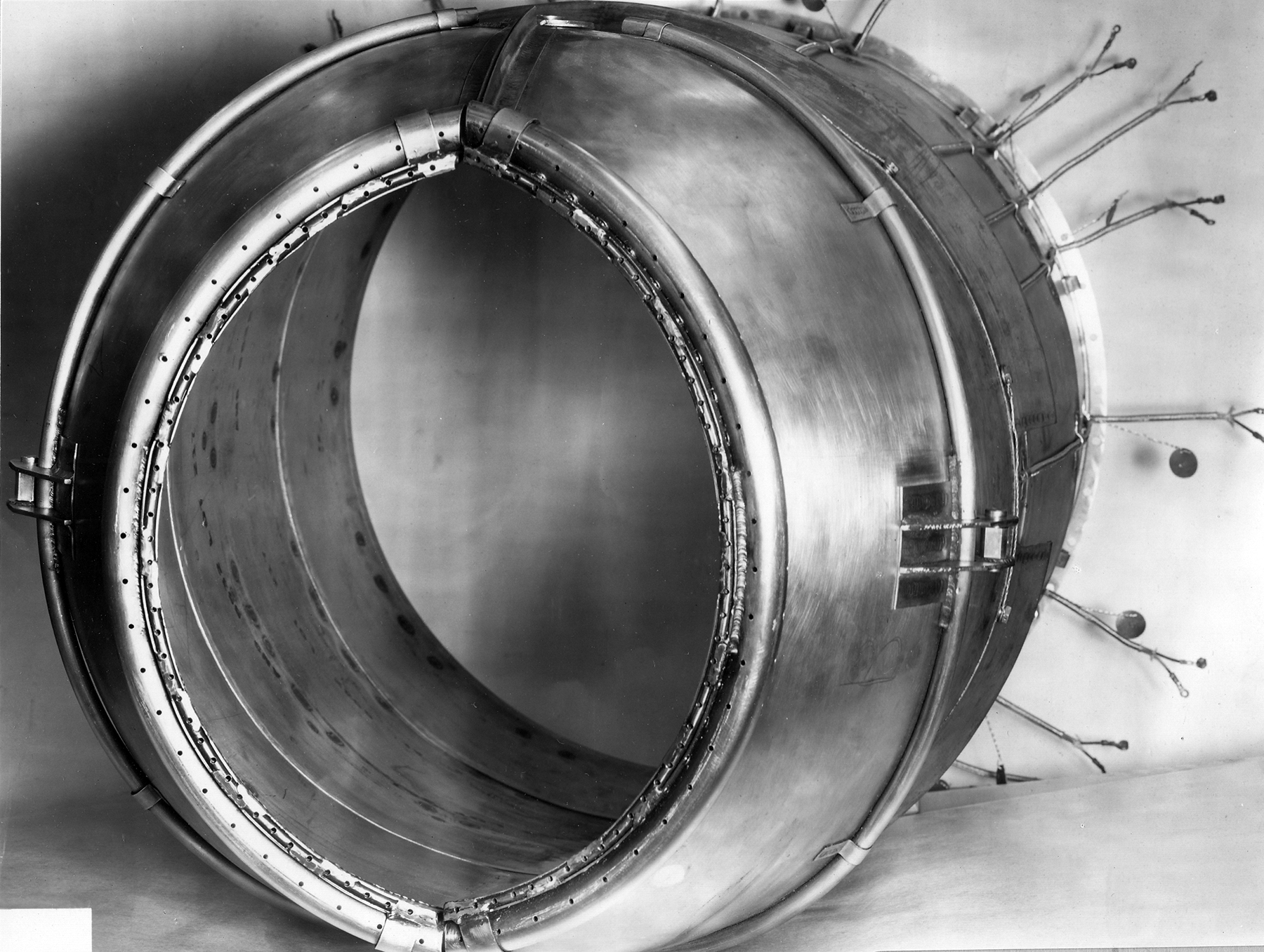
6 October 1949: Various photos taken of the subassemblies making up the -32 AB.
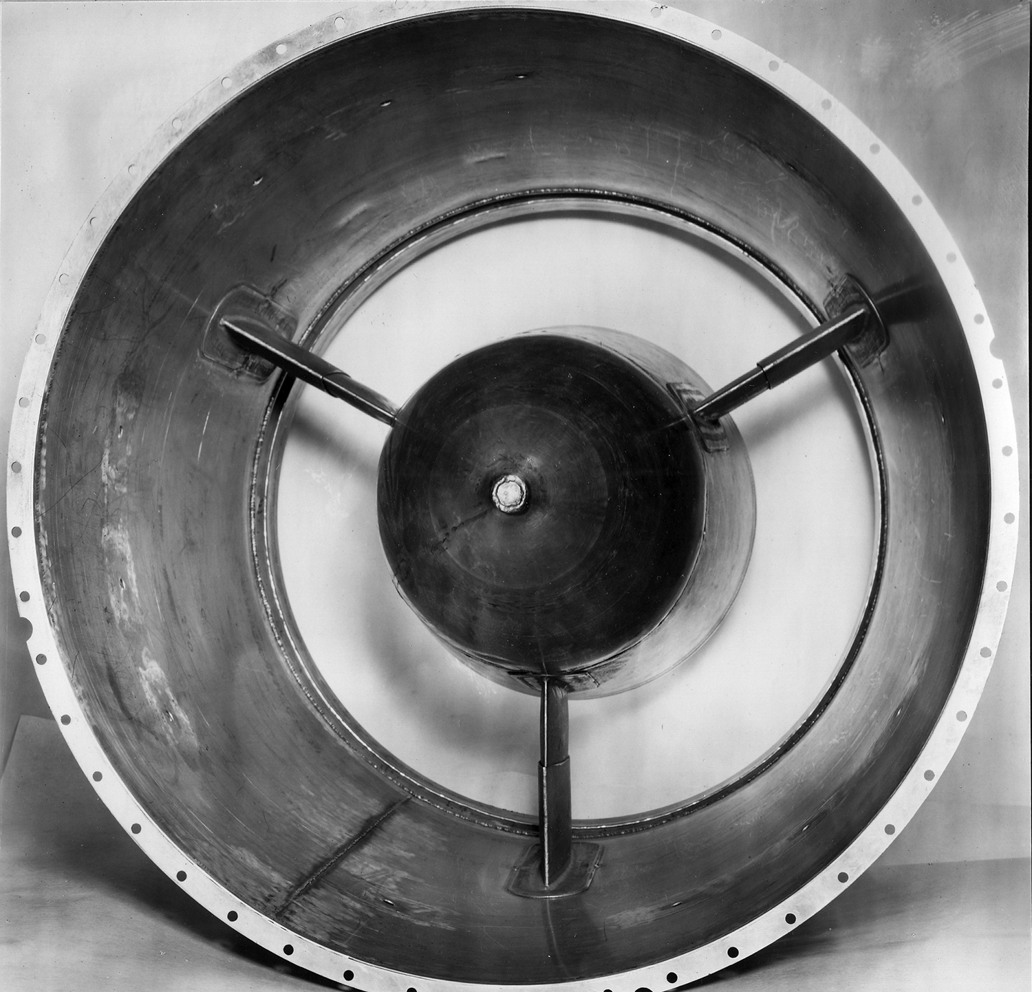
Fig. 4. XJ34‑WE‑32 AB Diffuser Subassembly. WAGT P41610, 6 October 1949. Courtesy Hagley Museum and Library
Fig. 5. XJ34‑WE‑32 AB Combustion Section with Eyelid Yoke Attached. WAGT P41610, 6 October 1949. Courtesy Hagley Museum and Library
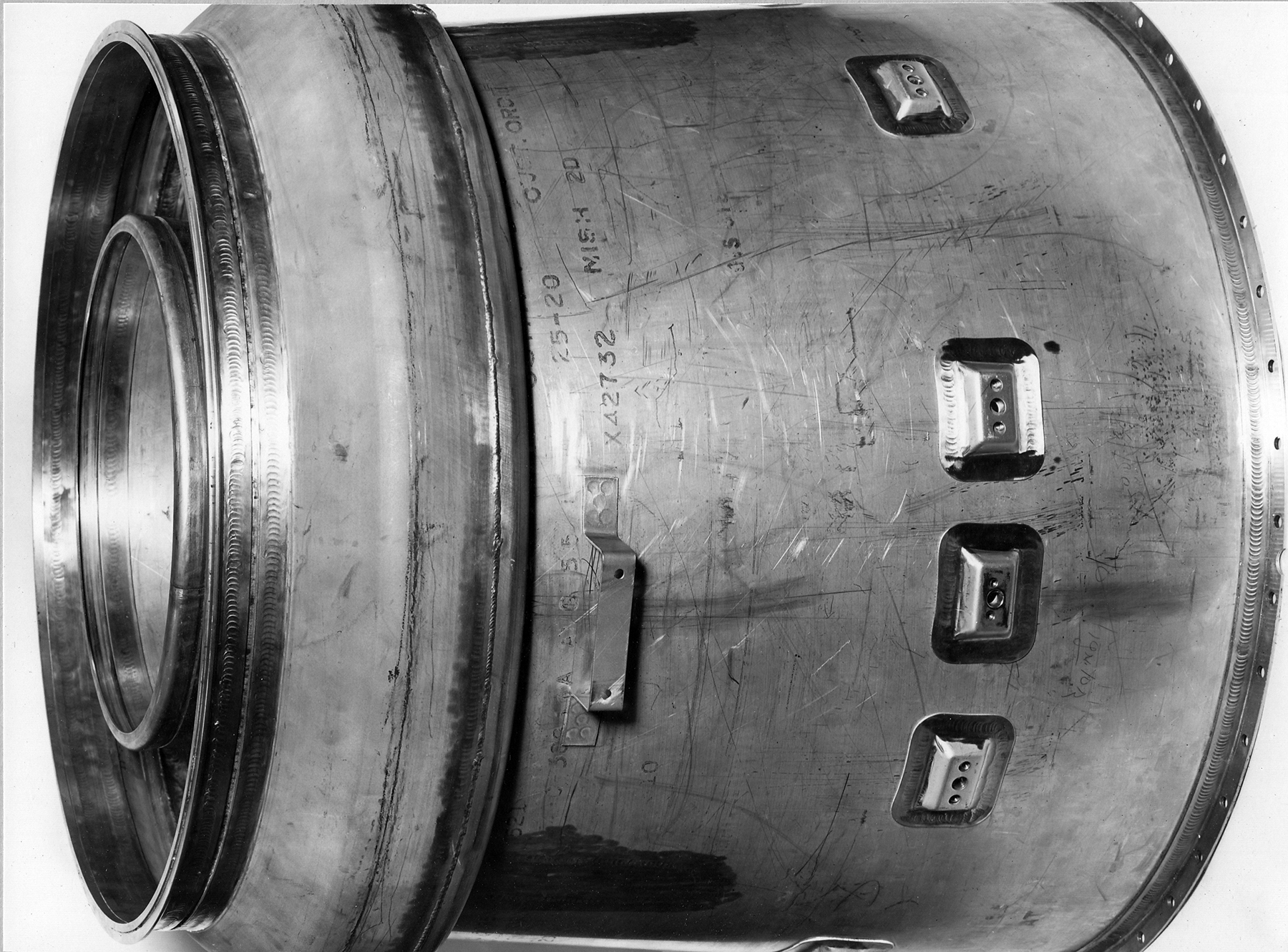
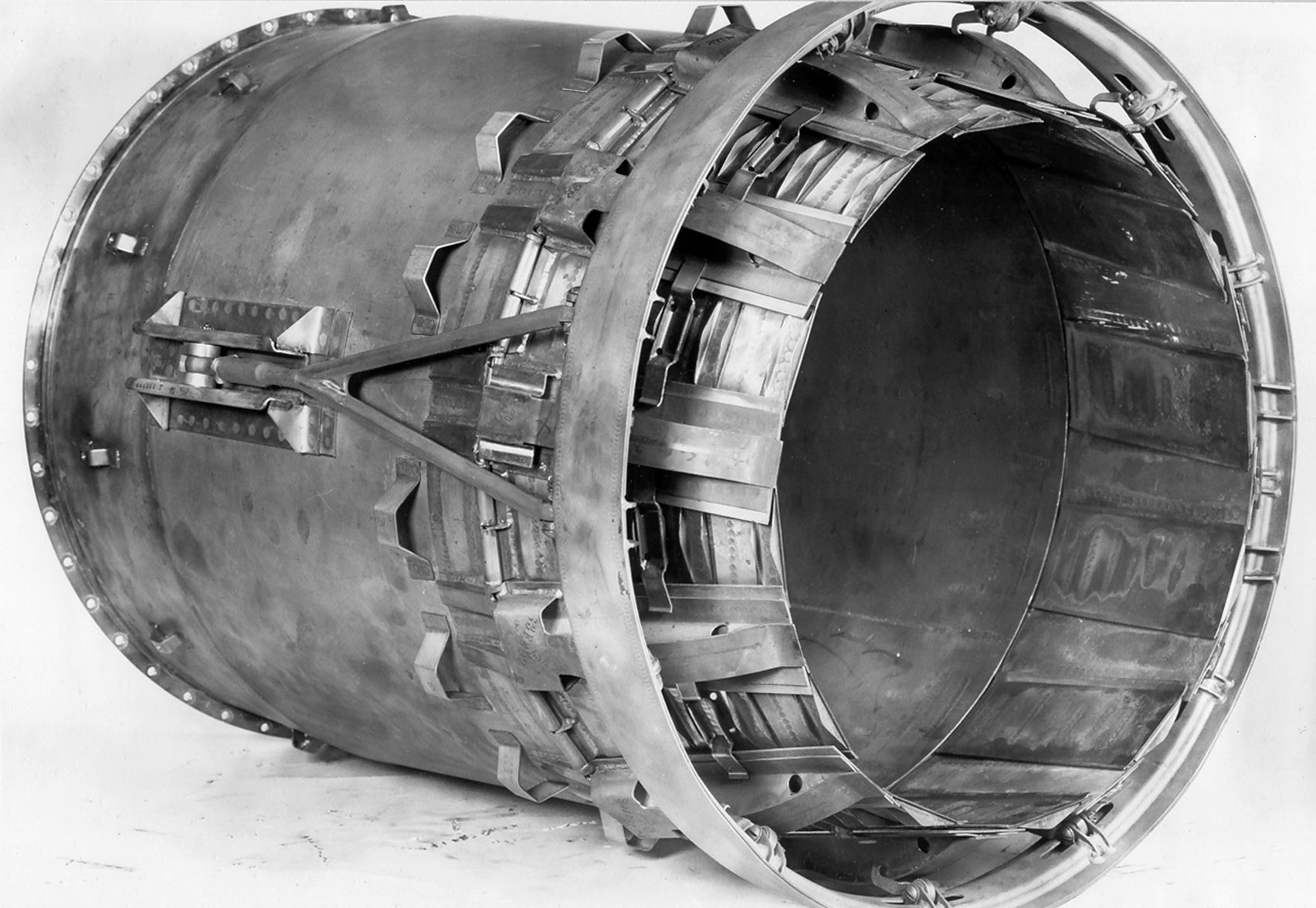
Fig. 6. XJ34‑WE‑32 AB Exhaust Collector External Shell. WAGT P41612, 6 October 1949. Courtesy Hagley Museum and Library
Fig. 7. XJ34‑WE‑32 AB Exhaust Nozzle Assembly with Unattached Eyelid Actuating Rods Visible Top and Bottom, and Thermocouple Leads Attached. WAGT P41613, 6 October 1949. Courtesy Hagley Museum and Library
Fig. 8. XJ34‑WE‑32 AB Exhaust Nozzle Eyelids in Closed Position from Aft End. WAGT P41614, 6 October 1949. Courtesy Hagley Museum and Library
Fig. 9. XJ34‑WE‑32 AB Subassembly Between the Diffuser and Entry to the Combustion Section. WAGT P41615, 6 October 1949. Courtesy Hagley Museum and Library
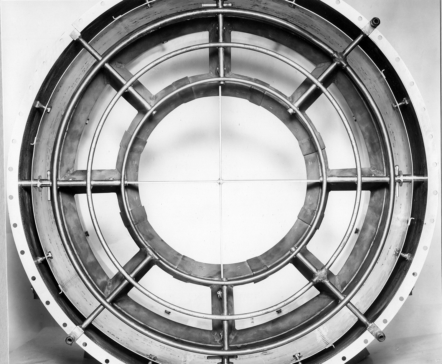
Fig. 10. XJ34‑WE‑32 AB Combustion Section Entry Showing Three Independent Fuel Rings and Matching Flame Holders Below Each. WAGT P41616, 6 October 1949. Courtesy Hagley Museum and Library
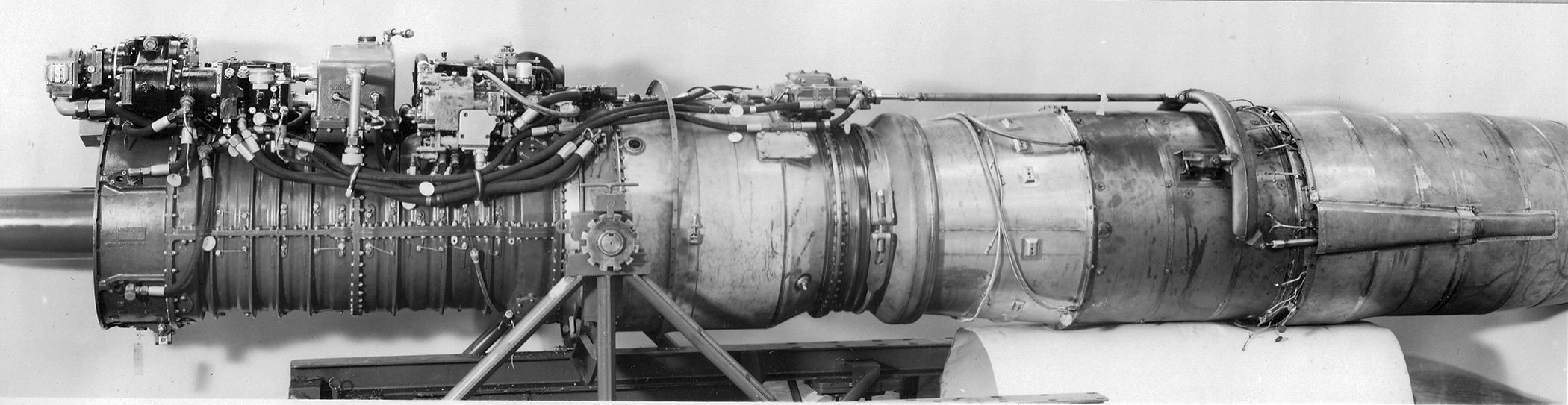
Fig. 11. XJ34‑WE‑32 No. 1 Fully Assembled with AB for Development Testing. WAGT P61667, 20 October 1949. Courtesy Hagley Museum and Library
11 October 1949: Initial Results of First 21 hours of the -32 50-Hour test. Mechanically the engine was satisfactory, generating slightly more than the guaranteed thrust and SFCs lower than guarantee. The electronic control “has functioned surprisingly well.” The test had to be stopped three times due to excessive oil consumption, with different causes in each case. The oil system definitely needed improvement before acceptance would be possible.
11 October 1949: BuAer added the following additional testing requirement to the previously established requirements for the XJ46‑WE‑2 power control qualification test:
“During the conduct of the Endurance Test, Low Temperature Test and High Temperature Test all electrical and electronic equipment shall be vibrated continuously with the frequency varying between 75 and 225 cycles per second at an amplitude of 0.005 inch total excursion, the frequency varying uniformly from 75 to 225 cycles per second and returning to 75 cycles per second on a time schedule appropriately in phase with the power level.”
12 October 1949: BuAer approved the -32 derated YJ34‑WE‑32 50-Hour test schedule with three modifications, each modifying the schedule relative to specific running times for a given power rating and the duration of that cycle.
14 October 1949: Monthly Progress Report on Contract 9212 WAGT Report A-801 for September 1949 for J40 (BARR cover letter only found). The -4 50-Hour test was stopped after 25 hours for reasons reported separately to BuAer by WAGT (not found). A new 50-Hour test would be started at the earliest on 26 October 1949. The -6 was not included in the report, but WAGT was still committed to a -6 test start date of 1 December 1949. The BARR advised reservation since the -6 had to await completion of the 50‑Hour test on the -4 and the fact that complete assembly of the -6 was not possible until later than 1 December due to critical items still coming from suppliers.
17 October 1949: Memo from BuAer on -32 Specification Appendix B, WAGT requirement changes for the derated YJ34‑WE‑32, and acceptance provisions. BuAer stated they would consider specification change approvals after evaluating the results of the 50-Hour test on the YJ34‑WE‑32. Minor changes were pre-approved and the performance table was approved, but WAGT was reminded the changes were temporary and would not be included in the appendix to the specification. The requested deviation on anti-icing due to it not being completely developed prior to the 150-Hour test was accepted on the provision that WAGT agreed to install anti-icing equipment on all YJ34‑WE‑32 engines delivered without anti-icing equipment at no cost to the Government when the equipment became available. Engine acceptance for the YJ34‑WE‑32 was stated as: “In the event that any model YJ34‑WE‑32 engines do not meet the performance requirements of the basic specification, such engines shall be accepted at the convenience of the Government with performance not less than that outlined in reference (a) (table above). Engines so delivered will be returned to the contractor’s plant as soon as practicable for rebuilding to meet the original performance guarantees set forth in the basic specification for the production engine at no cost to the Government.”
18 October 1949: Monthly Progress Report for September 1949, Report A-902, Contract NOa(s) 10114. The fixed nozzle J40‑WE‑8 AB was on hand, but testing was being delayed due to the unavailability of test cells. The XJ40‑WE‑4 would begin its 50-Hour test on 28 October 1949. BuAer’s decision to increase the length of the -8 to ease conversion to the later XJ40‑WE‑10 would have an (unspecified) impact on the delivery date of the XJ40‑WE‑8. BuAer approved the length increase and WAGT’s quote of $1,000 to make the change on 25 October 1949. WAGT informed BuAer on 4 November 1949 that the XJ40‑WE‑10 150-Hour test start date would move to 28 February 1951.
24 October 1949: Monthly Progress Report for September 1949, Report A-899, Contract NOa(s) 9670. The No. 2 -32 50-Hour test engine was being held while its operating system was being tested on engine No. 1 in an effort to resolve control issues. Total running time to date on No. 1 was 145.28 hr/32.70 Military. On No. 2 it was 33.57 hr/4.60 Military. Progress on the XJ46‑WE‑2 engine program was still being gradually stepped up. Some components and parts were being tested.
Fig. 12. Patent Application WM 9052 Drawing Showing Means of Using Air in a Shell to Cool an AB
25 October 1949: BuAer Memo to WAGT stating no funds were available to develop quick disconnect fittings for engine components, although they admitted such disconnects were generally highly desirable. The WAGT proposed program was limited to engine accessories and did not include the AB.
25 October 1949: Patent Application WM 5092 WAGT received authority to submit their Invention Apparatus for a patent regarding the cooling of the afterburner combustion chamber and exhaust nozzle apparatus. The approach was applicable to any of the planned WAGT engines with ABs. The chamber and nozzle had an external metal shell that passed compressor air from the front of the shell to the rear of the nozzle, it then mixing with the AB exhaust. The inventor was Charles R. Brown.
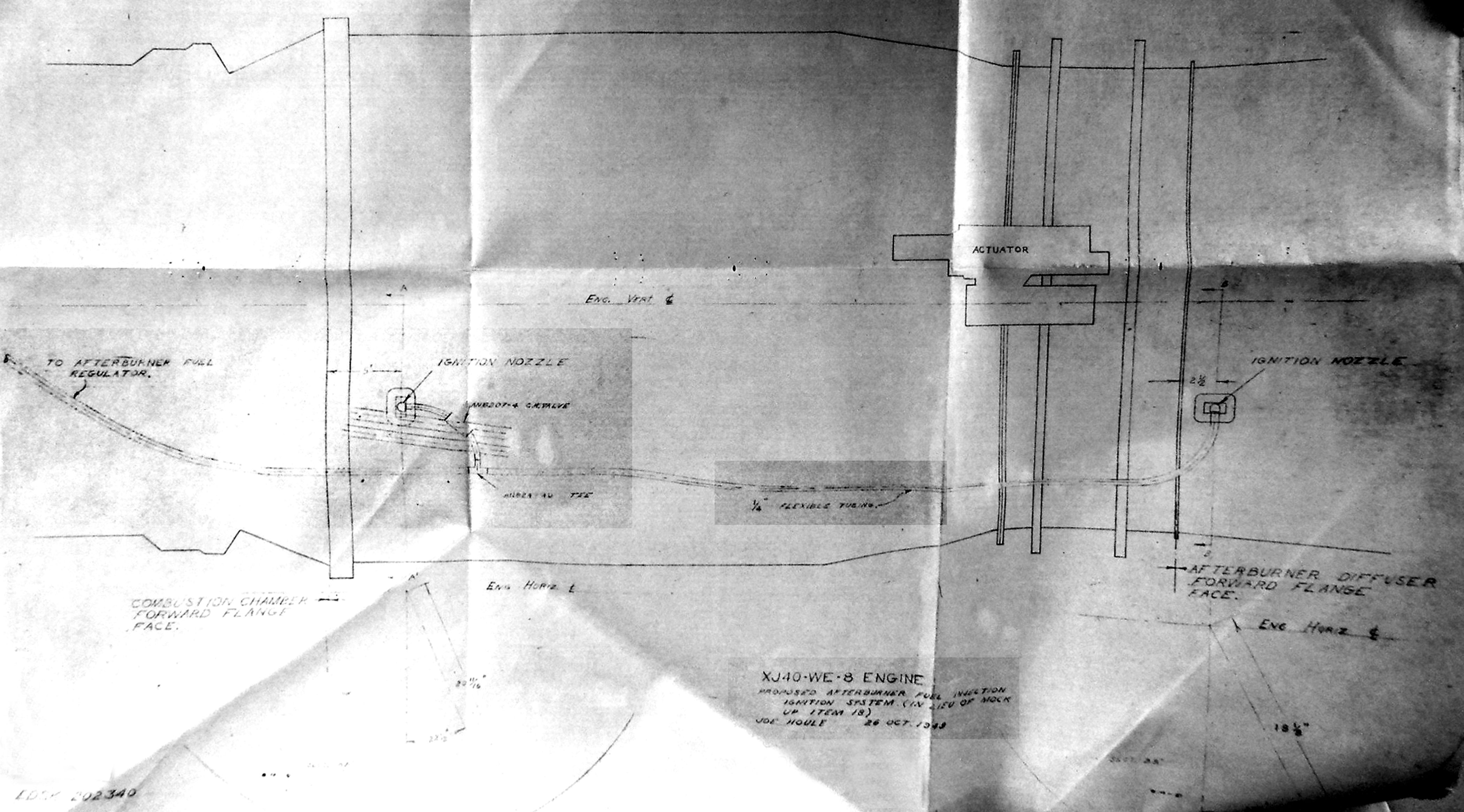
Fig. 13. Badly Faded Line Profile Drawing Attached to the Proposal, Showing the Installation Points for the Hot Streak Ignition on the XJ40‑WE‑8
31 October 1949: WAGT proposed to BuAer the use of a “hot streak” AB ignition system on the XJ40‑WE‑8 in lieu of the current electrical ignition system. The hot streak ignition system “consists of injecting a momentary (approximately 1-2 seconds duration) stream of fuel into the engine combustion chamber at one circumferential point which results in a streak of flame passing through the turbine. This streak of flame is augmented and maintained by the simultaneous injection of additional fuel in the afterburner diffuser section aft of the turbine. This streak of flame ignites the afterburner main fuel supply coming out of that portion of the afterburner fuel manifold in line with it.”
Flight tests on this type of system using J34 engines showed it was superior to the electrical system in many respects, especially at high altitude. Durability over 100 light-offs had been demonstrated with no harmful effects. To implement the change, the ignition control valve would be made an integral part of the AB fuel regulator and be contained within the envelope of that component. The fuel system would be modified with two injection ignitor nozzles, check valves to prevent combustor gas circulation during dry periods and the connecting piping. The installation would eliminate the only two non-engine mounted pieces of equipment on the J40‑WE‑8 engine, namely the AB ignition coil and the high-tension ignition coils. No weight change was anticipated. No price increase was involved on the XJ40‑WE‑8 but increases might be necessary on any future contracts. BuAer approved the proposal on 8 November 1949 pending the results of a survey of the airframe contractors.
1 November 1949: Contract NOa(s) 9670, J34‑WE‑32 and J46‑WE‑2; Contract NOa(s) 10114, J40‑WE‑8. A survey of the desirability of an AB operation electrical signal. A survey was sent out to determine the general desirability of providing a connector on the junction box of the subject engines that would supply the airframe contractor with an electrical signal at the initiation of, and during AB operation.
1. On the J46‑WE‑2 and J40‑WE‑8, the subject signal could be made by adding a single pin connector to the control cable assembly junction box.
2. On the J34‑WE‑32, due to the advanced status of parts releases, a different solution consisting of conversion of the present single pin alternate ignition connector in the AB signal connector by means of internal wiring changes was suggested. If loss of the alternate ignition connector was unacceptable, a change to a two pin could be made without changing the junction box. One pin would carry the alternate ignition connector and the other the AB signal
1 November 1949: Contracts NOa(s) 9212 and 10114, BuAer memo on WAGT change requests in the specifications for XJ40‑WE‑4, -6 and -8 engine weights. Citing of some evidence of an actual weight reduction program at WAGT, evidence with specific recommended components in such a program, was requested. As to the specific reductions requested:
1. On the request for a new weight approval for the XJ40‑WE‑4 and -6 to 3,185 lb and 2,973 lb, these were approved because the -4 was a non-flight engine and the current -6 was an interim engine.
2. On the XJ40‑WE‑8, the request was not approved.
3. The Bureau requested they be provided with a detailed description of the new weight control system “recently established by Westinghouse.”
4. It was requested that engine weight recapitulations be provided as a routine item in all future monthly progress reports on development engines
10 November 1949: BuAer approved Specification WAGT-24C8-2E for the -32 and -38 engines.
17 November 1949: Contract NOa(s) 10114, XJ40‑WE‑8. WAGT sent out a survey proposing the replacement of the electrical ignition system shown at the MUB with the hot streak system proven in J34‑WE‑11 testing. The benefits of eliminating all electrical components and replacement with a simple valve in the hot streak system were covered. Operationally, with hot streak in place, if the AB failed to ignite on the first attempt, the pilot would simply retard the throttle lever to below 92° and then advance it again to 96° to start the AB.
18 November 1949: WAGT was notified that Air Material Command opposed WAGT's proposed change of 13 September 1949 to use of a non-expanding spherical friction joint on the ground; there was concern as to whether the joint could be made tight enough to seal off leakage of fuel and combustible gases during starting and other hot gases thereafter. Clearances tight enough to prevent such leakage would tend to increase the friction in the joint to an extent that would jeopardize its flexibility.
18 November 1949: Contract NOa(s) 9670 for -32, Monthly Progress Report A-919 for October 1949 BARR Summary. The first -32 engine now had 191 running hours. The second engine had 33 hours of running. Control general problems had been parament on the engine and the causes, using the first engine, were being checked out for the 50-Hour test to begin on the second engine. It was unlikely the 50-Hour test could begin in November 1949. The XJ46‑WE‑2 was progressing steadily with purchasing of parts, development of component parts and accessories, and manufacturing of parts steadily going on.
19 November 1949: Contract NOa(s) 9212 for XJ40‑WE‑4, Monthly Progress Report A-911 for October 1949 BARR Summary. The damaged XJ40‑WE‑4 had been rebuilt, put through a green run and was in teardown. Both performance and teardown were satisfactory. Reassembly was in progress with full accessories and the start of the 50-Hour test was planned to be on or about 21 November 1949. Indications were that the 150-Hour Qualification Test of the XJ40‑WE‑6 would not start in December. Not all components were on hand for assembly of the engine. The actual report did not include mention of the manufacturing status of the components for the XJ40‑WE‑6 or mention the overweight statuses that should be in every monthly progress report. WAGT stated they would be in all future reposts once their omission was brought to their attention.
23 November 1949: Contract NOa(s) 10114 – Letter of Intent for Monthly Progress Report A‑912 for October 1949 BARR Summary. WAGT advised BuAer if the decision on incorporating the simplified control system on the XJ40‑WE-8 was not made shortly, it could cause unavoidable delays on the fuel booster pump and possibly other components. Some components of the engine were still in layout and design stages. Some had been released for manufacture. Not all components for the -8 gearbox had been started on and the BARR expected the 15 February 1950 delivery of the first gearbox to be late. The actual full report included a full discussion of the weight problem on the XJ40‑WE‑8 (not found.)
Fig. 14. Patent Application WM 5209 Drawing Fig. 1 for a New Way of Supplying Fuel to the AB Without a Fuel Pump
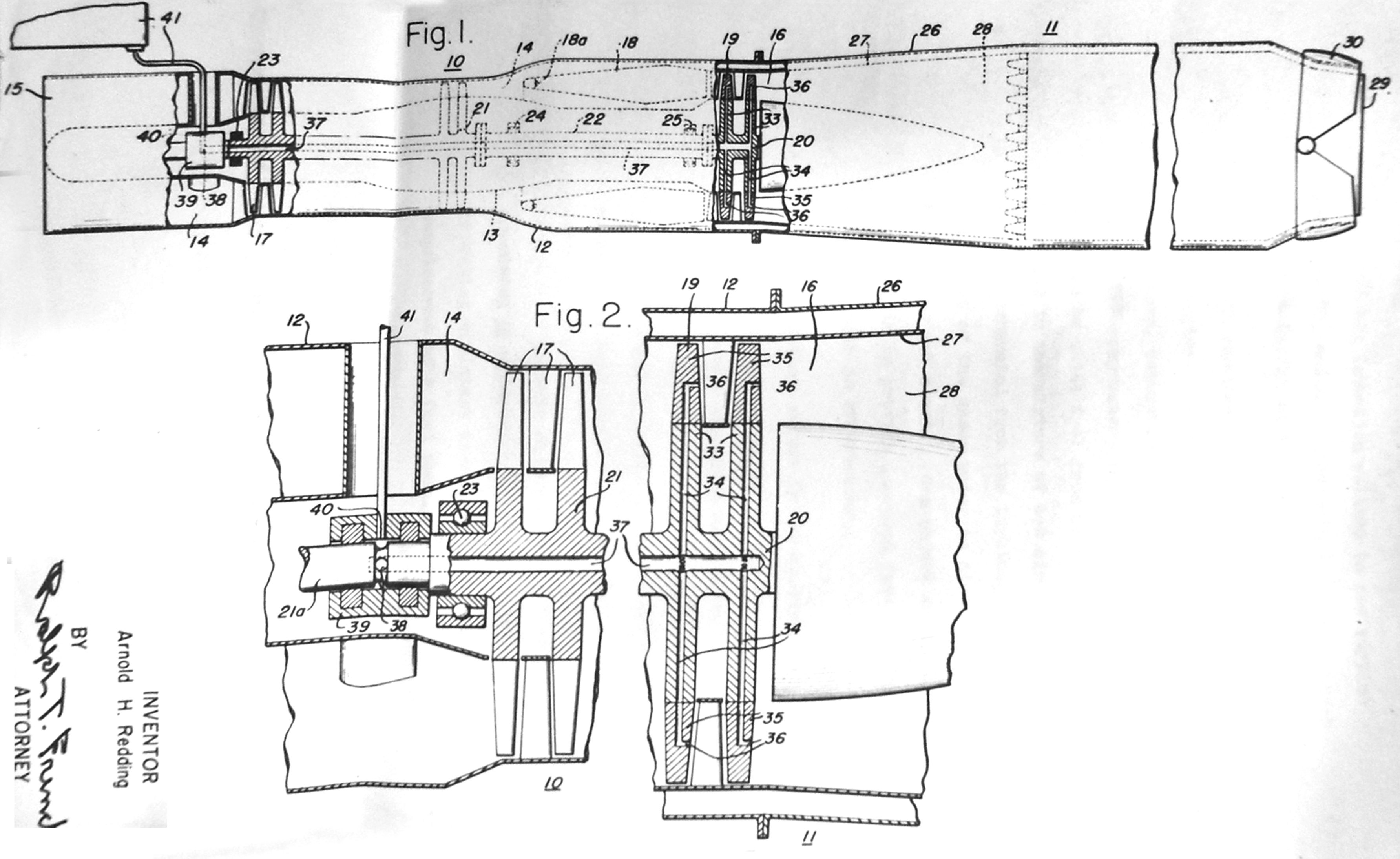
25 November 1949: Contract NOa(s) 9670, Patent Application WM 5209, Applicant Arnold H. Redding. This was a patent application presenting a new way of supplying fuel to the AB without the use of fuel rings made of tubes and their supports in the gas flow from the turbine. The fuel would be delivered through internal channels inside the turbine blades, these leading to ports for the fuel to escape. Discussion of the need for flame holders was not addressed, nor the impacts of on/off cooling on the turbine blade life. The invention reads:
“According to the invention, the turbine rotor 20 constitutes the means for introducing fuel into the afterburner apparatus 11, and comprises discs 33, each having a multi-branched passage 34 and carrying a plurality of radial vanes 35 in which are formed discharge passages and orifices 36 which communicate with the passage 34. Extending though the shaft 22 and the compressor rotor 21 is a fuel supply passage 37, which communicates with the passage 34 in the turbine disc. The forward and of bearing shaft 21a of the compressor rotor 21 extending beyond the adjacent bearing 23 has formed therein a laterally disposed inlet port and annular groove 38 communicating with the passage 37. Mounted in slip-sealed relation with respect to the shaft 21a is a stationary annular collar member 39 have a port 40 through which fuel can be supplied to the inlet port 38 from a suitable fuel source, generally indicated at 41.” (See Application Fig. 1.)
(Author’s comment: Although such an arrangement would eliminate the need for an AB fuel pump since centrifugal force would pull the fuel down and out, it would appear the fuel control valves so far away from AB would introduce a large delay in AB startup waiting for fuel, and on AB shutdown demand, a delay in actual cessation of AB burning would occur.)
1 December 1949: WAGT advised BuAer that the proposed simplified emergency fuel system for the XJ J40‑WE‑8 could also be developed and used on the XJ46‑WE‑2 engine for a combined cost of $29,495 which included a fixed fee of $1,930.
1 December 1949: BuAer asked WAGT for more information on the newly proposed AB connection in lieu of a flexible type before granting approval.
1. How the new joint would operate to take care of expansion of the AB longitudinally and radially.
2. How the joint remained gas tight during all conditions.
3. Was there adequate flexibility during the highest friction loads to assure proper functioning of the joint?
Also, BuAer suggested that a larger sketch of a cross section of the joint with the pertinent notes and without dimension would enable a more rapid diagnosis of the operation of the joint by BuAer.
1 December 1949: WAGT informed BuAer that since BuAer had disapproved an interim method of providing an AB operation signal on the -32 and a survey had been sent to the airframe contractors asking their opinion of the need for such a signal on all AB equipped engines, WAGT was not at that time taking any further action on the subject.
2 December 1949: BARR memo to BuAer updating -32 testing status. Engine No. 1 was wrecked at approximately 200 running hours due to a suspected oil cooler leak that let gasoline fuel enter the No. 2 and No. 3 bearings, causing failure. The turbine shaft and turbine were also damaged. The damage to No.1 engine meant the No. 2 engine would now have to be used to check out controls instead of the No. 1 as planned. The start of the 50-Hour test on the -32 would not begin until the latter part of December.
6 December 1949: The BARR forwarded WAGT’s response to BuAer’s query on possible costs associated with requiring the J46‑WE‑2 to be tested to the new MIL spec MIL-E-5007 to 5010 specifications. WAGT estimated the additional cost would be $694,503 which included the fixed fee of $45,435. Additionally, there would be a six-month extension on the delivery of the remaining XJ46‑WE‑2 items. The change in the severity of the tests affected the items with limited life at high temperature, these were now being required to be tested to two and a half times as much required operation at limiting temperature. Accelerations that were apt to cause severe distortion would be four times as many as the prior specification. WAGT noted they were planning to use a test to failure approach, then redesign of the weak or failed part, beginning with the current engine, rather than one of a total redesign from scratch which would add weight throughout the engine, much of it proving unnecessary in the end.
9 December 1949: The Bell Aircraft Corporation responded to the AB signal survey and noted that the information did not clarify if the signal was only an indication of throttle position, fuel flow or temperature. If approved, the single pin solution on the J46 was acceptable.
16 December 1949: The Douglas Aircraft Company’s response to the AB signal survey stated that the proposed solution would only show the AB should be operating and not if it actually was. They recommended a temperature-based signal be used and shared they were investigating a high temperature probe manufactured by the Eclipse-Pioneer Co.
16 December 1949: WAGT proposed (AGT-52 dated 12 December 1949 (Not found)) that a short stack AB be developed and qualified for the J46‑WE‑2. The bid specification was based on BuAer acceptance of prior proposals for development to MIL-E-5009 specification and development of the simplified emergency fuel system.
19 December 1949: The Contract NOa(s) 9670 BARR forwarded WAGT’s memo of 12 December 1949. This described the deviations from the production -32 variant at the time the 50-Hour test engine was wrecked due to the No. 2 and No. 3 bearings failing. Twenty-five (25) variations from the production design were noted across the engine, of which four were related to the AB:
1. Turbine Rotor Housing – AB Diffuser Junction: The test unit incorporated a single spigot point at that quick-disconnect point whereas the production unit would incorporate a double spigot joint for improved AB diffuser alignment and roundness.
2. AB Assembly – The test unit AB had a ball joint seal of 0.032" material, an inner fuel ring and middle fuel ring of smaller tube diameter, and an adapter cone and tube welded into the nozzle gates to reduce the effective area whereas the production unit would have a more flexible ball joint seal of 0.021" material, stronger inner and middle fuel rings and a smoother nozzle gate of correct area.
3. AB Fuel Control – The AB fuel control had been altered to be functionally the same as the production engine, however, the test unit differed in casting contour, seal drain boss detail, and other minor respects.
4. AB Quick Disconnect Clamp – The clamp was of lighter construction planned for the first 10 production engines. Engines following the first 10 would have a sturdier clamp already released
WAGT’s expressed opinion was that the listed differences were “minor only” and that the durability expected of the test engine would be similar to or less than that expected of the production units.
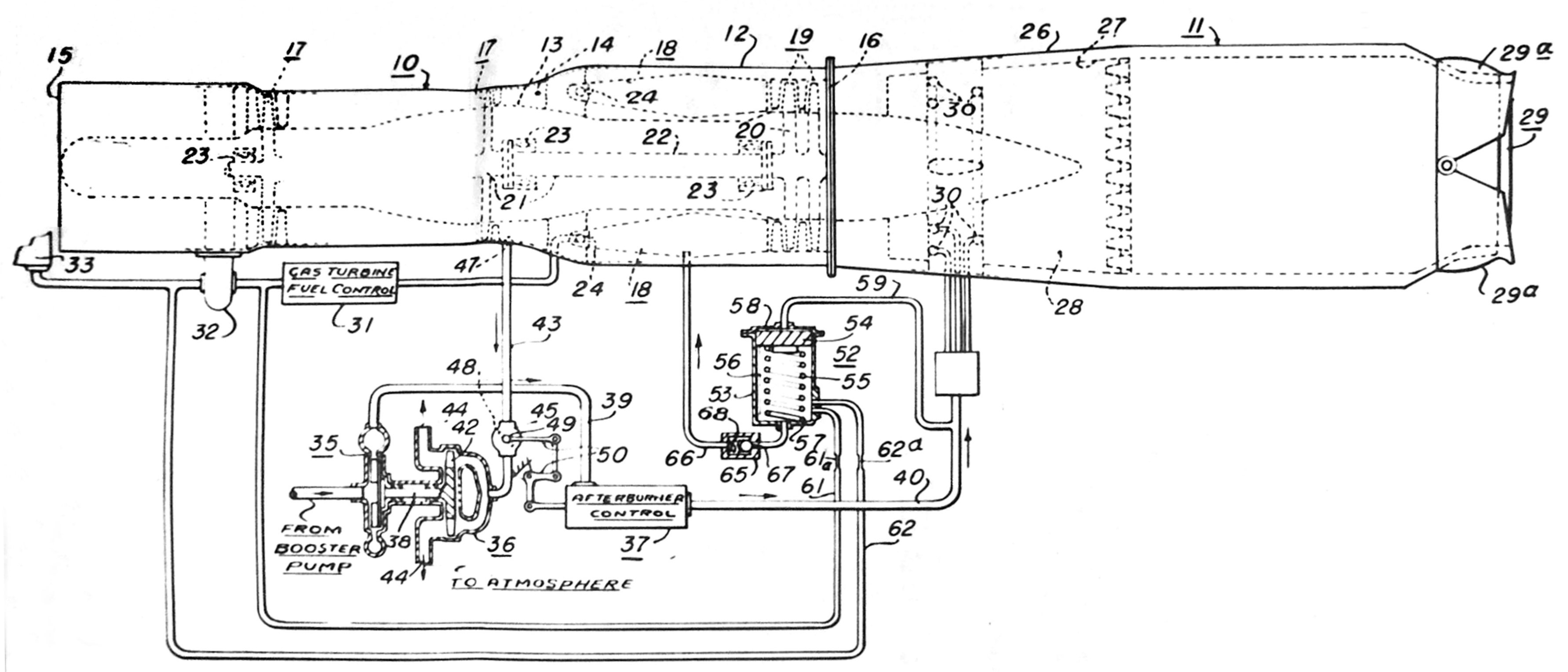
19 December 1949: Request for approval to file Patent Application WM 5219, dated 4 November 1949. This was for the invention of hot streak AB ignition.
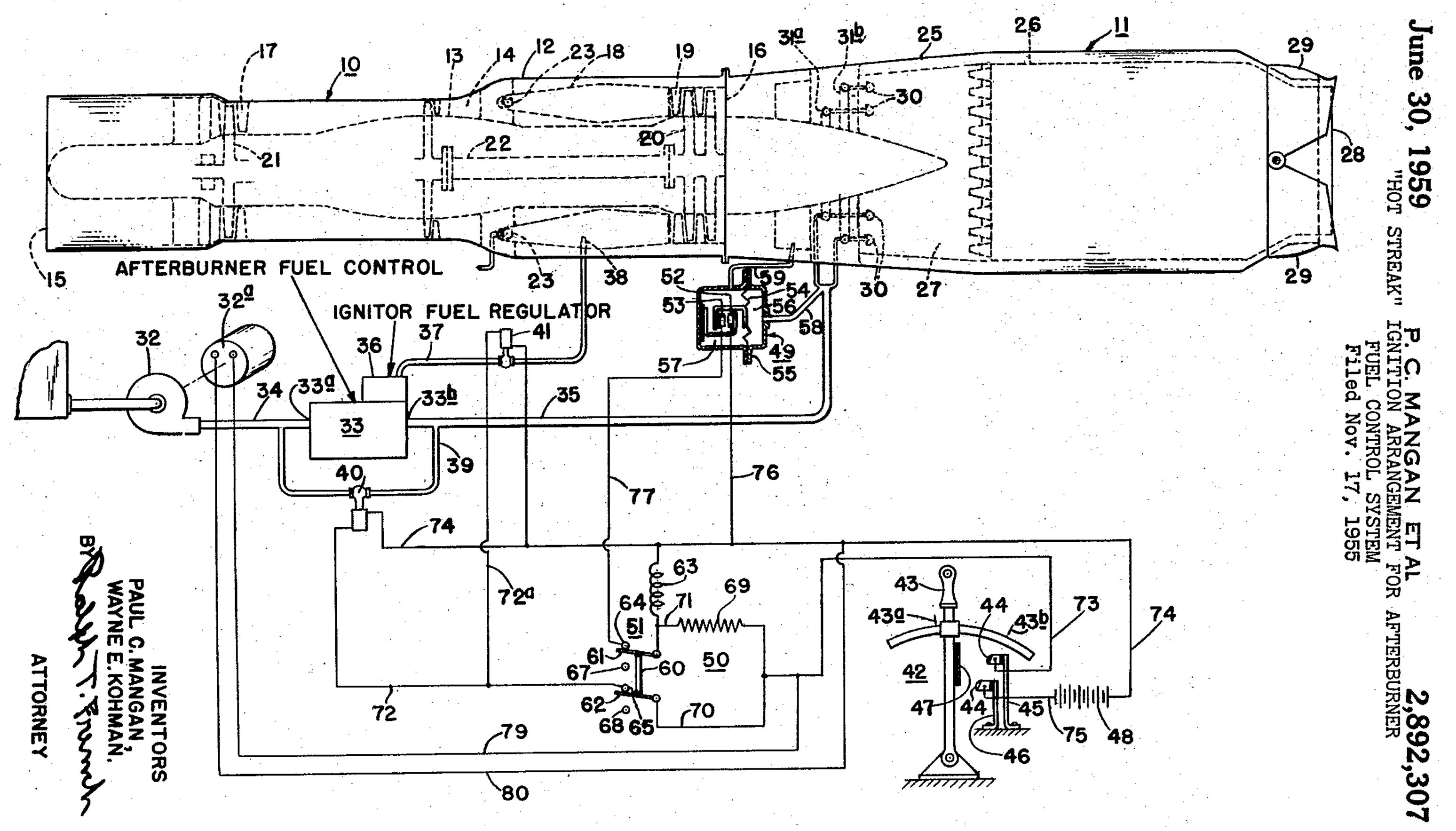
Fig. 15a. Patent Application WM 5219 Artwork. The drawing is notional and not to scale. The hot streak injection source is number 38 in the drawing, showing fuel going into the combustion chamber(s) before the turbine. Patent No. 2,640,316 was awarded 2 June 1953.
Fig. 15b. Patent Application WM 5042 Updated Hot Streak System, Paul C. Mangan and Wayne E. Kohman inventors. Improved control system. Filed on November 17, 1955. Patent No. US 547577A was awarded 30 June 1959.
21 December 1949: WAGT Memo on XJ34‑WE‑32 Engine Afterburner Flexible Connection. WAGT provided a description of the flexible (ball joint) connection they were using on the -32 to help answer U.S. Army concerns. The attached engineering drawing with its reference numbering was not found. WAGT noted that since the connection was virtually a non-expanding spherical joint, allowances for axial expansion of the AB had to be provided in the design of the airframe AB mounting system. The flexible joint was designed to permit the AB a deflection of two (2) degrees maximum in any direction, considered to be the maximum encountered in any airframe application. Any frictional moments were within the allowable for engine parts.
23 December 1949: Contract 9670 XJ34‑WE‑32 Monthly Progress Report for November 1949, Report A-916, BARR Summary. The 50-Hour test had not been started and the intended start date had not yet been predicted. The control system was still giving trouble. If the problem(s) were resolved, the test would begin on 30 December 1949. Progress on the XJ46‑WE‑2 was not mentioned.
27 December 1949: Contract NOa(s) 10114 for XJ40‑WE‑8 Monthly Progress Report for November 1949, Report A-919, BARR Summary. Some components were in redesign because of weight reduction. The fixed tail AB that was on hand for the last five weeks, had been piped and was ready for testing. The qualification of the XJ40‑WE-4 was in the test house and had priority. No other test house was available.
29 December 1949: Contract NOa(s) 9212 for XJ34‑WE‑32 Monthly Progress Report for November 1949, Report A-920, BARR Summary. The XJ40‑WE‑4 50-Hour test was stopped after 11 hours after turbine damage was discovered. The engine was repaired and sent back to the test house and the test resumed from the point where it was stopped.
4 January 1950: BuAer approved the relocation of the exhaust nozzle actuator on the -32 and ‑38 engines, having found that the relocation was beneficial to all airframe manufacturers except Douglas for the MX-656 (Douglas X-3). BuAer recommended to the Army that Douglas be requested to investigate a more suitable location for the MX-656.
5 January 1950: XJ40‑WE‑4 50-Hour Test Update. The test was completed on 3 January 1950. The spark plugs, electronic control and the second stage turbine blades would require further qualification. Tear down was about to begin.
11 January 1950: -32 50-Hour Test Information Update Memo. The turbine failure of 7 January 1950 was found to have been caused by a faulty outer nozzle ring. The ring was oversize which permitted the nozzle outer shroud to rotate, this causing the vanes to drop out. Damage was sustained by the first stage turbine blades and first stage nozzles. (The word “nozzles” was used by WAGT to describe the guide vanes just before each of the turbine rotor stages.) Engine No. 1 (WE023001) was being reassembled into X24C8-3 and then prepared for the 50‑Hour qualification test. Removing the engine from the production line would delay delivery of the J34‑WE‑32 engines for Contract NOa(s) 9791 (the production -32, 34, -36 and -38 contract).
13 January 1950: BuAer officially accepted the ball joint flexible connection for the XJ34‑WE‑32 but subject to satisfactory test and operation.
19 January 1950: Contract NOa(s) 10114 for XJ40‑WE‑8 Monthly Progress Report for December 1949, Report A-927, BARR Summary. Only the 2 Phase I fixed tail ABs were on hand, testing of which would begin by the end of January. Everything else was in layout stage, being improved in design or undergoing changes for weight reduction.
20 January 1950: The Chief of BuAer warned WAGT that, while BuAer was interested in the simplified engine control proposed by WAGT for the XJ46‑WE‑2 and XJ40‑WE‑8 engines, lack of funds was preventing BuAer from authorizing its development. WAGT should not make any assumptions that such development authorization would be made and asked them to review their designs for dependency on such a system being developed and available. Any failure of their engine designs in test without such a system would not be considered justification for delays. A serious effort should be made to plan for successful completion of the engine projects without the proposed system.
20 January 1950: Contract NOa(s) 9670 - BARR memo asking BuAer’s attention to the second paragraph in WAGT’s memo of 16 January 1950. This explained the AB thrust boost requirements of the J34‑WE‑32 compared to the XJ34‑WE‑11 engine being developed under contract NOa(s) 5382. BuAer had pointed out that both ABs used a cooling ejector. This indicates lack of adequate cooling for the -32 AB was being experienced at that time, among other things. The higher the combustion temperature that could be handled, the higher the boost that could be achieved. From 16 January 1950 WAGT memo, paragraph 2:
“The engine designed with an afterburner on Contract NOa(s) 5382, XJ34‑WE‑11, was guaranteed to have a thrust that was 30% higher than the basic engine, the J34‑WE‑30, to which it was added. The J34‑WE‑32 engine is guaranteed to have 40% boost over the basic engine. The afterburners are quite similar. It was possible to obtain the 30% boost on the -11 afterburner but it has not yet been possible to achieve the 40% required on the -32 afterburner.”
At a conference held on 9 January 1950, the efforts to improve the -32 AB were described in some detail. It was agreed that by 25 January 1950, WAGT would advise BuAer of the performance that could be met with the -32 AB in its present configuration. (No minutes from this conference have been located.)
20 January 1950: Contract 9670 XJ34‑WE‑32 Monthly Progress Report for December 1949, Report A-923, BARR Summary. The 50-Hour test on the -32 had not yet begun. The engine was undergoing final testing. It was experiencing high vibration and the turbine was found to be out of balance. This was corrected. Control trouble on the -38 was being experienced. Qualification testing of accessories was underway for both engines. The dual fuel pump was strengthened with a higher core strength spline after a failure of the part. The pumping system testing would be continued. The XJ46‑WE‑2 was progressing satisfactorily. Manufacturing, purchasing and testing were moving forward rapidly. Full engine testing was expected to begin in March 1950. (For some reason, WAGT Progress Reports for the month January 1950 are not in most of the relative contract files. They appear again for February 1950 and later.)
26 January 1950: Contract NOa(s) 10114 WAGT Memo regarding the engine fuel pump requirements of the XJ40‑WE‑8 and its accessibility. WAGT, contingent upon a control system that was in accordance with the XJ40‑WE‑40 specification, suggested that the fuel inlet configuration be changed to provide a single aircraft fuel inlet configuration on the engine for both engine and AB fuel. The fuel booster pump would supply fuel to both the engine dual fuel pump and the AB fuel pump. It was felt the lowering of the AB pump fuel inlet pressure requirements through the furnishing of fuel to the inlet of the high speed, single stage centrifugal AB pump for a separate slower speed low pressure booster pump would provide superior performance compared to the arrangement that added low pressure pump stages on the AB pump high speed shaft. The change added an estimated 4 lb to the engine weight. The cost would be absorbed by WAGT. An Appendix B attached to the memo, “Study of Fuel Inlet Pressure Requirements for the XJ40‑WE‑8.” shows that the originally planned low pressure line pumps were susceptible to cavitation when boiling fuel vapors were present. At the rate of climb of an airframe with the XJ40‑WE‑8 this was a risk on hot days. The move to tank mounted booster pumps would avoid the cavitation risk as tank vapors were vented overboard in the event of boiling and not drawn into the pumps.
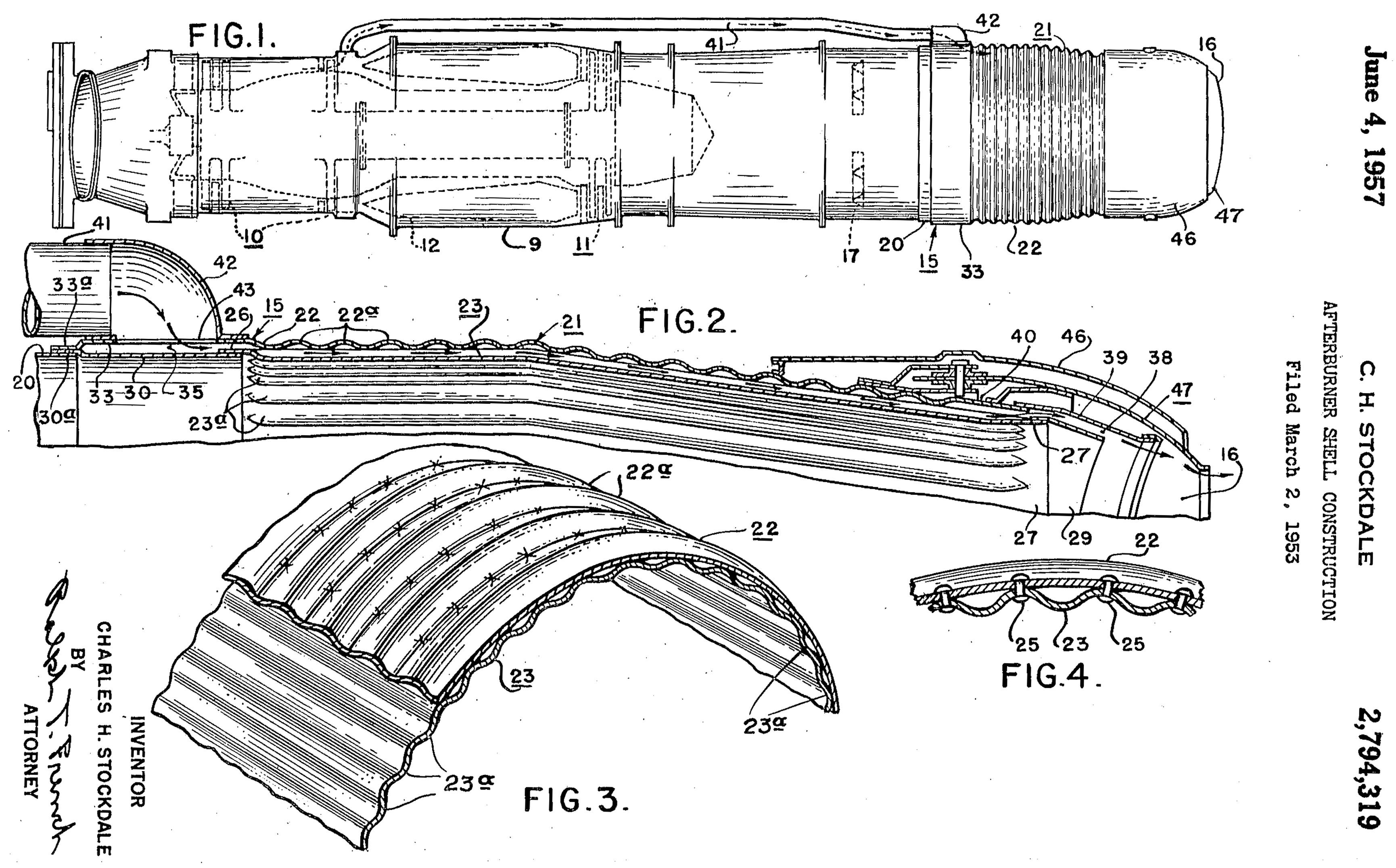
Fig 16. Patent Application For a Double Corrugated AB Shell, drawn 3 October 1949, description written 2 February 1950, applied for 2 March 1953, patent US 2,794,319 was granted 4 June 1957.
2 February 1950: Description for patent drawing for an AB shell with double corrugation created by Charles H Stockdale of WAGT. Patent application held for security reasons.
13 February 1950: BuAer approved the XJ40‑WE‑8 fuel system change to a single connection and the weight increase of approximately 4 pounds to implement it. The airframe contractors were to be surveyed on the proposed connection change and the approval was contingent on their approval. The survey was sent out the same date.
15 February 1950: A report on the progress of the XJ34‑WE‑38 in its 150-Hour Qualification test at the 130 hour point reported that the control system had refused to switch over to the emergency control at 125 hours. Inspection of the control revealed loose components. The control contract had been notified. This control was identical to the -32 control less a few AB related elements.
16 February 1950: Contract 9212 XJ40‑WE‑4/6 Monthly Progress Report for January 1949, Report A-936, BARR Summary. The 50-Hour flight qualification test of the XJ40‑WE‑4 had been completed and the report forwarded to BuAer. The XJ40‑WE‑6 engine was almost assembled and preliminary testing expected to begin the week of 20 February 1950.
24 February 1950: Contracts NOa(s) 9670, 9212 and 10114. BuAer reviewed the contractors’ comments on the survey for the need for an AB operating signal and informed WAGT such a signal would not be required.
Fig. 17. Multi-Petal AB Nozzle Planned for the XJ40‑WE‑10. WAGT P49513, 10 June 1953. (Mislabeled in the WAGT photo card library as a -8 nozzle.) Courtesy Hagley Museum and Library
9 March 1950: WAGT apologized for the delays being experienced by contractors due to the “unsettled nature” of WAGT’s AB development program. Recently a “more rational approach” to the AB cooling problem had been presented to BuAer. (The drawing of the design was not found.) This involved using compressor air for AB cooling. It was expected that a complete proposal of the design which included information on estimated skin temperatures, rate of heat rejection, jet wake pattern which included both temperatures and velocity, along with statements regarding insulation blankets would be completed by 21 March 1950. In the memo, WAGT stated the preliminary installation envelope drawing of the XJ40‑WE‑10 was distributed. The AB would use a similar cooling solution to that proposed for the -8 with the exception of the nozzle. The XJ40‑WE‑10 would use an iris type (multipedal) nozzle instead of the clam shell type on the -8.
17 March 1950: Contract NOa(s) 9670 Review of troubles to-date delaying -32 50-Hour test. Initially, control troubles in the primary, emergency and AB were encountered. These consisted of excessive hunting of the topping governor on the emergency system and excessively rapid accelerations when switching from emergency to primary system and vice versa. Boost pump pressure regulating trouble was encountered. AB low efficiency was due to losses in the ejector and the nozzle. The No. 1 engine was damaged when an oil cooler leak allowed fuel to contaminate oil lines causing bearing and turbine shaft failure. While engine No. 1 was rebuilt, engine No. 2 was diverted from its intended 50-Hour test and used for resolving the control issues encountered by No. 1. As of December, control trouble was still evident. Fuel hunting on the primary and emergency systems topping governor was still prevalent. A fuel leak in the AB fuel regulator required the engine be removed from the test area for repairs. Other issues were linkage interference, ignitor valve leakage, and high engine vibration. The No. 2 bearing failed, damaging the turbine extensively. By 15 January, the controls were satisfactory but a first stage turbine nozzle failed due to a rub with the first stage blades. The failed nozzles fell into the combustion chamber (of the AB). While under repair, a flange spacer was added and the tail actuator was removed because of erratic operation.
In February, a shorter “squeal” baffle was unsuccessful and the mixer sections cracked during testing. An older baffle designed solved the problem. On 28 February the 50-Hour test was started. High vibration after 9 hours forced a halt. The power regulator was erratic and required a tube replacement, the AB air turbine fuel pump failed and the exhaust cone struts failed. The engine was overhauled and resent to test on 10 March. It was removed again because of a hot No. 2 bearing. The seal had wiped the bearing and destroyed it. After replacement of parts, the engine would go on test again on 17 March.
9 March 1950: BuAer notified WAGT that all claims made in their patent application for a AB hydraulic system automatic isolation valve arrangement to prevent the loss of lubricating engine oil were rejected by the Patent Office as unpatentable due to earlier conflicting patents. Such an arrangement would isolate the oil flow being used in the nozzle actuator from the oil flow going to and from the bearings of the engine in order to prevent an engine failure if a leak occurred in the actuating system piping or actuator. The patent application was abandoned.
20 March 1950: Contract NOa(s) 10114, Progress Report for February 1950. Report A-948. BARR Summary. No AB testing had been done since January. Only minor testing to date had been accomplished with the fixed nozzle Phase I AB. Problems (not specified) with the hot streak pattern coupled with only one test cell being available to date had slowed development. The XJ40‑WE‑6 was currently being installed in the cell. Some engine elements were still in design and layout stage and some released for manufacture. Weight reduction elements were being held in abeyance awaiting WAGT’s engineering department release. The BARR felt that having an XJ40‑WE‑8 engine ready for test by July or August 1950 was doubtful.
20 March 1950: Contract NOa(s) 9212, Progress Report for February 1950. Report A-945. BARR Summary. The XJ40‑WE‑6 engine had been assembled and tested. Excessive vibration was found during the first two hours of running. The cause (an out of balance turbine wheel) was corrected and the engine resumed testing 16 March 1950.
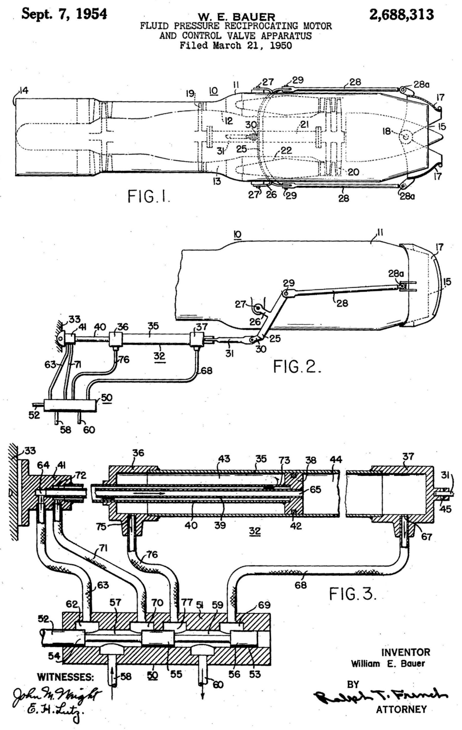
Fig 18. US 2,639,578 Patent Drawing for Eyelid Actuator Positioning Hydraulic Control
21 March 1950: Contract 9670, -32 and -38. Patent Application, Inventor William E. Bauer for Westinghouse. The invention was for a hydraulic actuator and control for opening and closing eyelid nozzle eyelids and holding them in any position between full closed and full open. Patent US 2,688,313 was awarded on 4 September 1954.
22 March 1950: Contract NOa(s) 9670, Progress Report for February 1950. Report A-947. BARR Summary. WAGT attempted the 50-Hour test on the -32 but stopped after 9 hours of operation. Minor “mishaps” plus the failure of the inner cone struts of the diffuser forced a halt. After a full overhaul, the engine was undergoing preliminary tests and adjustment before starting the test again. The qualification test to specification AN-E-32 of the fuel pumping system (dual fuel pump and booster pump) for the XJ34‑WE‑32 and -38 was almost complete. The only element remaining to be qualified was the dual fuel pump splined shaft. Currently over 500 hours of sea level testing were complete. Everything else was fully qualified. The XJ46‑WE‑2 program was making steady progress during the month. The engine elements were being assembled and the first engine would be ready for initial testing by 15 April 1950.
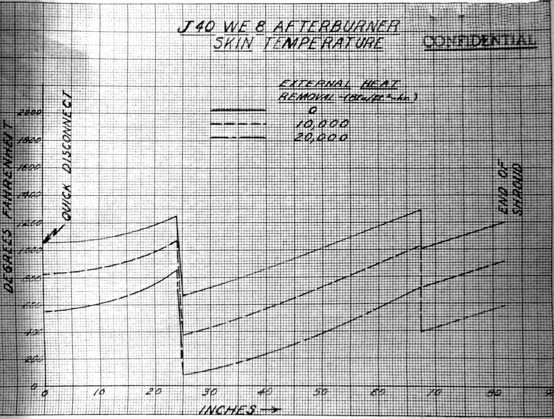
Fig. 19. Proposed J40‑WE‑8 AB Skin Temperature Chart with Compressor Air Bleed Cooling Air Operating
28 March 1950: Contract NOa(s) 10114, WAGT Engine Change 52, XJ40‑WE‑8, survey of revised AB cooling system. The cooling system now proposed would replace the originally designed ejector system with an internal shroud cooled design using compressor bleed air while the AB was operating. Tests had shown the ejector system with an eyelid type nozzle would have been costly in terms of dry performance losses. It appeared to WAGT that the joint engine-airframe responsibility for achieving a satisfactory over-all cooling installation was not the best approach to the engineering problem. Operationally, compressor bleed air would be automatically injected at the initiation of AB operation. At sea level static conditions, the bleed would be 3 lb/sec of compressor air and the heat removal would be 20,000 BTU/ft²/hr. The design would allow the AB to be wrapped with an insulation blanket, the type and thickness being contingent on the limiting aircraft structural temperatures.
30 March 1950: XJ34‑WE‑32 50-Hour Test Flight Substantiation Test, BARR progress report. The engine was resubmitted for the type test on 22 March 1950. At two hours, the AB air turbine pump failed due to shaft bearing failure after it ran about 0.5 hours. The Pesco design had been unsatisfactory in the part. The design would not be qualified and work was underway with Pesco to redesign the pump or design something new that could be considered for service use. Erratic operation (varying temperature and speed) of the power scheduler caused its removal and replacement. The identical part had operated successfully for 150 hours on the -38 type test and for over 300 hours in the laboratory without issue. The removed unit was found to have four screws loose due to improper staking and this had allowed the whole internal mechanism to vibrate, causing damage to the contact points.
At 24 hours into the test, excessive vibration occurred. The stator radial retaining screws in the 6th, 7th and 8th compressor stages were broken off. After screw replacement, the vibration was still present. Further investigation revealed the engine dolly bushings that held the engine trunnion pins did not have the proper 0.060" clearance, preventing the engine from expanding normally when the engine heated up. Creating the proper clearance removed the vibration from the engine. The retaining screw problem was still unresolved.
At 28 hours, the primary control actuator motor armature shorted out. The cause was undetermined. The part had operated successfully on the -38 150‑Hour test. Fuel consumption had steadily increased during the test because the AB seal had become distorted and warped, this allowed hot gases to leak. The actual consumption increase would be determined at test end. In all other respects, the engine performed satisfactorily up to the 28-hour mark at the time of the report.
[End Part 4c of the Early US Navy Afterburner Development Efforts – Westinghouse Electric Company]