Early U.S. Navy Afterburner Development Efforts
Part 4b: Westinghouse – Three Projects Continue Development – J34-WE-32, J40-WE-8, J46-WE-8
by Paul J. Christiansen
Published 9 Oct 2026
Westinghouse Electric Company, Essington, Pennsylvania
The path forward in afterburner (AB) development after the flight testing of the J34-WE-11 model appeared at that time to be quite straightforward. The Westinghouse (WAGT) bid for a significantly more powerful version of the J34 included a separate proposal for an improved version of the current J34 that could return more power to the current fighters faster than the even more powerful version the Navy Bureau of Aeronautics (BuAer) was seeking, the latter requiring more extensive development and a longer schedule. The year and a half faster delivery of the marginally improved model was attractive to BuAer and they contracted for it as well as the more powerful version originally requested.
The quick improvement engine was designated the J34-WE-32 and included an afterburner (AB). WAGT revealed they had assumed they could use the J34-WE-11 AB with a few changes but later revealed not all of these had been identified. The core engine without an AB was designated the J34‑WE‑38. Both engines were to be completely interchangeable to the original engines in airframes already using some model of the J34. The AB was to be designed as a “clip-on” to the core engine so with minor field work a J34-WE-32 could become a J34‑WE‑38 and vice versa. The higher power engine with its longer development cycle was also intended to be as interchangeable as possible with the J34 models and was designated the J46-WE-2. It would have a developed AB from the outset. A non-AB version was designated the J46‑WE-4.
Behind the scenes, BuAer had been pursuing procurement of a much higher power engine in the 7,000 lb thrust range since 1946, but Westinghouse was not part of BuAer’s planning. On their own initiative, WAGT asked to be allowed to submit a proposal. This was allowed and the proposal was accepted for what would become the J40-WE-2. The initial and later models were in parallel development with the other engines. The production model became the J40-WE-6 and a model designation for an AB equipped -6 was not issued initially as BuAer considered the AB a simple attachment to a J40-WE-6. AB development would prove to require such internal changes to the J40‑WE-6 that a new designation J40-WE-8 was applied as this had an AB as an integrated part of the design.
Because of the overlapping development picture for the various AB developments, a (largely) chronological sequence will be followed that will allow the changing requirements and design decisions to appear in order regardless of which engine model was the target. Changes and decisions that applied to more than one engine model are noted. Development of these three AB projects began long before the J34-WE-11 work ended, so we pick up the development threads earlier in the timeline for the three AB projects and accommodate overlap where the -11 work impacted these projects’ development in some way.
* * * Post J34-WE-11 AB Development Projects * * *
28 April 1947: WAGT submitted Proposal for the X40E-2 of 7,500 lb thrust. It was accepted over the competitors as it appeared to have the best overall performance picture when consideration was given to weight, specific fuel consumption (SFC) and basic diameter (40"). WAGT had a quicker delivery schedule as well. This initial engine model did not have an AB design requirement. Its initial design reflected the practices of the 24C8 (J34‑WE-32) then under parallel development. The initial J40-WE-2 model was underpowered and had high fuel and oil consumption. The initial control was from a production J34-WE-22 and it was intended to shift to a future fully electronic control. Early testing changes resulted in the J40-WE-4 model for further development. This also would not have an AB.
11 – 13 February 1948: The Mock Up Board (MUB) for the planned production J40-WE-6 was held. The initial contract model did not have an AB. However, many of the daily discussion items reported included reference to an AB apparently being considered at that time as a simple clip-on attachment. The -6 was to use a dual eyelid nozzle system with a yoke and hydraulic actuator. The control system drew from J34 design but added the complexity required for a variable nozzle. The design assumed the nozzle would be open through most of the speed range, closing down as necessary as the engine approached rated maximum speed. It would be mechanically scheduled and allow rapid acceleration to rated speed. A temperature sensitive override button would permit full maximum thrust to be obtained under all atmospheric conditions. Many solutions to MUB design recommendations were received at later dates but will be covered in the date order they arrived.
8 May 1948: Contract NOa(s) 9670 issued for the J34-WE-32, -38 (X24C8, X24C7) and J46-WE-2 (X24C10) development. The J34-WE-32 was to be based on the J34-WE-30 then under development but with an added AB. WAGT stated later that the assumption was the J34-WE-11 AB could be used with minimal changes, some of those already being known. Both engines were to be able to replace earlier model J34 engines with minimal airframe changes.
| Unapproved XJ34-WE-32 Performance Ratings 22 October 1948 | ||||
|---|---|---|---|---|
| Rating | Thrust (lb) | RPM | SFC (lb/hr/lb) | TOT (°F) |
| Afterburner Operating (Wet) | ||||
| Take-off | 4,900 | 12,500 | 2.60 | 1,380 |
| Military | 4,900 | 12,500 | 2.60 | 1,380 |
| Afterburner Not Operating (Dry) | ||||
| Military | 3,370 | 12,500 | 1.08 | 1,380 |
| Normal | 3,020 | --- | 1.03 | 1,225 |
| Cruise 1 | 2,160 | --- | 0.97 | 890 |
| Cruise 2 | 1,740 | --- | 0.98 | 755 |
| Idle | 205 | 4,000 min | --- | 1,000 |
| Unapproved XJ34-WE-38 Performance Ratings 22 October 1948 | ||||
| Rating | Thrust (lb) | RPM | SFC (lb/hr/lb) | TOT (°F) |
| Take-off | 3,500 | 12,500 | 1.04 | 1,380 |
| Military | 3,500 | 12,500 | 1.04 | 1,380 |
| Normal | 3,150 | --- | 0.990 | 1,225 |
| Cruise 1 | 2,330 | --- | 0.905 | 890 |
| Cruise 2 | 1,925 | --- | 0.89 | 755 |
| Idle | 210 | 4,000 min | --- | 1,000 |
| Unapproved XJ46-WE-2 Performance Ratings | ||||
|---|---|---|---|---|
| Rating | Thrust (lb) | RPM | SFC (lb/hr/lb) | TOT (°F) 21 April 1948 (Approximate) |
| Afterburner Operating (Wet) | ||||
| Take-off | 6,100 | 10,100 | 2.5 | --- |
| Military | 6,100 | 10,100 | 2.5 | --- |
| Afterburner Not Operating (Dry) | ||||
| Military | 4,200 | 0.98 | 1,380 | |
| Cruise 1 | 2,160 | --- | 0.82 | 890 |
The J46 would use the fuel control designed for the -32. The engine would be able to operate reliably up to 60,000 ft and restart up to 45,000 ft. The AB operation and relight limits were not specified.
3 August 1948: In a memo to BuAer, WAGT stated that for the -32 the variable area exhaust nozzle control (fuel, hydraulic, and electrical) was to be very similar to the XJ40-WE-4 control and the work was being coordinated. Completion was anticipated sometime in the Spring of 1949. The AB would use the results of the work on the J34-WE-11 used in the Lockheed XP-90. Many new problems with it had been found but not yet solved. Some redesign after the flight testing was likely to be needed.
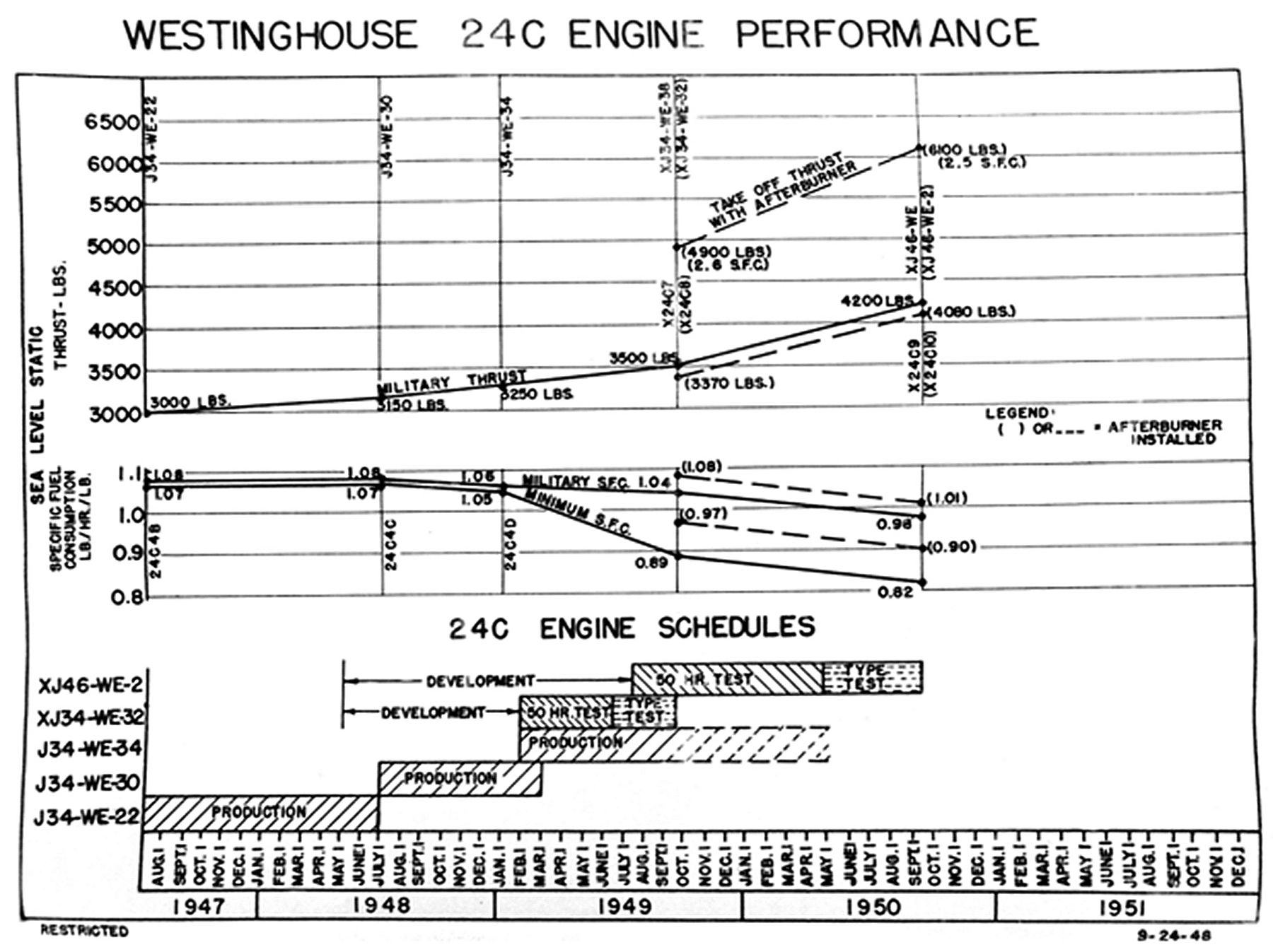
24 September 1948: WAGT sent the engine performance development schedule chart to BuAer. This was meant to show a steady improvement in 24C performance and the 24C10 (J46-WE-2) was included even though it was not actually a 24C development program. (It is possible that the funding environment at that time made it easier to get development money for an existing engine than a new engine development program, hence the continuation of the Model C numbering series by WAGT.)
14 October 1948: Contract NOa(s) 9670, BuAer Memo to Essington Bureau of Aeronautics Resident Representative (BARR) regearding Douglas' proposed use of J46 engines in XF3D-3. Douglas proposed using the J46 in the XF3D-3 if WAGT could agree to provide a version with a bent AB pipe with a 6.5° bend at a point approximately 29" from the AB shroud tail end. BuAer asked that the BARR advise them as to what special engine provisions would be involved to provide the described features in tests, costs, and engine availability. BuAer also recommended that it was most desirable for any AB axial deviation take place at the point where WAGT was planning for the airplane extension pipe to be placed and that the bend be incorporated not in the basic AB but in an extension piece at that point.
|
|
|
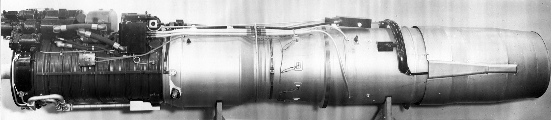
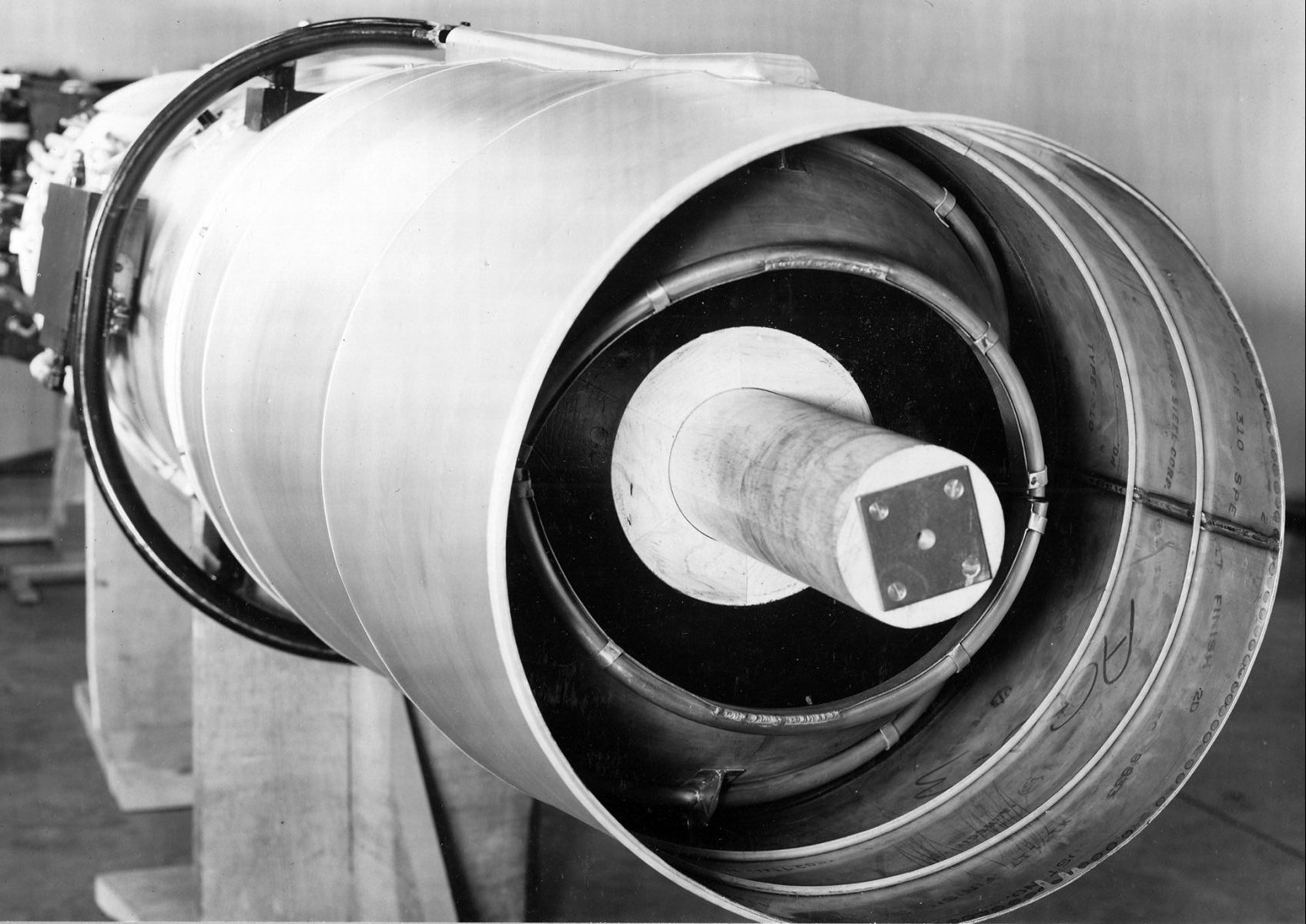
| Fig. 1. WAGT chart showing Model 24C contracted-for performance engines and their improvement delivery schedule. This chart hid the fact that the X24C9 and X24C10 were actually new engines. A later version of this chart used in a J46 program progress report added a “J46-WE-2” label in several places. | Fig. 2. XJ34-WE-32 Mock-Up Left Side View. WAGT P39828, 10/20/1948. Courtesy Hagley Museum and Library | Fig.3. J34-WE-32 Mock-up Exhaust. The variable area nozzle eyelids are visible. WAGT P39827, 10/20/1948. Courtesy Hagley Museum and Library |
25 – 27 October 1948: The Mock Up Board (MUB) for the XJ34-WE-32 and -38 was held in Essington, Pennsylvania. Information presented to the board included:
• Fuel: AN-F-58 (AN-F-48, Grade 100/130 comparable also considered) for both engines.General Installation and Engine Layout.
• Oil: AN-O-9, Grade 1010 for both engines.
• Operating Limits: XJ34-WE-32 – (AB not operating) up to 36,000 ft and up to 40,000 ft with ram pressure ratio above 1.2 with a control range of at least 40% of the power available at a standard day ram pressure up to 1.6. AB would function satisfactorily at all altitudes up to 30,000 feet and up to 35,000 at a ram pressure ratio above 1.2.
• Engine Weight: 1,556 pounds.
The engine and afterburner were partially isolated from one another by means of a flexible expansion joint. The basic engine had three mounts: a universal joint type front mounting lug located on the front bearing support and two main mounting bosses located on the diffuser. The AB was supported by a single mount on the top of the AB, the mount taking side loads only. Any other AB loads were carried through the basic engine mounting system.MUB Recommended Changes: (relative to the AB)
The AB fuel pump was air driven and mounted on the compressor housing bottom aft section. The pump had a capacity of 15,500 lb/hr and supplied fuel to the AB at a pressure of 500 psi maximum. The AB did not require any additional accessory drives.
1. Provide jack points for handling engine and afterburner from the bottom.MUB Major Discussion Points:
2. Provide hoisting provisions for suspending the engine and afterburner.
3. Provide temperature override in the afterburner fuel control.
4. Make the fuel by-pass in the afterburner fuel pump integral with the engine
Number 4 – Desired engine changes were limited by the fact that it was intended to be used in already existing aircraft. “In general, it is desired to point out, that the policy of tailoring the XJ34-WE-32 engine to fit in certain aircraft already designed, has seriously compromised the maintenance serviceability and accessibility of the engine and accessories. Many undesirable features of this engine, although recognized by the mock-up board, were accepted since satisfactory correction would have necessitated interference in certain installations.” Any proposed changes requested as the AB was developed had this design limitation to overcome.MUB Design Changes (relative to the AB):
1. Item 29: Re-location of Afterburner Fuel Pump Inlet Plane – The Inlet Port was relocated to 11" out from the engine centerline and 15.5" below the engine horizontal centerline. The change reduced the engine width at that point by 0.75".
2. Item 42: Redesign of the PT3 Pressure Rake for the Afterburner Regulator Control Pressure – This was redesigned and a new part number assigned. The new part projected 1" less than the original design. The change was to assist in preventing damage to the rake during engine removal.
3. Item 22: Reinforced Quick Disconnect Clamp at Turbine – The design of the quick disconnect clamp between the turbine housing and the afterburner diffuser was reviewed. Field experience had indicated the need for considerable reserve strength in a clamp at this location. The current clamp (not reviewed on the mockup) was reviewed and a new stronger clamp designed. Development testing of the new clamp was planned as soon as some were available.
4. Item 27: Positive Means of Indexing Power Control Lever – Needed to facilitate the rigging of the pilot’s control lever. The power control lever shaft would have a small but rugged pointer keyed to the shaft. The pointer would pass through an arc of approximately 110° during power lever actuation. Above the pointer and visible from below, were scribe lines on the AB fuel control body. External adjustable stops would limit the extreme travel positions of the power lever control. The scribed lines were to designate the static idling speed and the maximum speed positions. Ground adjustments for the minimum static idling speed were to be made by adjusting the setting of the power regulator potentiometer controlling idle speed.
5. Item 7: Afterburner Progress – In a much later response, WAGT issued an afterburner progress report (A-796, 20 January 1949) covering the initial results of their afterburner Model 3 flying in the Lockheed F‑80A for development since it was focusing on its high thrust loss in the non-afterburning mode of 11.5%. Changes had reduced the loss to 7.8%. The hot streak ignition injection point had been moved from in front of the compressor to the compressor outlet. It was hoped the spark coil and spark plug could be removed if the hot streak proved effective. One discovery was that burning efficiency was critical, especially with AN-F-58 fuel, which reached its peak burning efficiency at a lean air-fuel ratio and thus did not allow the burner to reach the high burning temperatures required for high thrust augmentation. Eight more afterburners were being manufactured and two of them had been assigned to J34-WE-32 development testing. The rest were for the Army J34-WE-11 program.
6. Item 30: Afterburner Fuel Control Fuel By-Pass to Dual Fuel Pump Inlet – Fuel pump outlet would be controlled by throttling the discharge. The 1/4" line throttling valve diverted fuel from the pump inlet to the throttling valve in the AB Control. The diverted fuel would be returned to the dual fuel pump inlet through a 1/4" line that would not extend beyond the contour of the mock-up engine envelope.
7. Items 8, 13, 24: AB expansion joint. – Reduce the diameter, add a safety link across the joint and ensure durability in service. The diameter was reduced by 0.5". Two safely links were added across the joint at the horizontal centerline. Stress analysis review showed the joint to be adequate, but testing might reveal changes necessary to ensure good field services operation. The response was accepted and approved by BuAer on March 24, 1949.
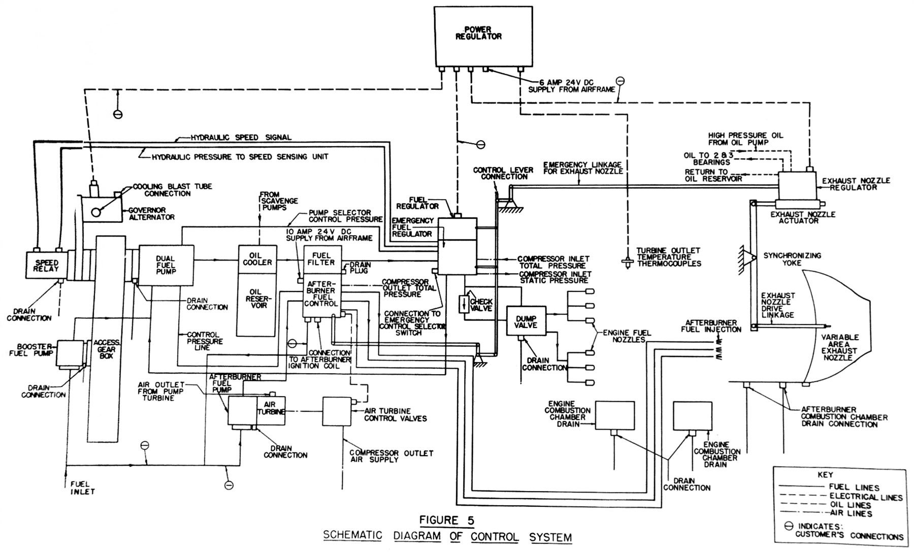 |
| Fig. 4. XJ34-WE-32 and -38 Control System Schematic as of 22 October 1948. Mockup Board Report Attachment. |
5 November 1948: An engine development contract (NOa(s) 10114) for the J40-WE-8 was signed. This covered the development of an AB for the J40-WE-6, the result now being designated the J40-WE-8. Also, the originally contracted for J40-WE-6 and -8 were now seen as necessary “low power” flight test models as part of the contracted J40-WE-10 and J40-WE-12 “high power” development versions. The -10 was to have an AB added to the -12 engine. Until the signing of this contract, apparently no actual development work on the AB for the -8 had been done. The contract required that -6 engines could be reconfigured as -8s or vice versa using a parts “kit”.
1. “In event of failure of the primary power source and/or the hydraulic lines required for actuating the exhaust nozzle, normal operation shall occur automatically with the emergency system.”It was deemed necessary for the system described above to be developed and qualified with the basic engine if the nozzle actuating system reliability was to be consistent with the engine reliability. After the emergency system was successfully developed and qualified, it was desired that it be removed, and the engine supplied with only a primary operating system. After service experience was accumulated, the desirability of adding the emergency system would be reviewed. Installation drawings of the engine should show the emergency actuating system installed with suitable notation of the components. This approach would eliminate the necessity of developing such an emergency system under pressure of acute service troubles that might occur with the primary actuating system.
2. “In event of failure of both primary and emergency power supply systems, the nozzle actuator shall “lock” in the position existing at the time of failure.”
26 January 1949: The -32 and -38 engine weight increases were discussed in a memo to BuAer. WAGT stated: “The weight increases appeared to be so large because BuAer had requested that as much weight margin be removed from the original bid specification as possible when it was submitted. WAGT projected that additional MUB changes still to be processed through would likely add another 25 pounds of weight to each engine”.
| Bid versus Specification Weight Increases (lb) | |||
|---|---|---|---|
| J34-WE-32 | J34-WE-38 | ||
| Dry Weight | Bid Spec | 1,539 | 1,376 |
| Model Spec | 1,698 | 1,448 | |
| Increase | +159 | +72 | |
A detailed breakdown revealed that of the 159 lb increase to date on the -32, 9 lb was due to the AB ignition being re-added after the bid, 9 lb was due to AB regulator changes due to the “3-Pump System”, and 62 lb were the result of AB strengthening.
28 January 1949: Contract NOa(s) 9670 – XJ34-WE-32 Engine Afterburner Expansion Joint. WAGT responded to the MUB change items 13 and 24. The size of the expansion joint diameter was reduced from 2825" to 27.75" and two safety links were added across the joint at the horizontal centerline. A review of the stresses on the safety joint was conducted and the results showed that the current design was adequate. They admitted that as testing progressed, further improvements might be necessary. BuAer approved of the changes and conclusions on 24 March 1949.
8 February 1949: (New Requirement) At a conference on February 8, BuAer expressed interest in obtaining an oil system that could provide an uninterrupted oil flow to the bearings for 30 seconds of inverted flight. WAGT was confident of meeting the requirement but had no details on the time required or the cost. Possible impacts on the AB design were not mentioned.
3 March 1949: WAGT was reminded that they were required to provide all of the components necessary for the Emergency Fuel System design developed and approved under Contract NOa(s) 9051 Report A-600 (not found) on all engines subsequent to that approval. Through discussion, BuAer had become aware that this was not currently planned by WAGT for the J34‑WE-32 or -38. (The Emergency Fuel System discussed here had no provisions for an AB being present on the engine.)
• Automatic – The automatic emergency switch-over system is in effect with system running on the Primary system.
• Check – The system switches to the emergency system and is locked there with an emergency indicating light illuminated.
• Reset – The system can select the Primary system even if it has failed. Normally, selecting Reset would return the system from Emergency to Primary and put it back in Automatic operation.
7 March 1949: WAGT provided a list of known engine changes and oil system areas needing testing before definitive engineering changes needed to provide a 30 second continuous inverted flight capability to the -32 and -38. The investigations would take four months. Cost estimates would have to await the investigation results. Any concerns in the AB area were not mentioned.
Item J. Engine Control System and Operating Requirements14 – 16 March 1949: XJ46-WE-2 Mock-Up Board Information Given to Attendees.1. Covered in WAGT Report A-615 (not found).
2. Essentially the same as that of the XJ34-WE-32. Fuel entered the engine booster pump from the airframe booster pumps. On exit, it went to the main pump and then to the oil cooler and fuel regulators. One outlet from the fuel regulator was a bypass back to the main pump inlet, other outlet routes were to the splitter valve (to the two fuel manifolds) and then to the dual flow fuel nozzles; another was to the emergency fuel pump and emergency fuel regulator to the fuel nozzles with internal changeover for both; the third was from the airframe booster pumps to the AB fuel pump, then to the AB fuel control and then to three outlets to supply the three fuel rings in the AB.
Primary Control – Consisted of a governor alternator regulator, power regulator, power scheduler, fuel regulator, exhaust nozzle actuator, and turbine out thermocouples. The control synchronized the fuel flow and the exhaust nozzle area to the pilot’s power control lever position, providing power at the desired engine rpm and thrust, optimizing the specific fuel consumption and prevented exceeding of the maximum allowable turbine out temperature. On the Primary system, the power regulator received signals from the pilot’s lever, the governor alternator speed and the turbine out thermocouples. The circuits within the control took those inputs to compute the required fuel flow and exhaust nozzle area and transmit signals to the fuel control valve and exhaust nozzle actuator regulator. These adjusted the fuel flow and exhaust area. The detailed description of the internal functions of the control was covered in WAGT report A‑688 section VI (report not found).Valves
Emergency Control – A completely separate manually controlled system, which, without movement of the pilot’s control lever, took over engine control if the governor alternator output voltage failed. With partial or progressive power control failure, the emergency control could be manually selected by the pilot. In emergency, the fuel flow to the engine was accomplished by the emergency fuel regulator while control of the exhaust nozzle area was accomplished by direct mechanical connection from the power lever to the exhaust nozzle actuator regulator. In case the hydraulic supply to the exhaust nozzle actuator failed, the nozzle was locked in the position it was in when the failure occurred.
Dump Valve – This drained the fuel manifolds when the engine was shut down. Approximately one quart of fuel was dumped each time. A tank had to be provided to catch this fuel on the ground or deck. It could be blown overboard in flight or dumped into a safe container on the ground. A flame trap in the tank vent line was recommended.
Fuel Shut-Off Valve – There were three positive, manually operated shut-off valves. The main valve was in the primary fuel regulator and was cam operated from the power lever. It remained closed until the power regulator was moved off a flat spot on the cam opening the valve. The AB valve was toggled so that it remained seated until the power lever was advanced into AB range. The emergency fuel regulator / fuel shut-off valve was manually opened and closed from the power lever. The shut-off valves prevented the flow of fuel if the engine was windmilling.
Fuel Booster Pump – This pump received fuel from the airframe booster pumps and supplied it under pressure to the gear type dual fuel pump.Afterburner Control
Dual Fuel Pump – This pump combined the main and emergency fuel pumps in a single housing. Failure of the main pump selected the emergency pump automatically. The emergency pump was capable of supplying take-off fuel volumes. Selection of the emergency pump by the pilot could be manually accomplished. If the AB fuel pump failed, the main and emergency fuel pumps supplied fuel to the AB at take-off volumes automatically.
Advancing the control lever into the AB range unlocked the AB positive fuel shut-off, energized the AB ignition coil, and successively admitted fuel to the three afterburner fuel rings (providing fully modulated thrust in AB – Author.). Modulation of the AB exhaust nozzle eyelids was automatic. The AB fuel pressure regulator sensed compressor discharge total pressure (air mass) and automatically scheduled the fuel pressure to establish the proper fuel flow. The schedule was based on AB operation at 10,100 engine rpm with the exhaust nozzle area modulated to maintain maximum allowable turbine out temperature.Afterburner Installation Provisions
A quick disconnect clamp was provided between the turbine housing and afterburner diffuser to allow installation of those components separately. The AB diffuser contained an expansion bellows to allow for differential expansion. A single mount was to be provided that allowed for vertical and lateral loads only.Engine Cooling Considerations
A fire seal was provided on the combustion chamber outer casing to the rear of the engine mounts. The fire seal was not designed to support airframe loads and it was recommended that the airframe fire seal designs be coordinated with WAGT. The engine compartment isolated cooling air on both sides of the fire seal. Aft of the fire seal, adequate cooling air was available for the airframe structure and cooling the AB ejector. Forward of the fire seal, the accessories in general, including the fuel and oil lines, were expected to operate satisfactorily up to 150°F. The power regulator, ignition coils and leads had to be held to not more than 165°F. The installation should not restrict AB ejector cooling airflow, as reliability of the AB aft end could be affected. The required cooling flow was 4 lb/sec between the engine and the ejector.Weight
Basic dry engine weight plus unattached components was 1,622 lb. The weight did not include the starter, generator, tachometer generator or hydraulic pump, these being Government Furnished Equipment (GFE). Airframe attached accessory weights (lb) were: Alternator Regulator – 5.0; Power Regulator – 29.0; Engine Ignition Coils and Leads (2) – 13.0, and AB Ignition Coil and Lead – 6.0. The total was 53.0. Afterburner weight was 211 pounds. Total weight was 1,886 pounds.Starting and Ignition
Ignition coils, high tension leads and spark plugs were provided to ignite the fuel in the combustion chamber and afterburner. The AB coil was energized by a switch in the AB fuel control when AB was selected. The three coils were to be mounted in the airframe near the engine with the maximum length of the high tension leads to the spark plugs being the maximum distance from the coils to the spark plugs. Airframe power should be supplied within 9 to 29 VDC.
Electrical Starting System – No provisions were made for electrical starter cables in the front bearing support struts. If electrical starters were used, the cables had to come in through the aircraft inlet duct system, design of which would have to be coordinated with WAGT.
Air Starting System – A pneumatic or solid propellant starter could be located on the starter pad if separate ducts were incorporated into the aircraft inlet duct system. A thickness to cord ratio of between 0.11 and 0.26 was specified for such struts to minimize duct loss. A single strut was not allowable to avoid blade impulses in the compressor.
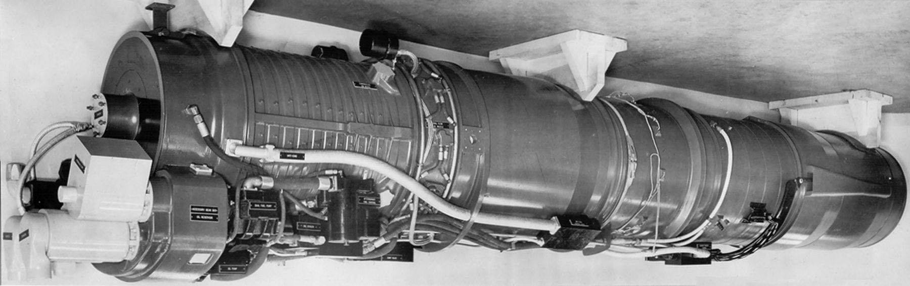 |
| Fig. 5. XJ40-WE-8 Mockup, Left Side, Inverted to Show the Gearbox Arrangement Better, Reviewed by the Mock-Up Board. Note lack of cooling air piping or exhaust nozzle assembly details. Mock-Up Board Report 25 April 1949, WAGT P40793, 4/19/1949. Courtesy Hagley Museum and Library |
14 – 16 March 1949: XJ46-WE-2 Mock-Up Board Report. (Taken from Westinghouse J46 Axial Turbojet Family, Development History and Technical Profiles.)
MUB Discussion:
“The major points of discussion by the mock-up board concerned the control system, the variable area nozzle actuating system, and the lubrication system. Concerning the control system, the presently proposed system includes electronic components which will operate satisfactorily at temperatures up to 165°F only. In addition, the electronic components are so configured as to be unsuitable for engine mounting. The Bureau of Aeronautics’ philosophy on control systems expressed at the subject conference is that control components should be engine mountable if such can be achieved. Location of the control components in the nacelle or engine compartment will be necessary, of course, if considerations of space, size, or environment so dictate. However, it is considered that development should be toward the end of engine mountability [sic] and toward making the control components withstand the same extremes of environment as the basic engine itself. The extreme of locating the control components in the airconditioned portion of the airplane is considered undesirable and to be avoided if at all practicable. To this end, Item 10 ……requesting investigation of the control mounting and environment limitation problem, was approved. This is considered to be a long‑range project and consideration of practical limitations would dictate that the control be at least initially built as then conceived.”
A fuel control system simplification was proposed by WAGT was discussed at the MUB and study was continuing. (This report was initially not issued for the J46 as well, but appeared as “Proposed Simplification of the XJ40-WE-8 Control System”, dated (April 13, 1949. Later in September 1949, the XJ46-WE-2 was added and minor differences were explained for the two systems.) The fuel system related simplification was stated as Item 1. The fuel metering components were simplified by combining the primary fuel regulator and the emergency fuel regulator into a single assembly. The combined assembly would be functionally the same as the present design except for the elimination of the hydraulic acceleration limiter. The change would make it necessary for the pilot to control the acceleration of the engine during emergency operation. A topping governor was included to provide the same speed control as the present system under emergency control as well as extending positive overspeed protection during primary control operation. The proposed system employed a simple throttle valve for emergency fuel control in the range below military rpm and the topping governor to control rpm at Military. Thrust at military rpm would be controlled by the variable area exhaust nozzle. As with the present design the proposed emergency system would take over control either automatically after an alternator voltage failure or as a result of manual selection by the pilot. A table compared the behavior of both approaches when component failures occurred. The proposed change reduced power lever torque, reduced weight and would eliminate over 100 parts.
The emergency exhaust nozzle control was simplified by eliminating all the parts required for mechanical scheduling and replacing them with a single electrical scheduling means. This would receive its power from the aircraft electrical system.
| Failure Mode | Present System Response | Proposed System Response |
|---|---|---|
| Main Fuel Pump | Automatic switch to emergency fuel pump; also manual selection of complete emergency system. | Same as present design. |
| Alternator Voltage Failure | Automatic change to emergency control including emergency pump. | Same as present design. |
| Any Failure of the Primary System | Pilot may select emergency control. Overspeed protection provided. | Pilot may select the new emergency control as described. Overspeed protection provided. |
| Afterburner Control Failure | No provision. Pilot may turn off AB and obtain full Military thrust. | Same as present design. |
| Eliminated or Simplified Component |
Space Reduction |
Power Lever Torque Reduction (% of Current System) | Weight Reduction (lb) | Parts Eliminated |
|---|---|---|---|---|
| Emergency Fuel Control | 80% of Emergency Fuel Regulator | -20% | 10 (8) | 42 |
| Emergency Exhaust Nozzle Regulator | 30% of Exhaust Nozzle Regulator | -40% | 12.5 | 110 |
| Hydraulic Acceleration Limiter | 10% of Primary Fuel Regulator | 0% | 4 (3) | 40 |
| Total | -60% | 26.5 (23.5) | 192 |
1. Fuel Metering System: “Combining the emergency fuel metering equipment with the primary fuel regulator makes it possible to avoid duplication of constant pressure valves, relief valves, and shut down valves as well as presenting a convenient arrangement for providing positive overspeed protection under both control regimes. Elimination of the hydraulic acceleration limiter prevents a duplication of function in the primary control.” “The proposed system for controlling fuel to the combustion chamber will be a single unit housing two fuel valves in parallel and one downstream in series; the latter operated by the overspeed governor. A three-way valve upstream from the two parallel valves will direct fuel to the electrically positioned valve during primary control or emergency control to the other valve, which is positioned by the throttle lever. In both the present and the proposed design a valve will be included to change from the primary to the emergency element of the dual fuel pump simultaneously with a change to emergency control.”
2. Exhaust Nozzle Control: “The proposed emergency exhaust nozzle control will schedule exhaust nozzle area in relation to power lever position as with the present system. Replacing the mechanical control with an electrical one will reduce the number of parts required, decrease weight and save much of the torque required to operate the power lever, but its greatest advantage lies in increasing the reliability and accuracy of the control by elimination of a large number of parts.” “The afterburner could still be used with the proposed system. The exhaust nozzle control is arranged to cause the nozzle to move to its maximum area position when the power control lever is moved into the afterburning range. This does not prevent partial load afterburning operation, but full power will be the most efficient afterburning condition under emergency control.”
The quoted costs (9 September 1949) to make the changes were: XJ40-WE-8 = $102,074.00; XJ46-WE-2 = $98,106.00. There would not be sufficient time to develop the simplified emergency system and include it on the XJ40-WE-4 and -6 or the J34-WE-32 and -38 prior to their 150-Hour type tests. The change could be incorporated on those engines at a later date by means of a change in design. If the change on the XJ40-WE-8 and XJ46-WE-2 was desired, contract amendments were requested to the subject contracts. (As late as 1 June 1950, notes attached to the report state that BuAer’s understanding was that WAGT would include the system on the XJ40-WE-8 and XJ46-WE-2 at no additional contract cost but no formal documentation existed between BuAer and WAGT to confirm that fact.)
1. Remove the ejector shroud and make it an airframe item. WAGT would supply the limits on air flow, skin temp, heat rejection requirement and the effect of weight to the airframe manufacturers. (The airframe manufacturers were to design and produce their own ejector shrouds.)
2. Provide a set of main engine mounting pads near the turbine housing and eliminate the AB flex joint. Not agreed. WAGT would submit data found in research on the flex bellows joint.
3. Make the power regulator, alternator voltage regulator, ignitions coils engine mountable. Raise the ambient temperature limits. Not agreed. WAGT would study.
4. Provide the ability to replace control components without need for factory calibration of new parts. Agreed.
5. Provide a mechanism for locked hydraulic AB actuator lines to avoid rupture from temperature rise. Agreed.
6. Install a short flex hose in the aft section of tubing leading from the oil pump to the eyelid actuator. Agreed.
7. Decrease the power lever torque below 50 in-lb. Agreed.
8. Reduce power lever torque to 25 in-lb. Agreed but the actual number would be coordinated after the Mock-Up Board.
9. Indicate by paint color the portions of the emergency system to be deleted if the simplification proposal was accepted. Agreed.
10. Provide a “cruise” band on the power control for optimum engine cruise regardless of conditions. Not agreed or approved.
11. Revise the AB operating and starting altitudes to 60,000 ft. Not approved. The item was referred to BuAer for review.
12. Engine should be operable at maximum output under all conditions of flight. Not approved.
13. Add the ability for WAGT or the airframe manufacturer to apply an insulation blanket for the AB shell. Agreed. WAGT would study which parts of the AB aft of the compressor flange could be blanketed.
14. Study the proposed simplified emergency fuel system and provide a suitable specification. Agreed that BuAer would study the system and communicate a decision.
15. Clarify the allowable temperatures and heat rejection at that temperature at aft engine components or accessories to which cooling air would need to be supplied.
16. Study the effect of engine driven booster pump failure on the fuel system. Agreed. WAGT to study.
17. Make provisions for emergency eyelid operation and prevent loss of engine oil in event of actuator or line rupture. Agreed. WAGT to provide. The heating value had to be established for the engine specification.
18. Engine ratings should be based on using AN-F-58 fuel with a heating value of 18,400 BTU/lb. Agreed. WAGT would provide.
19. Define engine boost pump and AB minimum inlet pressure with 100°F fuel between sea level and 8,000 ft.
20. Do a design study for interchangeable parts between an AB equipped and non-AB equipped engine. Agreed. WAGT to conduct.
21. Reduce the nozzle control yoke diameter and eliminate the cant in the fairing. Not approved.
22. Reduce the eyelid yoke envelope. Not approved.
23. Move the power control level box as close to the compressor as possible. WAGT agreed to provide information on the extent possible.
24. Provide a stop on the bellows between the engine and the AB to restrict maximum length growth. Agreed.
17 March 1949: Contract NOa(s) 9670 Progress Report A-826 on XJ34-WE-32
The XJ34-WE-32 engine would begin running on or about April 15, with some parts having been borrowed from a J34-WE-34. If early testing went well, the flight substantiation test could start around the end of June, as some accessories would not be on hand until then. This report was not forwarded to BuAer by the BARR until 11 April 1949.
17 March 1949: XJ34-WE-32 Turbo-jet Engine Design Study (A-818) of Turbine Outlet Temperature Override for Afterburner Control
MUB Item 28: Turbine Outlet Temperature Override for AB Fuel Control – WAGT submitted report A-818 after studying the current design, the operational need for, and the impacts of, adding such an override. The board’s reason for the request was to provide protection against overheating the engine or experiencing excessive loss in thrust if the variable area nozzle failed with the nozzle in the closed position with the afterburner on. The study showed that if the normal power control was operating and, with a failed exhaust nozzle, the pilot either attempted to go into afterburner or was already in afterburner and the eyelids were already closed or snap closed on their own, severe compressor stall would occur, causing severe vibration. The pilot could simply move the throttle out of afterburner. Other 24C model engines had operated for extended periods in severe compressor stall without damage although damage to the airframe could occur if the vibration existed for an extended period.
The emergency fuel control presented a different situation. Only a double failure of both an electrical and mechanical nature would have to occur for the engine to be operating in a condition where AB was selected and the eyelids were failed in the closed condition. If the eyelids were closed when the control was moved to the afterburner position, increased fuel would be injected into the AB and the engine rpm would decrease. The fuel flow would continue to increase to the maximum allowed by the acceleration control. The overtemp condition would undoubtedly cause destruction of the turbine within 15 seconds. Since the emergency power control was not automatic and required the pilot to monitor the turbine temperatures both during acceleration and steady state operation near the Military rpm, it was reasonable to assume the pilot would be doing this when selecting or operating in the AB range. The final WAGT conclusion was “Considerable sizes, weight and complexity will be added to the control system by the addition of a turbine outlet temperature override on the afterburner fuel control.” BuAer accepted the recommendation on April 20, 1949.
24 March 1949: In response to the -32 MUB Item 8 request for improved durability of the -32 AB expansion joint, the maximum expansion joint diameter was reduced from 28.25" to 27.75"; two safety links across the joint were added at the horizontal centerline. A stress review found the design to be adequate. Testing continued and changes would be made as results indicated were necessary.
12 April 1949: Contracts NOa(s) 9212, XJ40-WE-2 Engine; Contract NOa(s) 9670, XJ46-WE-2 Engine and XJ34-WE-32 Engine – Revised Design of the Control System for a MUB change from the J40-WE-8 engine regarding simplifying the control system spilled over to the -32 project since they were intended to use essentially the same system. The simplifications would reduce the power lever torque by 60%, reduce the engine weight by 26.5 lb and eliminate 192 parts. As part of the simplification, it was recommended that “the interconnection between the fuel pumps be omitted”. In the original design, this interconnection provided limited afterburner operation in the event of a failure of the afterburner pump. BuAer found the recommended change unacceptable because it would allow a complete loss of the afterburner if either the airplane fuel boost pump or the afterburner fuel pump failed. Since the subject airplanes for which the engines were intended would require afterburning for takeoff, the change was considered unsafe for flight. A conference on the subject was considered in order to review the pumping arrangement and if such a conference was desired by WAGT that they inform the Bureau.
13-14 April 1949: The Mock-Up Board was held for the XJ40-WE-8
Discussion Items:
Engine Description – an improved -6 incorporating an afterburner and its associated controls and components. In addition, it would have a new gearbox with external oil tank between the air inlet ducts and a lubrication system designed to provide continuous engine operation during inverted or negative-g accelerations. The static sea level thrust was 7,400 pounds dry with an SFC of 1.0 and a full afterburning thrust of 10,900 pounds with an SFC of 2.5. The engine was planned to be used in the McDonnell XF3H‑1, Douglas XF4D-1 and the Grumman XF10F-1 (until the -10 models were available) with other applications under consideration by BuAer.
During a prior mock-up review of another AB engine, the responsibility for designing the cooling shrouds of the engine, both primary and secondary, had been deemed the responsibility of the airframe manufacturer. During the -8 review, this was reversed and the primary shroud responsibility shifted back to the manufacturer. The secondary shroud would remain the responsibility of the airframe manufacturer. The logic was that if the airframe manufacturers had to develop both shrouds, they would have to engage in extensive ground testing to develop proper cooling. (It was not noted in the review, but obviously any change in the primary shroud might have had an effect on engine performance beyond the engine manufacturer’s control. The boundaries between the engineering interfaces related to turbojet installations were still in flux.)
The mock-up board generally agreed with the proposed fuel system and concurred with the desire to generally simplify the system. Areas of discussion were lowering the power level torque and fuel pump inlet pressure, but recommendations were deferred for further review by BuAer before final coordination of engine model specification.
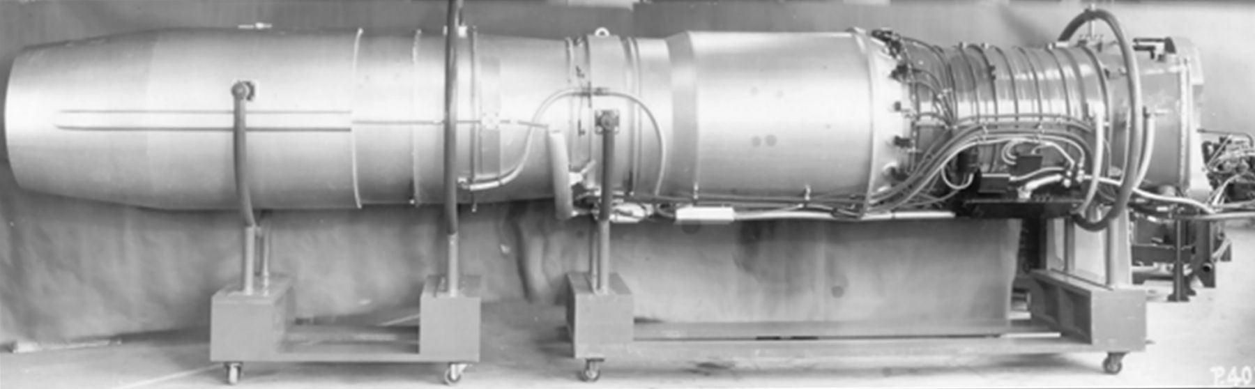 |
| Fig. 6. XJ40-WE-8 Mock-Up Available at the Mock-Up Meeting |
| Rating (Sea Level) | Thrust (lb) | RPM | SFC (lb/hr/lb) | Gas Temp (°F) |
|---|---|---|---|---|
| Take-off (AB) | 10,900 | 7,260 | 2.50 | 1,240 |
| Military (AB) | 10,900 | 7,260 | 2.50 | 1,240 |
| Military | 7,400 | 7,260 | 1.00 | 1,240 |
| Normal | 6,600 | 7,260 | 0.95 | 1,140 |
| Cruise 1 | 5,000 | 7,260 | 0.86 | 840 |
| Cruise 2 | 4,000 | 7,260 | 0.85 | 680 |
| Idle | 450 | 3,000 | 900 | |
| Weight | 3,366 lb | |||
| Max Operating Altitude | 50,000 ft | |||
| Max Air Restart | 40,000 ft / 1.2 ram pressure minimum 95% recovery efficiency | |||
Item 7: – Provide better access to the power regulator blast cooling tube by moving the flange aft to improve clearance. Resolution – Westinghouse redesigned the power regulator housing into a more compact form, which improved the airflow. The power regulator was moved aft to remove it from the adjacent anti-icing hot gas line, changing the clearance from 1.625" to 3.125". They also changed the connection to the Boss type. They intended to make this change on the -6 as well.
Item 10 – Eliminate the present fuel inlet connection on the AB and fuel pumps, which had pads facing downward, and replace them with pads on the front of both pumps. This was approved for the AB pump, to be reviewed after final configuration of the simplified control system was determined. Resolution – The fuel booster pump connection from the airframe was changed to be a single connection supplying fuel to both the engine dual fuel pump and the afterburner fuel pump along with reducing the AB fuel pump inlet pressure requirements to be the same as the engine booster pump. (See also Item 36.)
Item 11 – The engine manufacturer must provide the afterburner ejector (nozzle) that would be in use during the acceptance testing resolution – WAGT forwarded a design to BuAer showing it would be within the existing nozzle dimensions of the -6, the design being subject to minor changes resulting from development and it would add 1 pound to the engine. The design was intended to be used on the ‑6 as well and WAGT asked that approval for the -8 also be the approval for the -6. The initial memo was followed with one of more detail showing the length of the nozzle would increase by 3", increasing engine length to 277±2".
Item 12 – Provide attachment holes for installing a seal flange between the AB shroud and the aircraft structure to prevent reverse flow through the secondary ejector. Resolution – Superseded by AB cooling system redesign.
Item 13 – Provide performance characteristics of afterburner ejector-flow ratio versus pressure ratio for various ejector eyelid positions, needed for overall cooling solution design. Resolution – Westinghouse produced an AB cooling design with all the details in March 1950. The design used compressor air for cooling. The proposal included estimated skin temperatures, rate of heat rejection, jet wake pattern (both temperature and velocity) and information on insulation blankets. This was very similar to the XJ40-WE-10 model design, except that an iris type exhaust nozzle was planned for the -10 instead of the clam shell type on the -8. The design was sent out as Engine Change 70 for review.
Item 16 – Reduce the nozzle yoke size to ease fairing design on the non-AB engine (-6). (Disapproved)
Item 17 – Make provision on the variable area nozzle to permit attachment of a position indicator. (Disapproved)
Item 18 – Relocate AB spark plug to the engine right side provided there is no impact to AB ignition. Resolution – WAGT proposed eliminating the spark plug and its related electrical system completely and switching the AB to hot streak ignition based on successful tests on J34 engines with afterburners. The design change was accepted by BuAer in November.
Item 20 – Minimize the number of engine instruments to simplify the pilot’s duties. (Disapproved – reason given in the mock-up report is that the services would determine the required instrumentation for production aircraft. Given the push for a “simplified” power control system (See Item 28 below) this would require the pilot to be far more involved in engine management, which made it a curious board recommendation.)
Item 23 – Add an (electromagnetic) radiation shield between the AB and the shroud. (Disapproved)
Item 25 – Establish eyelid configuration to determine if aft portion of aircraft is affected. Resolution – Design showed no effect on rear of aircraft after the XJ40-WE-8 engine was lengthened to be interchangeable with the XJ40-WE-10.
Item 27 – Reduce power lever maximum operating torque below 50 inch-pounds, current forces required were too high due to increased friction at low temperatures. Resolution – WAGT suggested that their proposal for the Simplified Power Control System be approved. It provided for a 60% reduction in throttle torque with a maximum of 20 in-lb versus the 50 in-lb of the ‑6 system with the extra AB components presented at the Mock-up Board.
Item 28 – Simplify the control system relative to the pamphlet distributed to the Mock-up Board, “Proposed Simplification of XJ40-WE-8 Power Control System, April 13, 1949”. This would provide for less weight (26.5 lb), fewer parts and the same reliability. Resolution – Simplified system proposed for BuAer review (detailed elsewhere). Originally proposed by WAGT on April 13, 1949 and was in review.
Item 30 – Reduce the time for obtainment of full military and AB thrust from a 50% military power setting to less than the current 1.5 to 2.0 seconds from 50% to full military and then 3.0 to 5.0 additional seconds to full AB (7.0 seconds total). Required for carrier wave-off condition. Sent to BuAer for specification coordination.
Item 31 – Make the quick disconnects in the fuel lines between engine and afterburner be self-sealing, or if possible, bring the fuel lines into afterburner forward of quick disconnect flange. This required a study. Resolution - Final design submitted with new fuel system lines shown.
Item 32 – Locate quick disconnect fittings for all three AB fuel lines below the horizontal centerline to consolidate access to a single area. This required a study. Resolution - Final design submitted with new fuel system lines shown.
Item 36 – Reduce the boost pump inlet pressure requirements to reduce excessive weight in boost pumping equipment along with the excessive power drain on the engine. Referred to BuAer. Resolution – The AB fuel pump was changed to accept fuel from the single feed of the airframe booster pump at the same pressure as the dual engine pump. This was surveyed with Engine Change 49.
Item 37 – Provide more positive means than V-type quick disconnect clamp for AB attachment to engine and allow for small amount of initial misalignment between engine and AB. (First part disapproved and the second required a study.) Resolution – WAGT sent in a proposal in September 1949 to respond to part two, but later asked BuAer to ignore the proposal, which was superseded by a later proposal. The later proposal was reviewed and approved, adding two pounds to the engine weight.
Item 48 – Remove tachometer alternator gearbox (the mounting pad rpm was so close to the desired speed, the gearbox was deemed unnecessary in the circumstances). Resolution – Was described and approved.
26 April 1949: Attachment Point of Exhaust Nozzle Actuator (for XJ34-WE-32). MUB Item 18: Change the Attachment Point of the Exhaust Nozzle Actuator – BuAer had received two communications on the new location and they had shown the new location at different positions. BuAer asked WAGT for a clarification of the definitive new location being proposed.
3 May 1949: The Specification for the WAGT-24C8-2D (XJ34-WE-32) was forwarded to BuAer. It was dated 5 April 1949. The specification for the -32 and-38 was Appendix A.
6 May 1949: (date approximate) The first -32 engine runs were made using only fixed tails and partial accessories. The initial thrust was 3,500 lb at 12,500 rpm. Cast vanes replaced the initial rolled ones and with opened up the inlet guide vanes the thrust increased to 3,610 lb at 12,500 rpm with a turbine inlet temperature of 1,525°F. Mechanically the engine had been satisfactory over 21 hours of operation.
10 May 1949: Accessory Cooling Requirements. WAGT published a chart on the operating limits of the -32. It showed the electrical temperature limits on the engine did not adversely affect the engine operation below 815 kt at 11,000 ft and permitted higher speeds up to 35,500 ft. Above that altitude, the maximum aircraft speed was limited to approximately 990 kts unless refrigeration was used.
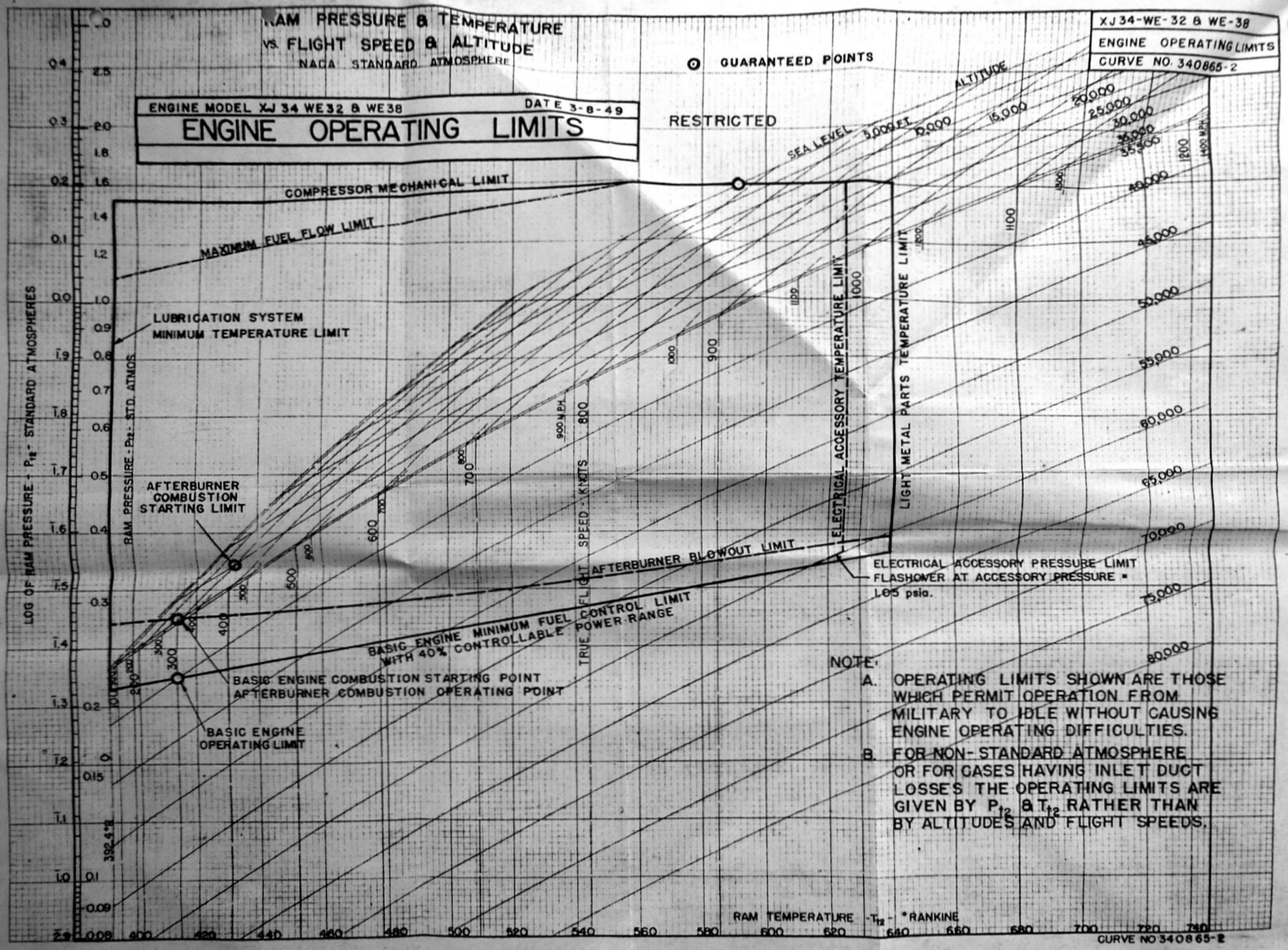 |
| Fig. 7. XJ34-WE-32 Engine Operating Limits |
For improved cooling, WAGT enlarged the power regulator container slightly and produced a new outline drawing.
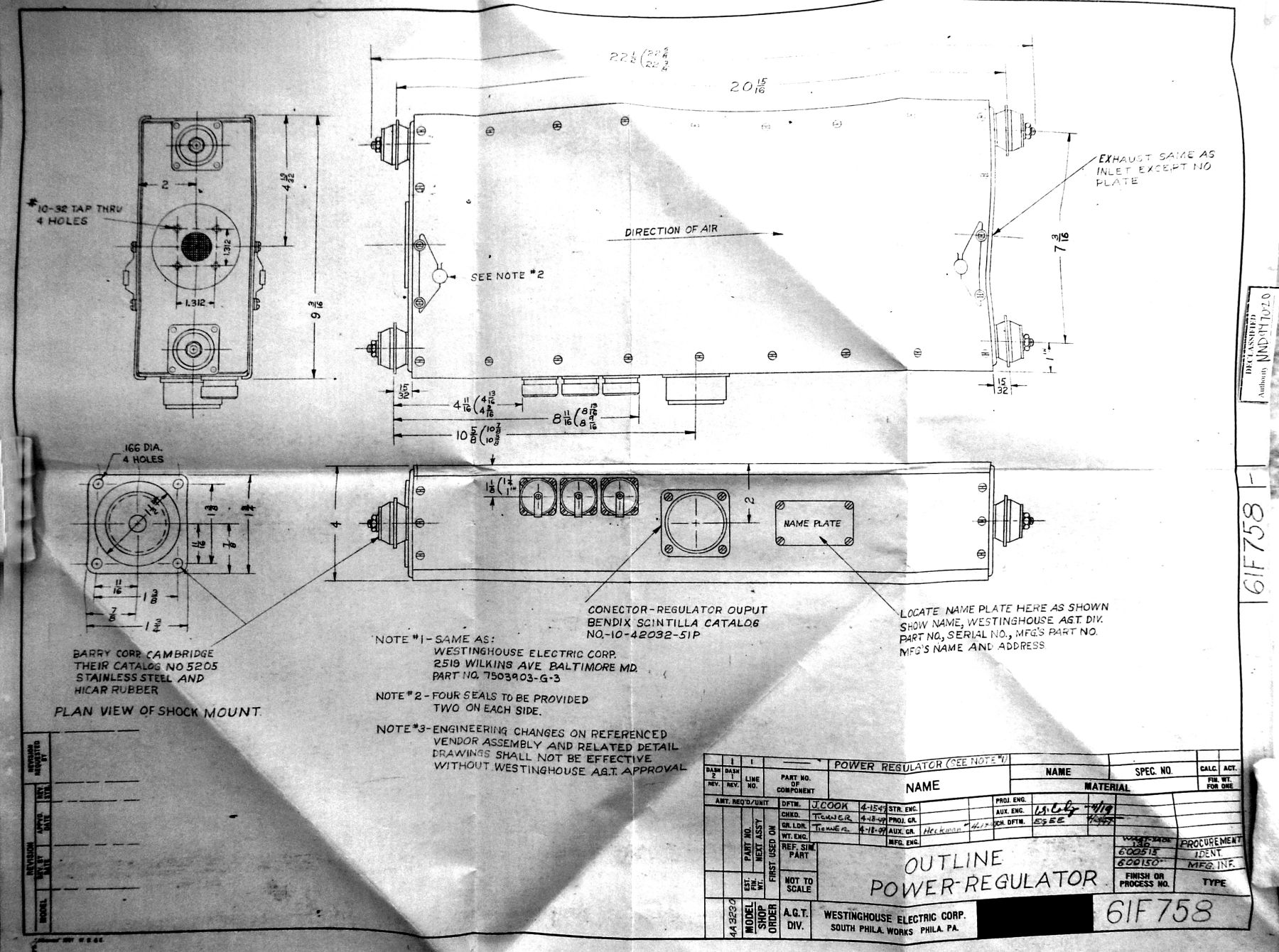 |
| Fig. 8. Revised -32 Power Regulator Outline Chart Part 61F758 |
23 May 1949: BuAer approved the specification covering the -32/-38 engines with an exception was taken to the power control as it radiated interference higher than the current control and ordered continued development to reduce the radiation to a level compatible with a service aircraft. The current level was accepted temporarily.
June 1949: At some point in this month, BuAer began referring to the AB equipped version of the XJ40-WE-6 as the XJ40-WE-8. Prior to that, correspondence related to an AB in the J40 program can be found in the Contract NOa(s) 9212 (XJ40-WE-2, -4, -6) files and the Contract NOa(s) 9670 (XJ46-WE-2; XJ34-WE-32, -4) files.
6 June 1949: Contracts NOa(s) 9670, NOa(s) 9212, NOa(s) 10067, and NOa(s) 10114 Engine Data Distribution. WAGT had sent out informal -32 engine data to several airframe manufacturers and BuAer took strong exception to WAGT proceeding in this way. BuAer had to support engine guarantees to the airframe manufacturers and if the informal data differed from that formally approved, it would place BuAer in a difficult position. WAGT recommended distribution plans be approved for all engine information and be put in place. A rigorous control was recommended and WAGT sent in an example of such a control along with samples of the control sheets for BuAer to comment on and/or approve.
8 June 1949: Contracts NOa(s) 9670 and 10114 XJ46-WE-2 and XJ40-WE-8 Turbo-jet Engines, Fuel Pump Inlet Requirements, Establishment of: Afterburner pump inlet pressure requirements for the XJ46-WE-2 and possible solutions were reviewed by BuAer in June. They noted that the requirement was that the main and emergency fuel pumps had to sustain maximum afterburner fuel flow at 1.1 ram and 100°F fuel temperature even if the aircraft booster pump failed. If the AB fuel pump inlet pressure requirement was too high and the airframe boost pump failed, the AB fuel pump would cavitate and stop pumping fuel, resulting in AB failure. During a take-off this could be disastrous. BuAer asked that the AB fuel pump inlet pressure be lowered to avoid an AB failure possibility and also to reduce the airframe pump flow requirement, thus assisting in easing the airframe fuel supply solution.
BuAer – “What is the effect on the engine control if one of the teeter valve coils should fail? Would the main control valve be closed and cause the engine to shut down?”
WAGT Response – “Failure of either coil in the teeter valve would cause a momentary motion in the direction controlled by the “unfailed” coil. As soon as there is any motion from the desired set point, the feed-back circuit operates to de-energize the “unfailed” coil causing the main control to stop in some mid-position. Further study has revealed that if a light spring is placed so as to urge the main control valve in(to) the open position any failure of the teeter valve coil controlling the opening of this valve will result in no change in fuel flow or pressure. The only effect will be to reduce the available power for moving the main control valve. Any failure of the other teeter valve coil will cause the main control valve to open wide and control of the engine will be maintained by the emergency overspeed valve. It is believed that the addition of the opening spring to the main control valve will satisfactorily prevent closing of the main control valve upon electrical failure of either teeter valve coil.”
BuAer – “Is it possible to start the engine in the air using only the emergency power control system?”
WAGT Response – “The design of the power control system is such that air starts can be made using only the emergency power system.”
BuAer – “Would it be desirable to provide a pressure pickup downstream of the main control valve to sense pressure failure and change over to the emergency system?”
WAGT Response – “Study had revealed that the emergency pump was automatically selected upon failure of the primary pump as indicated by a pressure failure. There were no valves downstream of the pumps that could stick or malfunction to lower pressure below that needed for minimum throttle flow setting. Inclusion of a pressure pickup would serve no purpose.”
BuAer – “Why not use the three-position switch for the preflight check system to standardize the cockpit equipment in all aircraft using emergency systems? During the conference, reference (a), the discussion indicated that a reset mechanism would be required and that, when the emergency system is selected either manually or automatically, it should be locked in to prevent cycling between the primary and emergency systems in case the primary system should recover. (Such as the case of a bad electrical connection to the solenoid valve which continues to make and break the circuit).”
WAGT Response – “Further study of this problem revealed that the three-position switch is more desirable than the original proposed three pole single throw switch. Accordingly, this Contractor will redesign the system to include provisions for using the pre-flight system as described in reference (d). The addition of these provisions to the simplified power control system will increase the weight of the system and consequently the engine by approximately 3 pounds and will increase the volume by approximately 27 in³ or a package 3"x3"x3". This preflight check system will be applied to engines in accordance with the earlier references.”
14 June 1949: Contracts NOa(s) 9212 and NOa(s) 9670, Turbo-Jet Engine Research and Development Programs. This requested a weight breakdown for the current major development models. The AB related data were:
| AB Weight (lb) | ||
|---|---|---|
| J34-WE-32 | J40-WE-10 | J34-WE-2 |
| 270.0 | 568.0 | 287.0 |
(Note that WAGT is not even including the J40-WE-8 in the list as it was no longer considered a program leading to a production engine, but a development tool only to get to the J40-WE-10.)
16 June 1949: Contract NOa(s) 9670, Westinghouse Specification WAGT -24C8-2B Covering the Model J34-WE-32 and -38 Engines – Electrical Component Temperature Limits for: In spite of WAGT’s submission of report A-836 (not found) on the temperature limits of the electrical components of the J34-WE-32/-38 and J46 and which stated that testing was underway to determine if the limits could safely be raised, BuAer continued to push for an expanded electrical component operating temperature envelope. They noted that the last specification for the XJ40‑WE-6 stated the electrical component limits were 165°F in continuous operation and 200°F for a five-minute operating period for the engine. Since the electrical components on the J34-WE-32 and -38 were essentially the same as the XJ40-WE-6, they asked that the specification on the J34-WE‑32/-38 be modified by adding the 200°F five-minute operating period limit as well.
16 June 1949: WAGT memo to BARR on the XJ40-WE-8 Engine Furnished Afterburner Cooling Ejector. Reversing an earlier decision, BuAer had requested the engine manufacturer supply the cooling ejectors, not the airframe manufacturer. This was now made the engine manufacturer’s responsibility again. WAGT was confirming that since the cooling ejector had been in the pricing for the engine, no additional cost was involved in supplying them. The supplied ejector would remain within the installation envelope of the aircraft manufacturer supplied ejector as shown previously as much as possible. The actual design was in progress. It was being based on the testing of the previous J34 ejectors. Any design changes after the initial design for the J40-WE-8 would be surveyed with all aircraft manufacturers concerned.
22 June 1948: Contract NOa(s) 9212 – Monthly Progress Report (May 1949) for XJ40-WE-x, (BARR cover letter). Summary of testing on the -2 and -4 stated the electronic control “had proved a little troublesome”, but the trouble was “minor” and WAGT was “continuously working to clear this up.” (This system would also be used on the XJ40-WE-8 modified for an AB).
24 June 1949: Contract NOa(s) 9670 Progress Report (for May 1949), A-854. (Note, BARR cover memo calls the -32 engine a “XJ46-WE-32”). The basic engine was still being tested without its AB. Total running time to the end of May was 39.13 hours. AB running was planned to begin in June. (The last para states that the XJ46-WE-2 program purchasing had begun.)
27 June 1949: Contract NOa(s) 9212, Westinghouse XJ40-WE-6 and XJ40-WE-8 Engines, Afterburner Support and Fuel System Provisions for: The Mock-Up board on the XJ40-WE-6 (1 April 1948) had recommended the -8 AB be designed as a cantilever extension of the -6 engine. WAGT had felt it would require too much weight in the -6 to provide the strength and recommended a study. The study, A-789, 12 September 1948, recommended the cantilever approach not be used. The excessive increase in engine weight required and the additional development time necessary to design an engine which would operate successfully while under the influence of AB vibration transmitted to it though the AB extension. The engine weight increase would be a minimum of from 16 to 108 lb depending on the length of the AB extension used. Complete details of the items needing strengthening and the flight loads on an AB considered were included. WAGT stated that the AB should be supported separately in the airframe and should use a flexible joint for expansion and mis-alignment and to isolate the AB from vibration from the engine.
AB vibration was gone into in detail. “Experience in the design of afterburners has shown that they produce abnormally high vibrations in operation which if not controlled to an allowable magnitude may prove destructive to the afterburner. It is felt that even after much development afterburners will produce vibrations of some magnitude, and the possible effect on the engine of vibrations transmitted to it from the afterburner when the two units are rigidly connected is not known. It is possible that these vibrations may necessitate the redesign of various engine components, which would result in a considerable increase in engine weight. In order to express the feeling on the subject of afterburner vibration, it might be well to cite the case of the Westinghouse J-34 Jet Engine, which is to run with a separately supported afterburner, and a very short extension containing a flexible joint. The engine is guaranteed for ½ hour of operation with the afterburner on, while this same engine without an afterburner is expected to operate successfully through a 150-Hour type test. It is of importance to note that the engine, with the afterburner mounted in the manner described above, will experience (more) vibration than that which should be considered in this study, since both the afterburner supports and the flexible joint between it and the engine will tend to dampen out and isolate afterburner vibrations.”
 |
| Fig. 9. AB Used for Calculations in Report A-749. The assumed AB was a single walled type weighing 2 lb/in of length when the sheet metal used had a 0.049" thickness. The extension diameters ranged from 32" to 36" were the diameters of the engine and the AB. The AB was 60" in length and weight was 400 lb. The eyelid type nozzle was an upgraded version of the standard engine nozzle due to the increased temperatures. Its diameter was 36", its length 20" and its weight 120 lb. This report was finally approved by BuAer on 27 June 1949 since BuAer by then had realized that the -6 would not use an AB in any known planned installation and the -8 was being designed under another contract NOa(s) 10114. |
29 June 1949: Contract NOa(s) 9670: WEC Turbo-Jet Engine XJ46-WE-2; Make Attachment Provisions for Control Rod Brackets on Regulators; Survey: This asked airframe manufacturers to mark up four different drawings of possible places to place the brackets and the necessary stud length(s) that would be needed for each.
8 July 1949: Contract NOa(s) 9670 – Westinghouse Specification WAGT-X24C10-20, dated 9 May 1949, Covering Model XJ46-WE-2: The specification was found to be unsatisfactory and “requires almost complete revision. The specification reflects almost none of the requirements and features mutually agreed upon for the specifications covering the models J34-WE-32 and XJ40-WE-6 engines, although these engines are all of a very similar type." The area of weight increase required particular attention. The redraft had to be done according to the new Specification AN-E-31a and conform to Specifications AN-E-30a, -32a and -33a. (These were currently being prepared for printing.) Copies of the proposed specifications were to be provided by BuAer for guidance until the printed copies became available. Little in the way of exceptions to the new specifications was expected, but a complete shift to the new specification was to be accomplished.
AN-E-32a stated that the engine power control and electrical ignition system qualification tests were to be specified in the Model Specification. A draft of the qualification test was provided for the hydro-mechanical elements of the power control. The qualification test requirements for the electrical elements of the power control and the ignition system were to be forwarded at an early date.
Specific to the AB, the AB fuel pump test time was to be included for all operating conditions, since the AB pump operated at any time the engine was operating. The pump need only be discharging at the maximum pressure one-fourth of the time of the main pumps for each condition. All other operating time should be at the conditions at which the pump would operate without the AB in operation. BuAer instructed that a new paragraph be inserted stating that the engine should function satisfactorily for at least 10 seconds during inverted flight although the fuel flow to the engine might be interrupted during the maneuver. Satisfactory functioning would be considered to be achieved when the engine returned to normal operation within the operating limits shown on the specification without further action of the pilot when the negative acceleration was removed.
Another new paragraph was to be included stating “Provisions are incorporated to prevent loss of engine oil in the event of breakage or leakage of the exhaust nozzle actuator control lines.”
a. “Sea level, -10°C operation with fuel pressure at the inlet of the engine driven fuel booster pump down to 24 in. Hg. absolute and with line losses up to the customer’s fuel inlet connection on the engine as high as 6 in. Hg.BuAer noted that for the majority of changes requested where no explanation was given, these changes were to conform with previous agreements with WAGT on variable area nozzle engines.
b. “At 5,000 ft altitude -10°C operation with fuel pressure at the inlet of the engine driven fuel booster pump down to 20 in Hg. absolute and with line losses up to the customer’s fuel inlet connection on the engine as high as 4 in. Hg.”
8 July 1949: Monthly Progress Report for June 1949, Contract NOa(s) 9670
This showed the -32 AB had been operated wet for 1.2 hours and 8.6 hours dry during the month. Total thrust at Military was 4,600 lb versus the 4,900 lb guaranteed. Thrust augmentation was not satisfactory and tuning of the burner to utilize the gas pressure and velocity distribution in the engine was being initiated. Revised AB flame holders for greater durability were being tested. For improved Chance Vought airframe clearance (model not specified), a new design of flexible joint was being devised. It would have a smaller outside diameter than previously. All AB fuel control drawings had been released for manufacture. A bread-board type of hot-streak ignition valve was built and tested and layout drawings had been completed. The AB fuel pump had bearing and seal modifications that were in process to improve durability of the Pesco pump. A meeting had been held with Thompson Products to review the status of their air-turbine fuel pump for the -32. A sample unit was due to WAGT by the end of July. The electronic control cable and junction box was being delayed to incorporate BuAer changes of adding a pressure switch and electric control relay, both adding to the weight. Power control electromagnetic leakage was being reduced using filters at all customer connections and at the connection of the thermocouple harness. Other parts were modified to reduce emissions.
For the XJ46-WE-2, various engine component parts were in various stages of production.
[End Part 4b of the Early US Navy Afterburner Development Efforts – Westinghouse Electric Company]
Send mail to
 with questions or comments about this web site.