
Westinghouse J46-WE-8A and J46-WE-8B
Part 3: J46 Fuel System
Compiled by Kimble D. McCutcheon
Published 26 Dec 2016; Revised 28 Dec 2016
Contents
Part 1: J46 Overview
Part 2: J46 Lubrication System
Part 3: J46 Fuel System
Part 4: J46 Electrical System
 |
Overview
The J46-WE-8A engine was designed to function on JP-4 (MIL-F-5624A) fuel and used approximately 11 gpm without afterburner and approximately 2.5 times as much when augmented. In the event of airframe fuel boost pump failure, the engine-driven fuel boost pump could supply sufficient fuel for limited basic engine and afterburner operation. Fuel pressure was measured at the engine-driven fuel boost pump inlet and indicated airframe boost pump pressure only.
Engine Fuel Flow
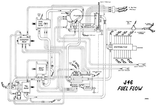
Fuel at airframe boost pump pressure (4-30 psi) was delivered to the engine-driven boost pump inlet where pressure was monitored for cockpit indication. A throttling-type pressure regulating valve at the single-stage centrifugal engine-driven boost pump outlet automatically regulated discharge pressure to 10-30 psig for inlet to the dual fuel pump. Fuel flow was normally not assisted by the boost pump except when an airframe boost pump failed or during rapid changes in fuel flow. The boost pump outlet was a drain and point of lowest constant pressure for the entire fuel system. Flow through the dual fuel pump to the common outlet was either through the primary or emergency spur gear element. Normally it was through the primary element except in the event of a primary pump failure or during the emergency pump check, which was accomplished from the cockpit with engine operating. All fuel from the dual fuel pump was routed through the fuel filter cast as part of the afterburner fuel regulator. This fuel was for the engine regulator ONLY. The filter element was a replaceable #10 micron paper cartridge.
Fuel flow arriving at the fuel regulator was adjusted to meet engine demands and the remaining fuel was bypassed back to the dual fuel pump inlet, which was physically at the boost pump outlet. Metered fuel then flowed to the dump valve and on to the distributor valve where the flow was divided into 36 equal parts for feeding the 36 vaporizing tubes.
The dump valve was a spring-diaphragm operated valve that was closed during engine start by fuel pressure and opened by a spring to drain the distributor system into the dump tank on engine shutdown.
Fuel supply for the two torch igniters was tapped off just up stream of the dump valve and a solenoid valve was placed in this line to limit the flow to the 30-second ignite period.
If while operating in afterburner the airframe-mounted boost pump failed to maintain sufficient pressure at the afterburner pump inlet, the engine-driven boost pump would also supply fuel to the afterburner pump via a crossover line and through the double check valve.
The overspeed relay, acting similarly to a propeller governor, received high pressure fuel from the fuel filter, which was transmitted to the fuel regulator overspeed valve to keep it open. Open reaching maximum engine rpm this pressure was bled back through the overspeed relay to the boost pump outlet, causing the overspeed valve to begin closing. In order to obtain isochronous control of the engine, a balance or compensating line was used between the overspeed relay and overspeed valve.
Two lines from the engine-driven fuel boost pump were routed to a cooling chamber in the afterburner pump to cool the impeller bearing while not operating in afterburner. Hydraulically operated bypass valves in the engine-driven boost pump were positioned to select the pumping element by two bleed lines running from the dual fuel pump to the fuel regulator pump selector solenoid. An electrical connection for the emergency pump warning light switch was provided. Fuel from the fuel regulator acceleration and overepeed drain valves was returned to the boost pump outlet.
Powered by phpBB © 2001, 2005 phpBB Group |