Packard Builds the Rolls-Royce Merlin
Part 5: 1 Jul to 31 Aug 1942
Compiled by Kimble D. McCutcheon
Published 1 Oct 2026; Revised 2 Oct 2026
2 Jul 1942. On 25 Jun 1942, Fredric Flader, the Curtiss-Wright Airplane Division-Buffalo Plant Chief Engineer complained to the MatCmd commanding general for the fourth time about spark plug fouling and ignition harness failures on P-40F and P-40L airplanes equipped with Packard V-1650-1 engines under contracts W-535-ac-15802, W-535-ac-18685 and W-535-ac-22714. Flader's previous letters had been sent on 19 Feb, 6 Mar and 20 Apr 1942. Flader suggested that an experimental test be conducted using an ignition harness of increased wire size and increased insulation thickness in order to remedy these conditions. [Letter, Curtiss-Wright to MatCmd. 200.] In his 2 July reply, Jesse Vincent, Packard's Vice President of Engineering, reporting that while Packard agreed that the stated undesirable conditions existed, Packard was not permitted under the terms of the R-R agreement to make any changes that would affect interchangeability of either spark plugs or ignition harnesses produced in England. Vincent had discussed this with James Ellor of R-R, who had agreed to a harness design change provided Packard could do so without affecting spark plug interchangeability. Packard was having a sample harness made up that would incorporate as many U.S.-type detail parts as possible, which would be shipped to Curtiss-Wright for flight testing. [Letter, Packard to MatCmd. 206.] On 7 Jul 1942, Production Engineering Section Chief Col C.R. Cook requested a sample harness similar to the one Packard proposed to send to Curtiss-Wright be forwarded to Accelerated Service Test at Patterson Field for Army flight testing. He also requested that Curtiss-Wright flight test data be forwarded so it could be coordinated with Experimental Engineering. [Letter, Col Cook to Col Carroll. 223.]
2 Jul 1942. Production Division Chief Brig Gen K.B. Wolfe wrote the Eastern Procurement Division District Supervisor complaining that the Cuno Engineering Corporation, Meridian, Connecticut oil filter, which MatCmd had directed to supply oil filters to Packard for the V-1650-1 engine, had only delivered 30 filters. He requested an investigation and that every effort be expended to have Cuno expedite its delivery schedule. [Letter, Gen Wolfe to EPD District Supervisor. 207.]
4 Jul 1942. While visiting Packard an Air Service Command Supply Branch representative learned that the V-1650-1 control mechanism was being furnished as a complete assembly to field units. Packard claimed this was necessary because of the way Stewart-Warner Corporation, the control mechanism vendor, was manufacturing the unit. Control units for about 5,700 engines had been delivered this way. Packard thought the original Stewart-Warner drawings covering these parts would permit complete interchangeability of all component parts and would render it practical to maintain these control units in the field. Col C.B. Stone, III, Chief, Supply Branch, recommended that a Production Division representative be assigned to Packard in the capacity of Project Engineer and be charged with the duties of reviewing then-current production policies, not only those that expedited production, but also those that alleviated servicing problems in the field. [Memorandum, Col. Stone to Chief, Production Division. 208.]
4 Jul 1942. Col George E. Price, Acting Chief, Pursuit Branch, Production Engineering Section, wrote the Aero Equipment Branch Chief complaining of trouble with vibration in P-40F and P-40L airplane engine installations. This had caused carburetor air scoop cracks, throttle rod and engine control rod breakage, header tanks cracking and radiator leaks. Curtiss-Wright had conducted tests using Fabreeka pads (tightly-bound cotton duck layers impregnated and reinforced with synthetic rubber) for engine mounting, which had resulted in smoother operation and less trouble keeping engine mount bolts tight. Packard was taking action to supply these pads as a temporary expedient until a more satisfactory mount, such as a Lord mount, could be provided. [IOM to Aero Equipment Branch Chief, Wright Field. 209.]
4 Jul 1942. The British Air Commission (BAC) was asking Curtiss-Wright's permission for Rolls-Royce (R-R) in London to review manufacturing particulars of the Wright roller-clutch two-speed supercharger for its review. Col B.W. Chidlaw, AAF Assistant Chief of Staff was seeking the Experimental Engineering Section Chief's comments and recommendations as to approving the release of such information. [IOM, Chidlaw to Experimental Engineering Chief. 210.]
6 Jul 1942. Col Carroll notified Packard that V-1650-3 calibration was expected to be completed on 8 July and that MatCmd would be ready to confer with Vincent on 9 July. [Telegram EXP-7613, Col Carroll to Packard. 213.]
7 Jul 1942. The Wright Field Chief of Staff had received a telegram from Special Army Observer in London, England, which listed Packard Merlin 28 defects.
A. Bad fretting on the front connecting rod arch resulting in fatigue and breaking at the bolt hole.
B. Incorrect supercharger clutch settings giving insufficient free travel.
Measures taken to correct these defects were:
1. Engines would be stripped and all rods examined for fretting until this no longer appeared. R-R was correcting this defect by hand-reaming the connecting rod bolt holes in a special jig and turning the rod around.
2. The R-R Glasgow Shadow Factory had developed a machine facilitating the setting of clutches under operating conditions and had designed a new setting lever.
Packard was aware of this trouble and was correcting it in a similar manner. Other minor defects included:
A. Leaks at cylinder head stud tubes and transfer ferrules glycol sealing rubbers due to the wrong material being used.
B. Failure of both cam bevel race cages on a type test engine due to rubbing on its diameter wearing the bore.
C. Upper vertical drive lock plate was soft.
D. Incorrect crankcase blending at the reduction gear housing base and at the engine feet.
E. Cracked webs on the coolant pump top half webs.
The Chief of Staff asked whether such defects had been reported on V-1650-1 engines, and if so, what corrective action was being taken. He also asked what corrective action was being taken on engines already en route. [Telegram E-71, Wright Field Chief of Staff to Technical Executive. 215 – 216.] Col Carroll replied that same day that V-1650-1 connecting rods had exhibited bad fretting on the forked connecting rod arch, resulting in fatigue and ultimate failure. No action had been taken to correct this condition on either the engines en route or in service. This condition had been corrected on production engines by tightening the forked rod bolts so that a 0.006" – 0.013" uniform stretch was obtained. Action on service engines was pending.
One supercharger clutch had failed in service but it was not known if it failed due to an incorrect setting. No action was planned until the failure cause had been determined. Stud tube and transfer ferrule coolant leaks had appeared in several service engines. This was corrected by changing the material from neoprene to natural rubber and it was planned to replace all seals at the first overhaul. No corrective action was taken for engines then en route. There had been no cam bevel race cage failures, and no upper vertical drive lock plate failures. However, a change in design had been made to overcome the weakness and would be implemented at the first overhaul. Crankcase cracks had occurred on several engines due to incorrect blending during acceptance test, but none had been reported in service. This was probably because the cracks were extremely difficult to locate. Production engines had been corrected by changing the casting pattern to eliminate sharp corners. No coolant pump web cracks had been reported. [Telegram EXP-T-7623. Col Carroll to Technical Executive. 217 – 220.]
8 Jul 1942. In a letter to the Power Plant Laboratory (PPL) Vincent stated that he had learned MatCmd was considering having Packard manufacture the V-1650-3 two-stage two-speed supercharger for installation on existing V-1650-1 engines. In order to continue manufacturing Merlin 28 engines for the British Government and at the same time produce up to 200 V-1650-3 superchargers per month, it would be necessary to equip an entirely new production line to manufacture the new supercharger. This would include special wheel case and all two-speed drive parts as well as the two-stage supercharger proper. While considering the complications of this program with the large number of new machines required in mind, Vincent decided the program would be greatly simplified by using the same two-speed drive for both single- and two-stage superchargers. This led to Packard layout drawing #679, "V-1650-3 Two-Speed Supercharger Drive and Bearings Adapted to V-1650-1." He enclosed three blueprints. The two-speed drive could be used by only changing the number of teeth in the supercharger rotor shaft drive pinion and the mating drive gears. The supercharger front bearing assembly could also be used without change. In addition to simplifying production, this arrangement would provide for automatic gear shifting and elimination of the oil that entered the supercharger from the front and rear bearings. Vincent suggested rebuilding a V-1650-1 to include a V-1650-3 drive, which could be constructed in a short time and put through a standard type test.
Vincent thought the British Government would react favorably to this construction once it had been proved, because it would simplify manufacturing, provide for automatic gear shifting, and eliminate excess oil going through the supercharger. It would also simplify engine installation. Vincent planned to discuss this with MatCmd on 9 July. [Letter, Vincent to PPL. 225 – 226.]
10 Jul 1942. London had sent a complete set of strengthened Merlin 61 connecting rods for delivery to Packard. The Ferry Command in Washington was unable to locate these and requested that Col Carroll, the Experimental Engineering Section Chief, attempt to locate them. [Telegram EX-688, to Col Carroll. 233.] On 11 July, Col Carroll reported that Packard had not received the rods. [Telegram EXP-T-7638, from Col Carroll. 235.] In a telegram sent later that day, Col Carroll reported the connecting rods had been received by his office and would be forwarded to Packard. [Telegram EX-701. from Col Carroll. 236.]
10 Jul 1942. Packard engineer John H. Grimes had prepared a report extolling the virtues of American aluminum alloys over British ones. According to Grimes, the American alloys had superior physical properties and British alloys contained certain critical materials not contained in American alloys. Maj A.F. Wentzel, Chief, Technical Control Branch, Inspection Section, requested that Grimes prepare a table to be attached to his report that would compare the two alloys. [Letter, Maj Wentzel to Packard Army Air Forces Regional Representative (AAFRR). 234.]
10 Jul 1942. 1st Lt L.E. Kinkade authored two memorandum reports about V-1650-1 engines that had failed in service, resulting in Unsatisfactory Report Nos. 42-103, dated 11 Jun 1942 and 42-105, dated 15 Jun 1942. Both Morris Field engines had failed, resulting in a forced landing for both aircraft. In both cases, the engines were removed and sent to the Wright Field PPL for evaluation, where no engine abnormalities were found. The investigators concluded that the pilots had let their engines get too cool while descending, which resulted in rough operation. The cold engine operation was not satisfactory at either low or high rpm. The investigators recommended that pilots be advised to watch coolant temperatures during a long glide and if the temperatures got below the normal operating range the pilots close the radiator flaps in order to keep the coolant temperatures in a nominal range. [10 Jul 1942 Memorandum Report U-EXP-M-57-8333. Failure of V-1650-1 Engine, A.F. No. 41-46817. P171594, and 10 Jul 1942 Memorandum Report U-EXP-M-57-8332. Failure of V-1650-1 Engine, A.F. No. 41-46633. P171596]
13 Jul 1942. Four V-1650-1 engines had been received at the Fairfield Air Depot, torn down and inspected in the engine overhaul shops. None had the latest cylinder-liner-to-block coolant seals. Approximately the first 150 engines had the first-design PN 600255 seal. Packard Alteration Order No. 1133 dated 11 Feb 1942, changed the seal design and the seal to PN 600147. Investigators concluded that these coolant leaks were due to the early seal design, which was inferior to the latest design. Since no such failure had been reported in engines incorporating the latest seal design, investigators recommended incorporating the latest seal design. [13 Jul 1942 Memorandum Report U-EXP-M-57-8337. Failure of Liner to Block Coolant Seals, Part No. 600255 on V-1650-1 Engines, A.F. Nos. 41-46597 and 41-46556. P171588.]
13 Jul 1942. Col Cook wrote Packard requesting that all future correspondence listing Packard-Merlin serial numbers use the Army Air Forces serial number, which was preceded by AF, as well as the Packard serial number, preceded by the letter A. [Letter, Col Cook to Packard. 239.]
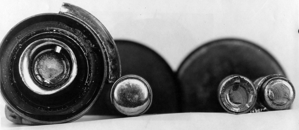
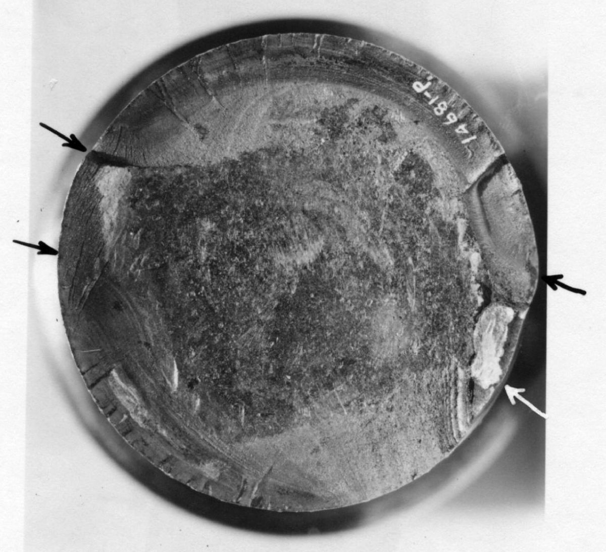
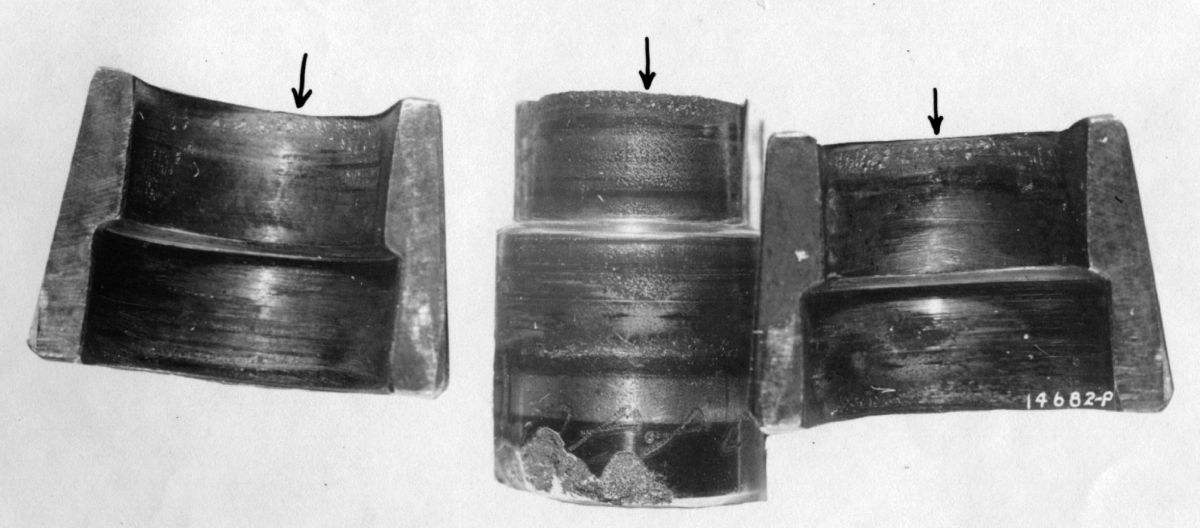
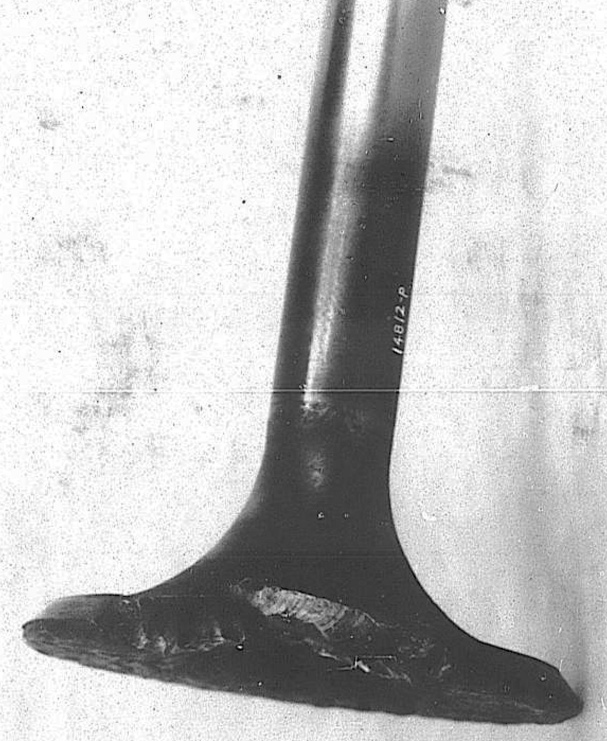
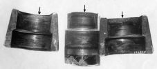
14 Jul 1942. On 23 Jun 1942, the Materials Laboratory had received intake valves from the PPL. The valves, drawing No. 600440 (obsolete as 13 Jan 1942), were galled in the wedge lock area, which resulted in fatigue failure. PM05Figs. 1 – 3 illustrate the galled condition and progressive valve failure. Aeronautical Materials Specification 5700 was the intake valve material, which was equivalent to stainless steel type #343, plus a 0.020 to 0.050% molybdenum content. The wedge material specified by drawing No. 600434 was AMS 6310, which was equivalent to SAE X4340 steel (minus the chromium content), with a 28 – 33 Rockwell "C" hardness. The actual hardness tests on the 12 submitted valves, including the two failed valves, ranged from 13 – 26 Rockwell "C". The valve wedge hardness ranged from 28 – 30 Rockwell "C".
Recent changes had been made to the intake valve and valve wedge. The new drawing No. 600447 incorporated a change to the valve stem lower end, with a minimum hardness of 12 Rockwell "C". The valve wedge was redesigned from a new material, AMS 4625 phosphor bronze, as specified in drawing No. 600441.
Conclusions: The two intake valves and the valve wedge submitted to the Materials Laboratory were of an earlier design as shown on drawing Nos. 600440 and 600434. Examination of the failed intake valves (PM05Fig. 1, PM05Fig. 2, PM05Fig. 3) at low magnification disclosed a series of small but well defined fatigue patterns in the fractured surface outer circumference. Further examination of the immediate external surface revealed a narrow band (about 0.031") of galling (PM05Fig. 3) at either the lower or upper fillet in the recessed section nearest the valve stem end. The valve wedge was also galled in the mating area. It was noted, however, that the small area on the valve stem between the wedge half sections was free of gall marks. Careful inspection of multiple fatigue patterns revealed that the gall marks acted as the nuclei while the small area between two adjacent wedge sections were nuclei-free. This observation suggested that the valve-wedge galled condition caused intake valve failures. Two other intake valves taken from the same engine only showed a slight grace of galling and in one instance the same as previously discussed. However, it could not be determined whether an improper fit between the valve and valve wedge or whether some other mechanical condition induced galling and subsequent failure.
Specimens cut from the failed area disclosed a satisfactory microstructure of uniform carbide distribution. Of note, one valve that did not fail exhibited finer carbides with an undesirable core area banding. This was a further indication that these valve failures exhibited [14 Jul 1942 Memorandum Report U-EXP-M-8270-1M. Intake Valves from a Packard Rolls-Royce V-1650-1 Engine. 241, P171492.]
 |
 |
 |
| PM05Fig. 1. |
PM05Fig. 2. |
PM05Fig. 3. |
14 Jul 1942. The BAC complained that the British Ministry of Aircraft Production had examined 200 spare Packard valves and 5 valve sets from Packard Merlin engines. These valves were electrolytically etched and chalk tested, which revealed the following defects:
(a) Local patching of "Brightray alloy" was extensively in evidence, which was contrary to the British Rolls-Royce practice. Brightray is a typically 80% nickel 20% chromium alloy, resistant to high-temperature erosion and used for hard-facing exhaust valves; it was originally developed by Henry Wiggin and Co., Birmingham, England. Valves that passed the etching and chalk test only were being fitted by MAP to engine while spare valves showed this patching were being held pending type test completion, which, it was hoped, would prove the effects of this condition. Apparently 20% of valves exhibited this patching.
(b) Seven Packard engine exhaust valves showed seat cracks, which were considered serious owing to the possibility of fatigue failure. The cracks may have been the result of shrinkage during welding.
(c) Six valves had been rejected for blow holes beyond the standard permitted by the Rolls-Royce Salvage Scheme No. 50. This information had already been passed to Packard via Rolls-Royce via its Packard plant representation.
(d) All inlet valves from recertification engines were regularly being electrolytically etched and chalk tested. The chalk test was made as soon as possible after the valve head regrind by immersing a valve head in acetone with finely divided chalk in suspension. The suspension would be drawn into any cracks by capillary action. When the valve was removed from the suspension, its exterior would rapidly dry, but the liquid in the crack would leach out more slowly, making a visible wet line around the crack.
(e) Apparently both Thompson Products and Wilcox Rich inlet valves were equally affected except that Thompson Products valves were free from seating cracks. No faults were reported on Wilcox Rich exhaust valves but 30% of Thompson Products exhaust valves inspected had the patched "Brightray.
These details had been passed to the BAC Inspector, who was to ensure that the AAFRR at Packard was informed of all details, according to the agreement to keep Wright Field informed of all major difficulties. [Letter, BAC to Wright Field Inspection Section. 246 – 247.]
Jul 16 – 18 1942. Lt L.E. Kinkade visited Packard to determine the status of the P-40F service test airplane assigned to Packard, which was at Detroit City Airport awaiting installation of a new engine with all the latest modifications. This engine was to be painted white to make any oil leaks more visible. Lt Kincade conferred with Vincent and Ellor about blocking the boost control to determine whether it was the cause of throttle lag reported in P-40F airplanes. After determining that the spark timing was approximately the same under takeoff conditions with the boost control blocked off as when it was operating, Packard was to investigate the throttle lag cause. Ellor directed Packard Chief Test Engineer R.N. DuBois to keep the reinforced connecting rods that had been delivered to Packard by the Ferry Command as spares. The remainder of Lt. Kinkade's time was spent inspecting engine assembly on the production line and adjustment of engine controls during acceptance test. He also spent time with the service school instructor to review valve timing, magneto timing and general service instructions. [24 Jul 1942 Memorandum Report EXP-M-57-503-680. Conference on V-1650-1 Engine and Inspection of Packard Plant. P192621, 272 – 273.]
17 Jul 1942. Lt L.E. Kinkade commented on a 30 May 1942 Bolling Field Unsatisfactory Report No. 42-72 documenting a supercharger failure on V-1650-1 AF No. 41-46592. Inspection of the subject engine revealed that the engine's sudden stoppage was caused by the PN 600655 supercharger impeller drive shaft ball bearing failure. This was caused by impeller drive shaft misalignment, probably the result of the supercharger housing replacement. The ball bearing had failed first, letting the impeller drive shaft drop out of position, causing the impeller to strike the supercharger housing and damage the impeller, tail shaft bearing, supercharger housing and impeller and diffuser. Many broken diffuser and impeller parts were found in the large induction pipe between the banks. The bearing balls dropped to the wheel case bottom and got into the oil system. The backfire screens prevented any large broken parts from entering the cylinders. Only the small chips that could pass through the backfire screens were found in the combustion chambers. A few such failures occurred on the first Packard-built engine and were caused by misalignment of the impeller drive shaft. The subject engine's supercharger section was so badly damaged that it was impossible to make alignment or clearance checks, but apparently the ball bearing failed due to misalignment, which was the only such failure reported to date. Lt Kinkade recommended no further action except to record the report for posterity. [17 Jul 1942 Memorandum Report U-EXP-M-57-8351, Failure of Supercharger Impeller Drive Gear Shaft Ball Bearing, Part No. 600655, V-1650-1 Engine, A.F. No. 41-46592. P171855.]
18 Jul 1942. Maj A.F. Wentzel, the Inspection Section Technical Control Branch Chief, wrote the AAF Procurement Central Procurement District Supervisor about Merlin 28 supercharger clutch setup. In its 6 Jul 1942 letter EH/T/71015, the BAC relayed information taken from an R-R report on supercharger unit checks of three Packard Merlin engines.
(a) Adjustments and Clearances
| | Standard | Engine A-190 | Engine A-191 | Engine A-122 |
|---|
| (i) Toggle Over | MS 0.042" – 0.055" | 0.080" | 0.047" | 0.050" |
| | FS 0.050" – 0.065" | Right 0.052" | 0.073" | 0.046" |
| | | Left 0.051" | 0.053" | 0.045" |
| (ii) End Floats | Minimum = 0.030" | MS 0.052" | 0.054" | 0.049" |
| | | Right 0.044" | 0.033" | 0.035" |
| | | Left 0.042" | 0.041" | 0.043" |
| (iii) Free Travel | MS 0.145" – 0.180" | 0.075" | 0.071" | 0.042" |
| | FS 0.115" – 0.120" | Right 0.115" | 0.122" | 0.108" |
| | | Left 0.113" | 0.104" | 0.116" |
| (iv) Free Period | MS 0.040" – 0.055" | 0.325" | 0.300" | 0.225" |
| | FS 0.030" – 0.065" | | | |
| (v) Toggle Heights | MS 0.075" – 0.090" | 0.101" – 0.106" | 0.099" – 0.115" | 0.102" – 0.111" |
| BOLD values were out-of-specification. |
| FS = Fast Supercharger Speed |
| MS = Medium Supercharger Speed |
Clearly, Packard was having trouble properly adjusting the clutch mechanism.
(b) Definitions
(i) Toggle Over. This is the amount by which the roller drops down behind the cam, measured from the position with the rollers on the cam to the full "toggle over" position; when the relay piston was at its stroke end.
(ii) End Floats. These were checked with the clutches in position on the casings and were measured as the clutch pack full travel – relative to the housing – from the fully disengaged position – the "toggle over" – to the fully engaged position.
(iii) Free Travel. The clearance between the thrust race actuating piece and clutch weight actuating fingers in the fully engaged position.
(iv) Free Period. The distance between the disengagement of one clutch and the engagement of the other, measured in inches of cam lift at the camshaft.
(v) Toggle Heights. The respective clutch weight finger heights above the fulcrum pin tops, the two figures being minimum and maximum.
(c) Comments on the Settings
Service clutch failures had primarily been due to the lack of clearance between MS actuating piece and the MS clutch weight fingers. Under running conditions, several factors come into play that are not taken into account in a static check, such as the free travel check above, and which all combine to considerably reduce this clearance, before any elastic clutch plate comparison takes place, all of which combine to reduce this clearance. Centrifugal force on the clutch weights causes a considerable reduction in this clearance before any elastic clutch plate compression takes place, due to the settling of linings on the plates and the expulsion of air and oil from between the plates. The carrier plate deflection under load and temperature, the elastic plate compression due to centrifugal force all build up to reduce this clearance further; in many cases the fingers were running against the actuating piece when the clutch was driving and reducing the axial clutch pressure, resulting in persistent clutch slipping. An important factor was that the consequent clutch lining wear in service further aggravated the position by reducing the clearance between the actuating piece and clutch weight fingers. R-R experience was that the figure obtained for MS free travel (0.075") was dangerously low. In initial builds R-R worked to a minimum of 0.145" while the minimum clutch endurance test was 0.130".
The MS toggle-over was greater than the FS toggle-over. R-R practice favored the FS clutch with the higher setting since the neutral position was found more rapidly in an MS to FS gear change. The effect of a high toggle over on the FS cams was to retain the clutch in MS gear until an oil pressure sufficient to drive the piston straight through its stroke without any dead spot.
(d) In order to further determine the MS clutch characteristics, springs of higher loading than the standard 1 lb were fitted and toggle heights taken:
Merlin 28 A-190
| Toggle No. | Toggle Heights (inches) |
|---|
| Spring Force | 1.0 lb | 6.5 lb | 10 lb | 22 lb |
Equivalent Direct
Compression Load | 16.5lb | 107 lb | 165 lb | 353 lb |
| 1. | 0.106 | 0.34 | 0.145 | 0.170 |
| 2. | 0.104 | 0.123 | 0.130 | 0.160 |
| 3. | 0.101 | 0.128 | 0.131 | 0.156 |
| 4. | 0.102 | 0.142 | 0.134 | 0.157 |
| 5. | 0.106 | 0.138 | 0.132 | 0.155 |
| 6. | 0.105 | 0.134 | 0.146 | 0.160 |
| Average | 0.104 | 0.135 | 0.136 | 0.160 |
Difference from
Standard 1 lb spring | 0.031 | 0.032 | 0.056 |
Merlin 28 A-191
| Toggle No. | Toggle Heights (inches) |
|---|
| Spring Force | 1.0 lb | 6.5 lb | 10 lb | 22 lb |
| 1. | 0.110 | 0.115 | 0.118 | 0.121 |
| 2. | 0.099 | 0.112 | 0.116 | 0.120 |
| 3. | 0.107 | 0.117 | 0.121 | 0.123 |
| 4. | 0.115 | 0.123 | 0.126 | 0.130 |
| 5. | 0.113 | 0.124 | 0.127 | 0.131 |
| 6. | 0.113 | 0.123 | 0.124 | 0.128 |
| Average | 0.110 | 0.119 | 0.122 | 0.126 |
Difference from
standard 1 lb spring | | 0.009 | 0.012 | 0.016 |
Merlin 28 A-122
| Toggle No. | Toggle Heights (inches) |
|---|
| Spring Force | 1.0 lb | 6.5 lb | 10 lb | 22 lb |
| 1. | 0.105 | 0.116 | 0.121 | 0.127 |
| 2. | 0.106 | 0.117 | 0.122 | 0.127 |
| 3. | 0.102 | 0.113 | 0.118 | 0.123 |
| 4. | 0.110 | 0.119 | 0.122 | 0.129 |
| 5. | 0.111 | 0.124 | 0.127 | 0.131 |
| 6. | 0.103 | 0.121 | 0.127 | 0.132 |
| Average | 0.106 | 0.117 | 0.122 | 0.127 |
Difference from
standard 1 lb spring | | 0.011 | 0.016 | 0.021 |
On engine A-190, the rivets were not tightly binding the clutch linings to the driven plates, as evidenced by oil squeezing out from under the linings when direct hand pressure was applied. (Driven plates on the other clutches were more satisfactory.) The fit between the driven plate splines and clutch housing was tight and tended to drag in operation. The steel plates were parallel and the lining attachment to the steel was good. The MS actuating lever was set to the old Derby value of 0.049" for the drop from center line and roller center. The present value was 0.068"; this enabled the requisite clearance between the actuating piece and the clutch weight fingers to be more readily obtained.
The engine A-122 mechanism, when changed from FS to MS gear, when the MS actuating piece was being withdrawn from the clutch weight fingers the MS lever jammed in some position not fully withdrawn from the disengaged position, which explained the low MS free travel. This jamming prevented the roller from following the cam profile when it should have been on the cam base circle (fully engaged position). The gap between the roller and base circle was to have been 0.103", which would have been a direct increase of 0.052" to the MS free travel had the jamming not occurred. The jamming was caused by the forked tongue on the actuating lever web, PN 605875, to be fouling the actuating plate outside diameter against the whitemetalled sleeve upon which it rode. Heavy wear was noted both on the forked tongue ends and the corresponding actuating piece outside diameter points upon which it rode. The white metal was also noted at the actuating piece jam points. A lever dimensional check showed the 1.750" dimension from the control shaft bore center line to the forked tongue end to be reduced by 0.075". Full advantage of the roller eccentric had not been taken during the clutch setting since 0.030" was still available for adjustment between the set position and the maximum available. Due to the very small free travel, heavy double lines were apparent on the MS clutch weight fingers, showing that under running conditions in MS gear the clearance between the actuating piece and clutch weight fingers was taken up. The clutch linings showed slippage signs although no overheating was apparent. The Merlin 20-series supercharger clutch mechanisms were known to be highly loaded, which made it important to ensure all adjustments were nominal in order to prevent serious damage. [Maj A.F. Wentzel to Packard. 253 – 258.]
20 Jul 1942. Packard sent revised copies of its Specification A.M. 1025b, dated 20 Jul 1942, to the BAC and to Wright Field. This specification covered 14,000 additional Packard-Built Rolls Royce Merlin 28 engines. In addition to changes making the specification agree with the contract wording, the new specification included the following:
- Radio Shielding Ignition, PN 611007, was replaced with a new PN 610088, which improved high altitude performance.
- The PN 610067 Fuel Priming Pipes Assembly was replaced with a new PN 610087, which was necessary due to other improvements.
- ¶ E-17c had been rewritten to cover radio shielding modifications to improve high-altitude operations. This included Packard's final magneto recommendation.
- ¶ E-19 included carburetor details that had been approved for production.
- ¶ E-24 was rewritten to provide two exhaust flange gaskets for each exhaust port and to eliminate the exhaust flanges as standard equipment.
- ¶ E-26a was rewritten to specify acceptable starting motors when installed in British aircraft.
- ¶ E-26d was rewritten to describe the fuel pump drive adapter and fuel pump connections.
All changes had been reviewed and approved by Ellor. [Letters, Vincent to BAC and MatCmd. 261 – 264.] On 28 Jul 1942, the British Air Commission officially approved A.M. 1025b dated 30 Jun 1942 and used this as a basis for ordering 14,000 Merlin 31 and Merlin 61 engines under requisitions RFDA 8967 and 9902. [Letter, BAC to MatCmd Production Engineering Section. 278]
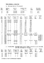
20 Jul 1942. Col Carroll sent Packard a proposed V-1650-3 model test schedule based on a normal rating at 2,750 rpm and 46.5 inHgA. When establishing the V-1650-1 ratings, the British all-out level flight and maximum cruise were used for the military rating and the normal rating respectively. The AAF normal rating differed from both, being defined as the maximum rating for continuous power whereas the British international rating was limited to 30 minutes; the normal rating differed from the British maximum cruise rating in that it was used mostly for climbing conditions instead of maximum cruising conditions. The Merlin 61 had such a wide spread between these British ratings that it was desirable to establish a normal rating approximately half-way between a British international rating and the British maximum cruise rating.
| Run | Accum
Time
(hrs) | Period
Time
(hrs) | Running
Type | Man
Pres
(inHgA) | rpm | SC Gear | Throttle
Position | Cooler
Out Temp
(°F) | Desired
Temp Rise
(°F) |
|---|
| Altitude Dynamometer Running |
| 1 | 5 | 5 | Cont | 46.5 | 2,750 | Low | Full | 194 | 146 |
| 2 | 10 | 5 | Cont | 46.5 | 2,750 | High | Full | 194 | 238 |
| 3 | 15 | 5 | Cont | (1) | 2,650 | High | Full | 194 | 222 |
| 4 | 25 | 10 | Alt | | | | | | |
| | | | 5 min | (1) | 2,750 | High | Part | 194 | 238 |
| | | | 5 min | | 2,750 | Low | Part (2) | 194 | 146 |
| 5 | 30 | 5 | Alt | | | | | | |
| | | | 15 min | 1,300 (9) | 3,000 | High | Full | 250 | 284 |
| | | | 30 min | 236 (9) | 1,700 | High | Part | 194 | 77 |
| 6 | 40 | 10 | Alt | | | | | | |
| | | | 15 min | 1,520 (9) | 3,000 | Low | Full | 250 | 180 |
| | | | 30 min | 276 (9) | 1,700 | Low | Full | 194 | 51 |
| Sea Level Torque Stand Running |
| 7 | 55 | 15 | Alt | | | | | | |
| | | | 5 min | 1,300 (9) | 3,000 | Low | Part | 250 | 180 |
| | | | 10 Min | Prop Load | 610 | Low | Part | 194 | |
| 8 | 80 hrs | 25 hrs | Alt | | | | | | |
| | | | 2.5 hrs | (3) | 2,750 | Low | Part | 194 | 146 |
| | | | 2.5 hrs | (4) | 2,560 | Low | Part | 194 | 126 |
| 9 | 105 hrs | 25 hrs | Alt | | | | | | |
| | | | 2.5 hrs | (3) | 2,750 | Low | Part | 194 | 146 |
| | | | 2.5 hrs | 2,560 (4) | Low | Part | 194 | 126 | |
| 10 | 120 hrs | 25 hrs | Alt | | | | | | |
| | | | 2.5 hrs | (3) | 2,750 | Low | Part | 194 | 146 |
| | | | 2.5 hrs | (5) | 2,450 | Low | Part | 194 | 115 |
| 11 | 144.5 hrs | 14.5 hrs | Cont | (6) | 1,925 | Low | Part | 194 | 66 |
| 12 | 145 hrs | 0.5 hrs | Alt | | | | | | |
| | | | 10 min | (8) | 1,925 | High | Part | 194 | 104 |
| | | | 10 min | (6) | 1,925 | Low | Part | 194 | 66 |
| 13 | 150 hrs | 5 hrs | Cont | (7) | 3,050 | Low | Part | 194 | 188 |
| | 150 Dives at 3,180 rpm at as low a manifold pressure as practicable |
| Notes: | (1) Manifold pressure required to develop 90% of run 1 power. |
| | (2) Throttle to be locked in the same position for both high and low blower runs. |
| | (3) Manifold pressure required to obtain run 1 power. |
| | (4) Manifold pressure required to develop 80% of run 1 power. |
| | (5) Manifold pressure required to develop 70% of run 1 power. |
| | (6) Manifold pressure required to develop 60% of run 1 power. |
| | (7) Manifold pressure required to develop run 1 power. |
| | (8) Manifold pressure required to develop 60% of run 2 power. |
| | (9) Manifold pressure required to develop power listed. |
After successful completion of the first 55 hrs, the engine was to be approved for flight. [Letter, Col Carroll to Packard. 265 – 267.]
 |
 |
| PM05Fig. 4. |
PM05Fig. 5. |
21 Jul 1942. Col A.E. Jones, Chief, Contract Section wrote Packard requesting a proposal to adapt V-1650-3 two-speed supercharger drive and bearings to the V-1650-1 as shown on Packard layout drawing No. 679. The proposal was to include a 150-hr model test to be run on a development engine at Packard. [Letter, Col Jones to Packard. 269.]
22 Jul 1942. In a 24 Apr 1942 letter, Packard had recommended plugging the supercharger volute drain in all production and experimental V-1650-1 engines; this feature had been incorporated. Since the drain was plugged, MatCmd wondered if all the external drain lines associated with the volute drain could be eliminated, and requested that Packard investigate removing these lines from production engines. [Cross Reference Contract Files AC-15678. 270.]
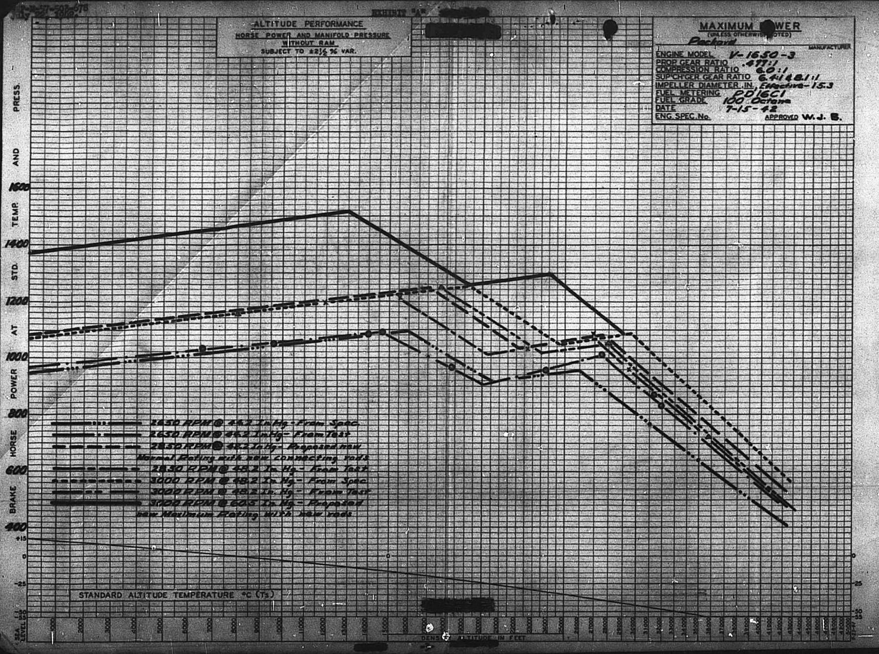
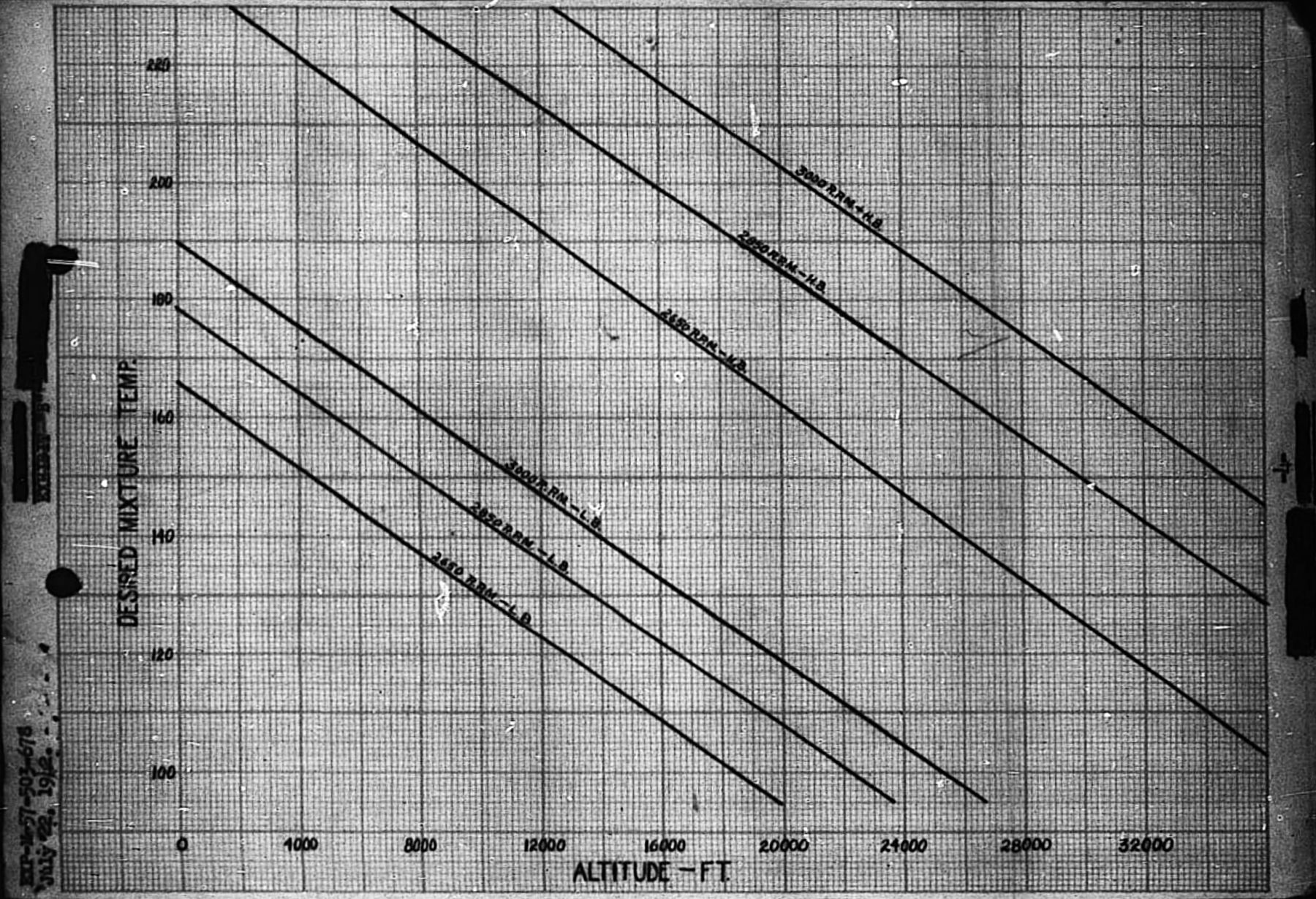
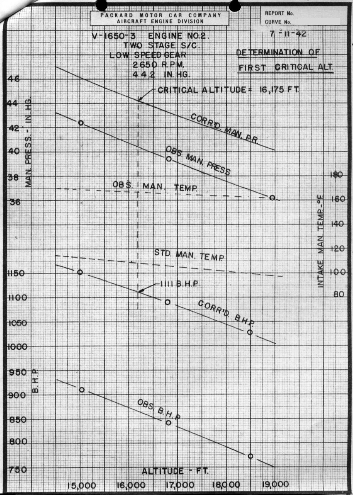
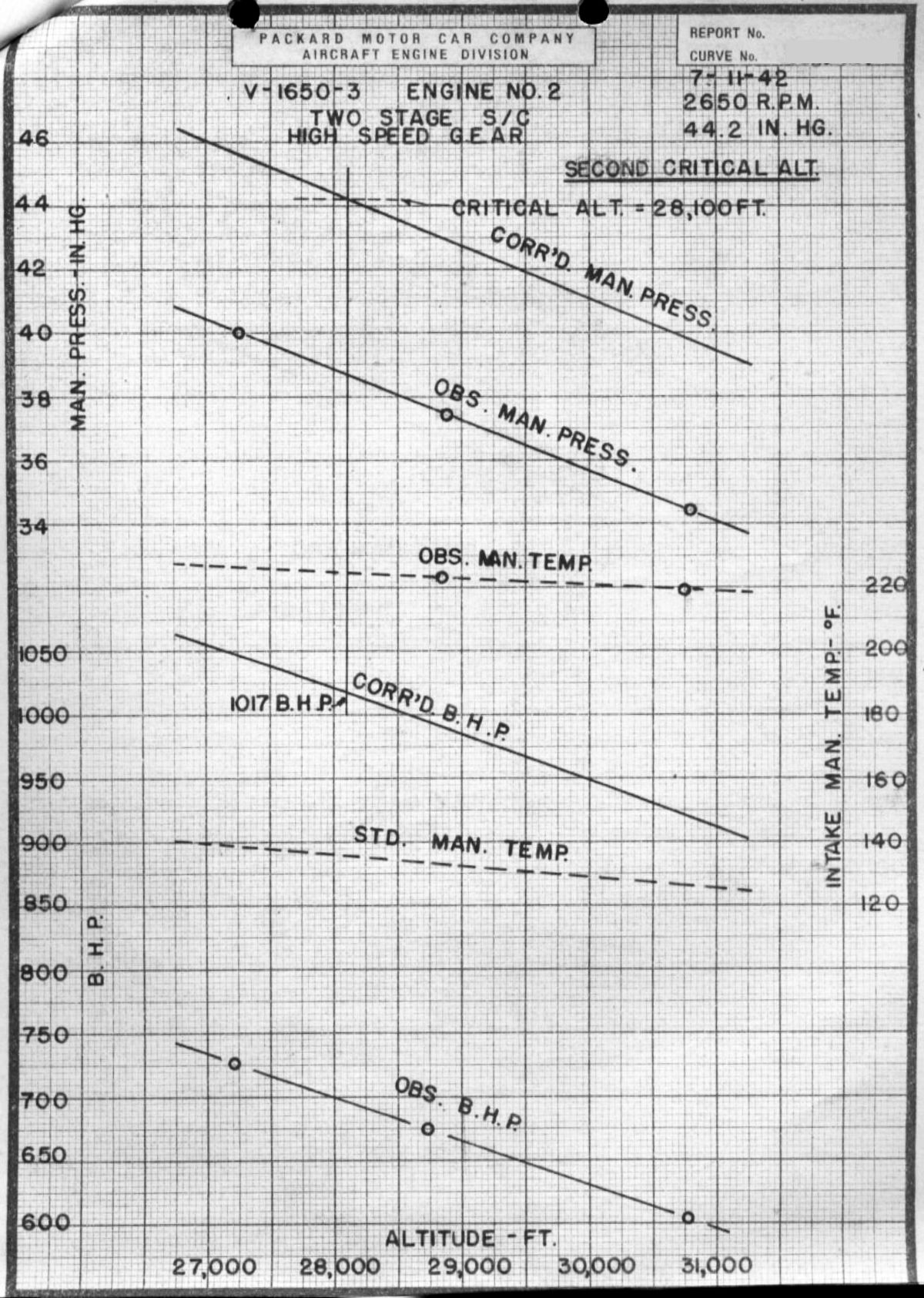
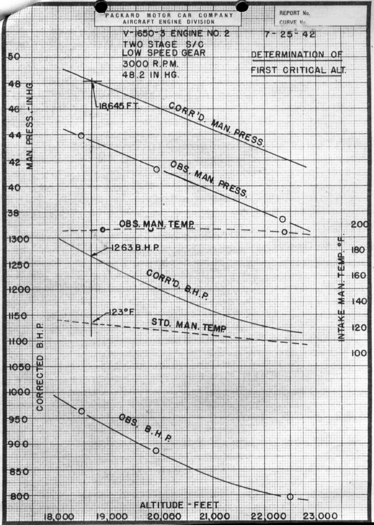
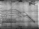
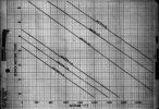
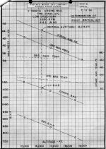
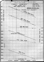
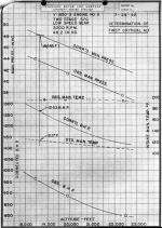
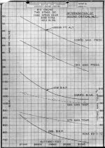
22 Jul 1942. PPL civilian test engineer Willis J. Brown reported on V-1650-3, AF No. 41-46948, altitude performance checks. Wright Field had received the engine on 22 Jun 1942. It was installed in dynamometer No. 11 with the necessary equipment to simulate altitude conditions. The test was completed on 9 Jul 1942. The V-1650-3 was similar to the V-1650-1 except that it had a two-stage, two-speed supercharger with an aftercooler and redesigned connecting rods to withstand the higher imep. It was modeled after the R-R Merlin 61 but used a Packard-designed supercharger drive and a Bendix-Stromberg carburetor instead of an S.U. carburetor. However, the engine tested did not incorporate the heavier connecting rods so no test could be run to check output at 60.5 inHgA and 3,000 rpm in both low and high speed supercharger gears. PM5Fig. 4 and PM5Fig. 5 depict the altitude test results and the following table lists the output obtained at various critical altitudes.
| rpm | bhp | Manifold
Pressure
(inHgA) | Mixture
Temperature
(°F) | Altitude
(ft) |
|---|
| Low Speed Supercharger Gear |
| 2,650 | 1,090 | 44.2 | 114 | 14,700 |
| 2,850 | 1,240 | 48.2 | 117 | 17,400 |
| 3,000 | 1,250 | 48.2 | 127 | 17,700 |
| High Speed Supercharger Gear |
| 2,650 | 1,010 | 44.2 | 135 | 27,600 |
| 2,850 | 1,090 | 48.2 | 160 | 27,000 |
| 3,000 | 1,050 | 48.2 | 174 | 28,000 |
Performance shown in both the table and the PM5Fig.4 are based on best power mixture. This was obtained by leaning the carburetor. The mixture temperature used was determined by Packard from a supercharger test by the following formula:
Tm = Ta + 2/3(At - 40) where
Tm = manifold temperature, °F
Ta = atmospheric temperature, °F
At = uncooled temperature determined from supercharger
40°F was the fuel vaporization temperature drop
PM05Fig. 5 was a curve of desired mixture temperature as determined by Packard.
Upon altitude performance check completion, a check was run on the carburetor in an attempt to obtain the desired mixtures in automatic rich. A 6,000 cc automatic lean jet; 2,500 cc enrichment jet; No. 34 auto rich jet; and an automatic mixture compensator unit with a "Y" needle set at 29.1 inH2O at 7,500 ft were installed. At the time this was considered satisfactory, but it was later found that the carburetor richened considerably at altitudes above 30,000 ft. PM05Fig. 4 indicated that the engine was low in altitude at both 2,850 and 3,000 rpm. This was probably due to the small Bendix-Stromberg carburetor size as compared to the S.U.; Brown opined that increasing the venturi diameter might regain some altitude. [22 Jul 1942 Memorandum Report EXP-M-57-503-678. Preliminary Altitude Performance Check on V-1650-3 Engine. P192626.]
23 Jul 1942. Maj A.F. Wentzel, Chief, Technical Control Branch, Inspection Section, wrote the Packard AAFRR after noticing that V-1650 Development Program Progress Report No. 141 dated 17 Jul 1942 had stated that Packard was assembling an engine with Hastings and McQuay-Morris piston rings with the intention of running the equivalent of a 15-hr model test in order to obtain approval for these manufacturers to become alternate supply sources. Maj Wentzel advised that only under exception circumstances would MatCmd approve alternate sources, and only after satisfactory completion of an official model test in accordance with Specification AN-9502a. [Letter, Maj Wentzel to Packard AAFRR. 271]
25 Jul 1942. Packard Assistant Service Manager, C.H. Vincent, wrote Production Engineering Memorandum No. 5 to Production Engineering Section Chief Col O.R. Cook regarding V-1650-1 engines advising the following:
As stated in the Packard letter of 19 Jun 1942, the information came from a current issue of the BAC handbook and the writer was advised that the prohibition was due to detonation danger. Since that, Packard tests had shown that detonation was unlikely, even with a 61 inHgA manifold pressure. Ellor had cabled England and was advised that R-R had limited the use of emergency boost control to low blower only because excessive pressures were produced when the control was operated with high-speed blower. R-R suspected that might be true of Packard engines after the automatic control had been recalibrated, and tests recently completed at Curtiss-Wright indicated that they were not. Lt Kinkade revealed that recent Wright Field tests gave about the same results. Consequently, a bulletin authorizing the use of both blower speeds was under preparation, although it would not be released until actual data had been released by Wright Field. [Letter, C.H. Vincent to Col O.R. Cook. 268.]
25 Jul 1942. Lt Kinkade commented on unsatisfactory report No. 42-143 dated 9 May 1942 and concluded that a blade rod bolt in the No. 1 cylinder exhibited a typical fatigue failure. He recommended no further action than to file the report for reference purposes.
The pilot reported that the V-1650-1 engine, AAF No. 41-46714, was functioning normally prior to takeoff. After a magneto check and upon opening the throttle for takeoff a sudden violent clanking noise was accompanied by smoke. He cut the throttle and switches immediately. The engine had thrown a rod in Nos. 1 and 2 cylinders on the B-bank (left) and Nos. 2 and 3 cylinders on the A-bank; total engine time was 20:25 hrs.
Packard examined the engine and reported that the No.1 blade connecting rod bolt, PN 600504, was found broken 0.906" from under the bolt head in the heavy section. The fracture was clean and even, with the appearance of a fatigue failure. The companion blade bolt was broken in the lighter section of an apparent tension failure. The No. 1 blade connecting rod had broken in the "I" section. The upper part remained with the piston and pin, but the lower part had broken into small pieces that were scattered toward the crankcase rear. The No. 2 fork rod, PN 600511, was broken in the "I" section; the upper part remained with the piston and pin but the lower part had separated from the PN 600521 bearing block and the PN 500522 bearing cap by breaking the forked-rod bolts, PN 600516, was thrown through the crankcase B-side. The PN 600611 forked rod bolt holes were not broken. Heavy fretting evidence was found between the fork rod and fork rod bearing block. The No. 1 fork rod bearing block and bearing cap, badly distorted, were found in the crankcase rear. The No. 2 blade connecting rod, PN 600501, was broken in the "I" section, with the blade rod lower part turned around the fork rod, PN 600511. When the engine stopped the blade rod was protruding through the B-bank, although it was normally in the A-bank. The No. 2 fork rod bolt hole rear was broken off and the right rear fork rod bolt, PN 600516, was broken off at the nut (PN 600517) split line and the fork rod bearing cap, PN 600522. Both blade and fork connecting rods remained on the crankshaft journal. This failure was blamed on the migration of the loose No. 1 parts migrating to the crankcase rear.
The No. 3 right rear fork rod was broken off at the nut and bearing cap split line. Nos. 4, 5 and 6 connecting rod assemblies were intact. All engine bearings were well lubricated. No evidence of excess heat could be found anywhere in the engine. Both failed rod assemblies and the PN 604084 gear pinion driving shaft were magnafluxed and found satisfactory. Connecting rod bolt breakage had occurred in the dowell position as evidenced in the R-R Technical Instruction Sheet dated 7 Sep 1941:
Technical Instruction Sheet BY.19
The following facts must be kept clearly in view when tightening connecting rod bolts on Kestrel or Merlin engines. These remarks do not apply, however, to vulture if and when this demands attention.
a. Bolt material and heat treatment has been selected with the object of making it impossible to do damage by over-tightening the bolt, even if the bolt be tightened up to the extent of taking a permanent set. Even 0.015" permanent extension will not react upon the engine's safety or reliability.
b. It is of the utmost importance that connecting rod bolts on the above engines should be fully tightened.
c. Under no conditions must a nut be turned back to insert the split pin. However slight the amount is that the nut has gone beyond the correct position, the next serration must be used, that is, the nut and bolt tightened up and never slacked back.
d. There had been one or two failures of bolts on the increased fitting diameter between the two cap halves. These failures, which were very few (two or three in number) were definitely shown to be due to the bolt not being completely tightened. The correct spanner and tommy bar must be used as by using these, ductility covers the difference a normal man and a very strong man, as if the man with the extra strength goes little beyond the maximum, the bolt stretched and readjusts itself, due to its ductility, to the new conditions. The above also applies to angular twist. A 45° twist is not a danger, as tests have proved the steel characteristics had not deteriorated, the only effect being a slight increase of tenacity and a very slight ductility drop.
[25 Jul 1942 Memorandum Report U-EXP-M-57-8383. Failure of Blade Connecting Rod Bolt, Part No. 600504, V-1650-1 Engine, A.F. No. 41-46714. P171763.]
1 Aug 1942. Col Carroll gave MatCmd approval to use the war emergency power valve in both high and low blower on the V-1650-1 engine. [Telegram EXP-7768, Col Carroll to Packard. 285.]
1 Aug 1942. On 5 May 1942, Bolling Field had submitted Unsatisfactory Report No. 42-57, Air Service Command Serial No. 42-7015, which stated that exhaust port studs were too short to accommodate lock washers called for in Technical Order No. 02-55AA-4. Engine vibration was causing the nuts to loosen. Packard had issued Service Bulletin No. 42-30-B28 on 26 Jun 1942, which called for replacement of the stepped exhaust flange studs with straight studs that were longer and larger in diameter; lock plates would be used to secure the nuts. MatCmd recommended that technical instructions be issued to implement the Packard Bulletin. [1 Aug 1942 Memorandum Report U-EXP-M-57-8415. Exhaust Flange Hold-down Nuts, V-1650-1 Engines .P171965.]
4 Aug 1942. The Production Engineering Chief alerted the Industrial Planning Section that he had telegraphed Packard requesting a list of machine tools necessary to convert 225 engines on the schedule from V-1650-1 to V-1650-3. The list, along with pertinent data, was to be submitted to the Industrial Planning Section, Production Division, Materiel Center as soon as practicable in order that necessary processing could begin. He requested that the Industrial Planning Section expedite facilities processing in order to meet the 225 V-1650-3 engines per month. This planned production was not in addition to present planned Packard engine deliveries. This project was of prime importance and all effort necessary was to be taken to make the facilities available as soon as possible. [Cross Reference – Contract Files AC-22784 and AC-15678. 289.]
4 Aug 1942. Maj Wentzel wrote the Packard AAFRR, referring to Progress Report No. 6 dated 1 Aug 1942 on Merlin 28 engine British Type Test. Maj Wentzel informed the AAFRR that it was the responsibility of the model test engineers to determine that the test was fun to the schedule furnished them and to report the progress and results of the test. Actual responsibility was not well defined, but the duties here outlined were considered sufficient under the circumstances. [Letter, Maj Wentzel to Packard AAFRR. 290.]
5 Aug 1942. Production Engineering Chief Brig Gen K.B. Wolfe notified the District Supervisor, Eastern Procurement District, New York, that the Cuno Engineering Corporation of Meriden, Connecticut was failing to deliver Cuno filters required as production parts of V-1650 engines. Gen Wolfe requested that the matter be investigated, the manufacturing deficiencies be alleviated and Cuno extend the proper cooperation to Packard. [Cross Reference Contract Files W-535-ac-15678. 291.]
6 Aug 1942. A large conference at Wright Field that included representatives from Packard, Bendix-Stromberg, Curtiss-Wright and MatCmd was convened to address P-40F and V-1650-1 difficulties.
a. Carburetors. Curtiss had difficulty with engines running either extremely rich or not at all due to sticking carburetor poppet valves. In some instances the engine could only be operated with the mixture control in idle cut-off. Practice at that time was to fill the carburetors with fuel eight hours before operation; this was not being done because of production practices and the fire hazard. Curtiss objected to the early carburetor filling because Allison engines with similar carburetors gave no trouble under the same conditions. Since several troublesome carburetors checked perfectly on the factory test bench, Bendix agreed to supply kits for checking bad carburetors at Curtiss while they were still on the engine. The oil used at Packard to prepare carburetors for shipment was a potential trouble source and the MatCmd PPL Carburetor Unit was tasked to check this oil for any content that might be detrimental to the carburetor function.
b. Spark Plugs. Service plugs had a tendency to foul due to engine over-priming before starting. Considerable fuel and oil got into the plugs before they warmed up, leading to the fouling. Curtiss was preparing a revised starting procedure, which was to be issued soon. New plugs with improved clearing properties were under development
c. Propeller. There were numerous propeller trouble reports from the field of automatic propeller control loss due mainly to sticking safety switches. Carbon particles had become embedded between the propeller governor piston and cylinder wall because due to a chamfer on the piston top. Curtiss was instructed to eliminate the chamfer. The propeller governor gasket screen eliminated governor troubles if it was serviced every 10 hrs. Eliminating the low pressure safety switch was considered because oil pressure loss should set the propeller in low-pitch to the governor construction if the safety switch was inoperative. However, during dives at Curtiss with low oil pressure and the safety switch blocked, the propeller pitch did not decrease. Nothing was decided.
d. Propeller Governor Removal. Curtiss had tried a propeller spinner with enlarged bulkhead holes to facilitate governor removal and reported a crew could remove and reinstall the governor in two hours. The spinner balance was being checked before any further action.
e. Header Tank Relief Valve. New relief valves incorporated a 6 lb spring in place of the old 2.5 lb spring. Sticking thermostats in the field were resulting in coolant loss of up to 7 gal when the 70-30% glycol/water mix was used. By closing the shutters and gunning the engine, quick coolant heating minimized loss due to better valve seating. Instructions were to be sent for servicing units in the field that were prone to sticking.
f. Header Tanks. Curtiss was working on a shortened header tank made of thicker material in order to improve the tank durability and facilitate changing propeller governors in the field.
g. Coolant Pumps. Packard was developing a pump with a redesigned seal to address chronic coolant leaks. Instructions on servicing coolant pumps without removing radiators had been written and would be disseminated. Packard was to supply a 2 lb coolant pump packing grease AC-3599 (Socony-Vacuum Intava PD-403-H) can with each new engine equipped with the present pump design.
h. Magnetos. Accumulated moisture was impacting magneto reliability. Water was frequently found in magneto distributor blocks' two lower recesses. Suggestions included drilling the recesses to allow moisture drainage and larger vent holes using trap and screen vents similar to those used in Scintilla magnetos. A special ignition harness with distributor connection cover vent holes at the lowest point instead of on the side were being tested by the PPL. Packard and Curtiss were to confer with magneto engineers at Buffalo, New York.
i. Quadrant. Curtiss was flight testing a new quadrant design that incorporated one friction nut for the throttle only and another for the mixture and propeller controls. No friction lock was used on the supercharger or war boost controls.
j. Throttle Lag. While flight testing had revealed no noticeable lag in the boost control system the throttle control had very noticeable lag.
k. Radiators. Honeycomb radiators could be easily serviced while tubular units were very difficult, if not impossible, to repair. The radiator type used by the British was to be investigated.
l. Air Scoop. A campaign on air temperature control butterflies in the field was under way. A service bulletin had been released to address this upgrade.
m. Cowl Flaps. Curtiss was to flight test a three-position switch with limit controls. Curtiss suggested using mechanical flaps instead of electric controls in view of the increased speed and positive control.
n. Connecting Rod Bolts. Tightening stretch limits were to be held at 0.005" – 0.008" until the MatCmd Materials Laboratory could check a report on exceeding the elastic limit on bolts with more tolerance.
[19 Aug 1942 Memorandum Report U-EXP-M-57-8475-1. Service and Operation Difficulties with P-40F Airplanes and Packard V-1650 Engines. 322 – 326, P172244.]
6 Aug 1942. A conference held at MatCmd included Col E.R. Page, Opie Chenoweth, E.A. Wolfe and W.J. Brown representing MatCmd, R.N. DuBois representing Packard, and J.E. Ellor representing the British Air Commission. The group decided not to run the first V-1650-3 model test as originally intended, but instead to run a special safety test so the engine could be released for flight. To facilitate this, Lodge spark plugs were to be furnished by Packard, with one set being sent to NAA and the other to Curtiss for the engine to be installed in the XP-60. The special safety test was to be 55 hrs in duration according to a special schedule. At the test's completion the engine was to be returned to Packard for use in supercharger rig testing. This would necessitate obtaining an additional engine incorporating all improvements identified by the special test for a model test, which was to be run at completion of rig testing. The group thought that several additional V-1650-3 engines would probably be necessary before the development program was complete. Packard was directed to furnish a proposal for 2, 4, 6, 8, 10, 12 and 14 additional engines along with a delivery schedule so MatCmd could decide how many engine to purchase. Col Page stated that the Merlin 61 engine, which was being shipped from England, would be delivered to the PPL and held for any testing found necessary in the future. He suggested that if Ellor felt tat at any time the engine could be use to expedite the development program he should ask the BAC to Contact Gen Echols and ask for the engine's use
Packard V-1650-3 Testing Schedule
| Run No. | Accum
Time
(hrs) | Period
Time
(hrs) | Running
Type | MP (inHgA) | rpm | SC Gear | Throttle | Coolant
Outlet
Temp (°F) | Desired
Temp Rise*
(°F) |
|---|
| Altitude Dynamometer |
| 1 | 5 | 5 | Cont | 44.2 | 2,650 | Low | Full | 194 | 100 |
| 2 | 10 | 5 | Cont | 44.2 | 2,650 | High | Full | 194 | 180 |
| 3 | 15 | 5 | Cont | (1) | 2,570 | High | Full | 194 | 168 |
| 4 | 25 | 10 | Alternate | | | | | | |
| | | | 5 min | (1) | 2,650 | High | Part | 194 | 180 |
| | | | 5 min | (1) | 2,650 | Low | Part (2) | 194 | 100 |
| 5 | 30 | 5 | Alternate | | | | | | |
| | | | 15 min | 60.12 | 3,000 | High | Full | 250 | 232 |
| | | | 30 min | 236(2) | 1,700 | High | Part | 194 | - |
| 6 | 32.5 | 2.5 | Alternate | | | | | | |
| | | | 15 min | 54.3 | 2,850 | High | Full | 250 | 206 |
| | | | 30 min | 276(2) | 1,600 | High | Part | 194 | - |
| 7 | 37.5 | 5 | Alternate | | | | | | |
| | | | 15 min | 60.2 | 3,000 | Low | Full | 250 | 135 |
| | | | 30 min | 276(2) | 1,700 | Low | Part | 194 | - |
| 8 | 40 | 2.5 | Alternate | | | | | | |
| | | | 15 min | 54.3 | 2,850 | Low | Full | | 120 |
| | | | 30 min | 225(2) | 1,600 | Low | Part | | - |
| Torque Stand Running |
| 9 | 55 | 15 | Alternate | | | | | | |
| | | | 5 min | 1,300(2) | 3,000 | Low | Part | 250 | 135 |
| | | | 10 min | Prop | 610 | Low | Part | 194 | - |
| Notes: | * Including Aftercooler |
| | (1) Manifold pressure required to develop 90% of the power obtained from run 2. |
| | (2) Manifold pressure required to develop the power listed. |
[10 Aug 1942 Memorandum Report EXP-M-57-503-689. Conference on Program for Development of V-1650-3 Engine. P192592.]
 |
| Failed Valve |
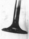
6 Aug 1942. On 22 May 1942, Harding Field, Baton Rough, Louisiana, submitted Unsatisfactory Report No. 42-77, Air Service Command Serial No. 42-8072 about a failed V-1650-1 intake valve, PN 600440. This valve used AMS 5700 valve steel for the stem and head, P.M. 781 – AMS 5682 chromium nickel alloy for the seat, and P.M. 110 – SAE 1095 steel for the tip. It had been in service for 72:35 hrs. The valve head fracture appeared to have resulted from fatigue, with the fracture starting at a point in the head heavy section and progressing toward the seat. This was a secondary failure with respect to one of a number of radial cracks that had begun at the valve head seat. The fractures obtained by opening the radial cracks was coarse and crystalline in the deposited seat material zone, whereas that of the valve material was definitely of the progressive fatigue type. Microscopic radial crack examination revealed the defects extended in a transgranular continuous manner from the chromium-nickel deposited metal that terminated at the boundary between the valve and steel material. This circumstance and the appearance of the fracture indicate that the primary failure was due to a fracture, probably by impact, of the deposited seat material. The submitted valve was a PN 600440, a part superseded by PN 600443, which was redesigned to provide for a considerably heavier section in the seat and a modified distribution of the deposited chromium-nickel seat material. There were no failure reports for the new design. [6 Aug 1942 Memorandum Report U-EXP-M-57-8318-M. Intake Valve from Packard V-1650-1 Engine, AAF No. 41-46569 .P171644.]
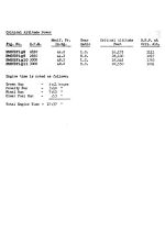
8 Aug 1942. V-1650-3 No. B-2 was tested before shipment to Curtis Wright to document its performance. The sea level power was somewhat higher than the first one tested. Altitude performance was satisfactory though the critical altitude was somewhat lower than B-1. Results compared favorably with the British predicted performance and Wright Field's test of the B-1 engine. The British-built heavy connecting rods were to be replaced with American-built heavy rods when it was returned from Curtiss-Wright. The carburetor was still not the correct one and was to be replaced with the latest type.
V-1650-3 SN B-2 combined the power section and reduction gear of V-1650-1 SN A-2313 with British-built Merlin 61 heavy connecting rods, the Packard-built two-stage two-speed supercharger and an aftercooler manufactured by the Harrison Radiator Corporation to Packard drawings. The carburetor was a Bendix-Stromberg PD-16C1, SN 82211, formerly used on the SN B-1 engine, and only used for the final acceptance run, having a 4" diameter main venturi instead of the standard 3.406" diameter venturi. During the initial and penalty run the aftercooler used was the original one for No. B-2. The B-1 aftercooler was used for the final run and was shipped with the engine. The high-altitude magnetos were by North East Electric Company of Rochester, New York, with the "A" magneto type X-180515, SN 1, and the "B" magneto type X-160579, SN 2.
The engine was mounted on the 2,700 hp dynamometer with the aftercooler coolant system in operation using standard coolant. The front supercharger bearing temperature was taken only during the green run-in. Maximum carburetor and aftercooler cooling was used at all times except the final altitude runs when control was tried. For the running, AC LS-47 spark plugs were used. Fuel was 100 octane gasoline conforming to Specification AN-VV-F-781; oil used conformed to Specification AN-9532, Grade 1100.
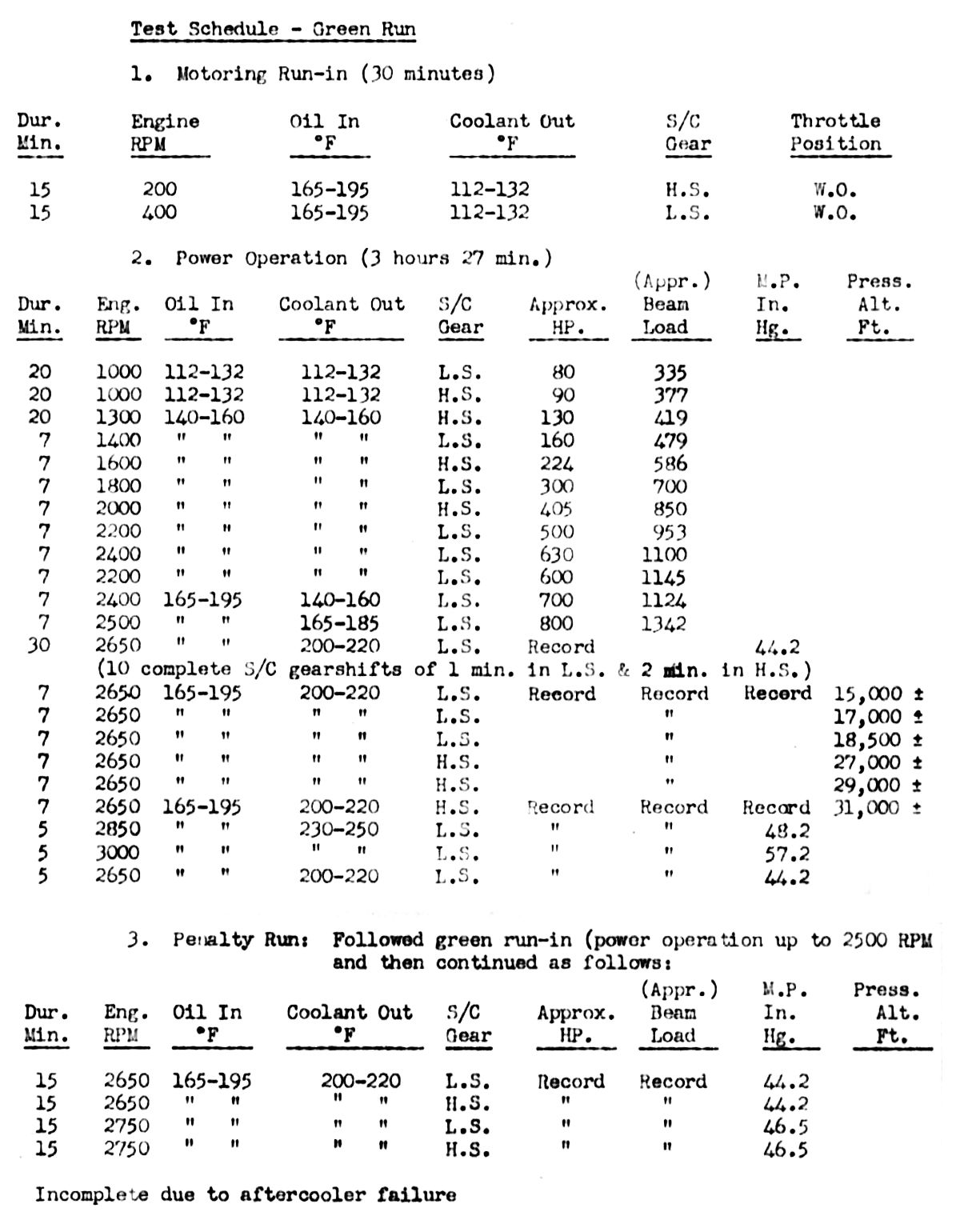
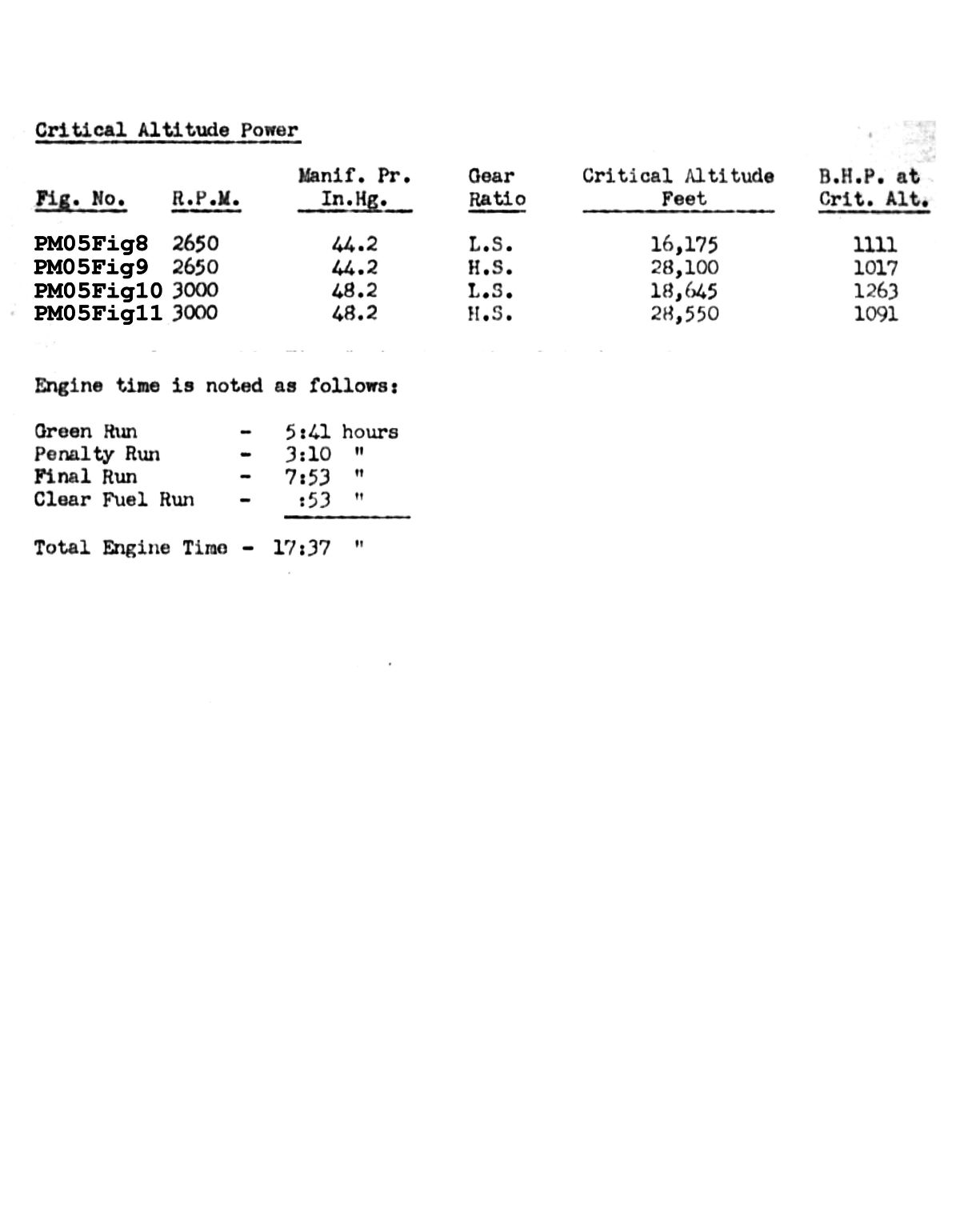
The engine was subjected to a 30 min motoring-in period, a 3:27 hr green run under power, a penalty run, and a final run. Although the report provided a log of power settings, temperatures, supercharger gear selections, pressure altitude and approximate power output for each running period, these details are omitted in this account.
When the engine was started the magnetos were out of time. The test crew established that mounting the North East magnetos was difficult because of their construction and that the second-magneto timing process was prone to pull the drive between the two magnetos out of its resting place, thereby changing the first magneto timing. When altitude checks were made during the green run, the supercharger gear shift was not operating properly, and the test team decided to remove the supercharger and inspect it. The PN 601798 center bearing had been omitted from the intermediate impeller drive next to the PN 601791 impeller driving gear. As a result the following parts required replacement:
| Part No. | Quatity | Name |
|---|
| 601808 | 9 | Drive Clutch Plate |
| 601807 | 12 | Friction Multi-Plate Clutch |
| 601810 | 3 | Housing to Clutch Plates |
| 601806 | 3 | Clutch Plate Disc Adapter |
| 601875 | 1 | Release Spring Clutch |
| 601876 | 3 | Spring Thrust Washer |
After the green run, teardown inspection revealed propeller reduction gear scuffing, as had frequently been encountered on production engines, necessitating replacement of the gear and pinion. Three PN 601795 supercharger drive planet gears were replaced with the lighter PN 607883 gear. Replacement of these parts caused a penalty run, during which the aftercooler sprang a coolant leak and sucked the mercury out of the manometer used to measure pressure drop across the aftercooler coolant system (pump inlet to aftercooler outlet. The B-1 engine aftercooler radiator was substituted for the final run.
For the final run, carburetor No. 26211, which had been on B-1 engine and sent to Bendix for calibration, was used. At the completion of the low speed supercharger gear ratio altitude runs, the aftercooler was removed and the plates lapped to address charge leakage. The wheelcase to crankcase gasket was also replaced because it had blown. The aftercooler was again removed and its plates lapped after completion of the altitude runs in high speed gear ratio. Apparently it was still leaking or had begun leaking anew. In repairing a leaky auxiliary oil line serving the tail shaft bearing, the fitting threads were stripped, requiring carburetor elbow replacement. [Packard Report No. 66. Testing or Egine NO. B-2 Type V-1650-3 Before Shipment to Curtiss-Wright Corporation. 294 – 304.]
Packard V-1650-3 Test Schedule and Performance
 |
 |
 |
 |
 |
 |
| PM05Fig. 6. |
PM05Fig. 7. |
PM05Fig. 8. |
PM05Fig. 9. |
PM05Fig. 10. |
PM05Fig. 11. |
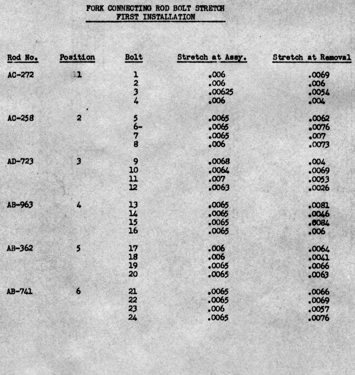
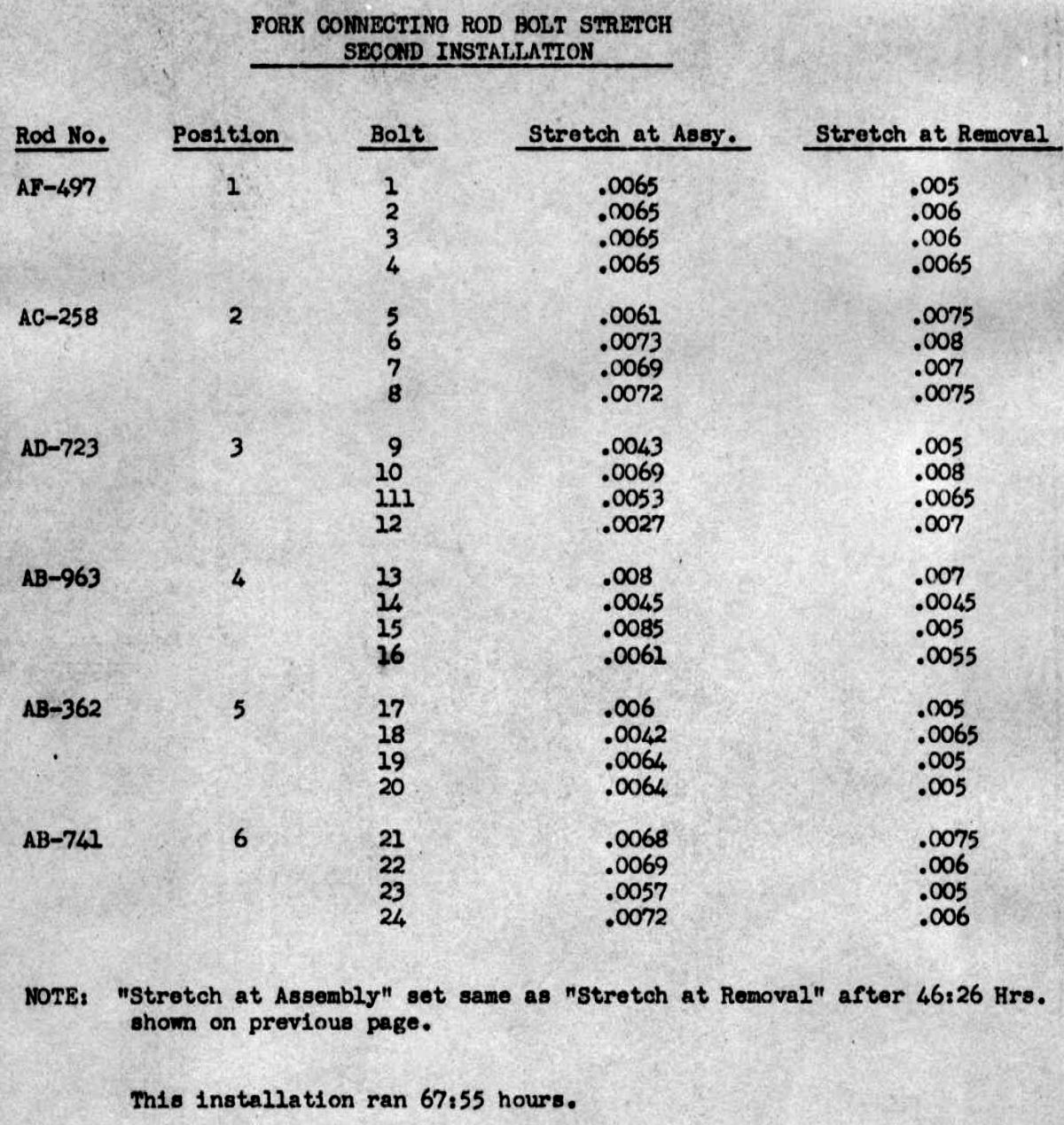
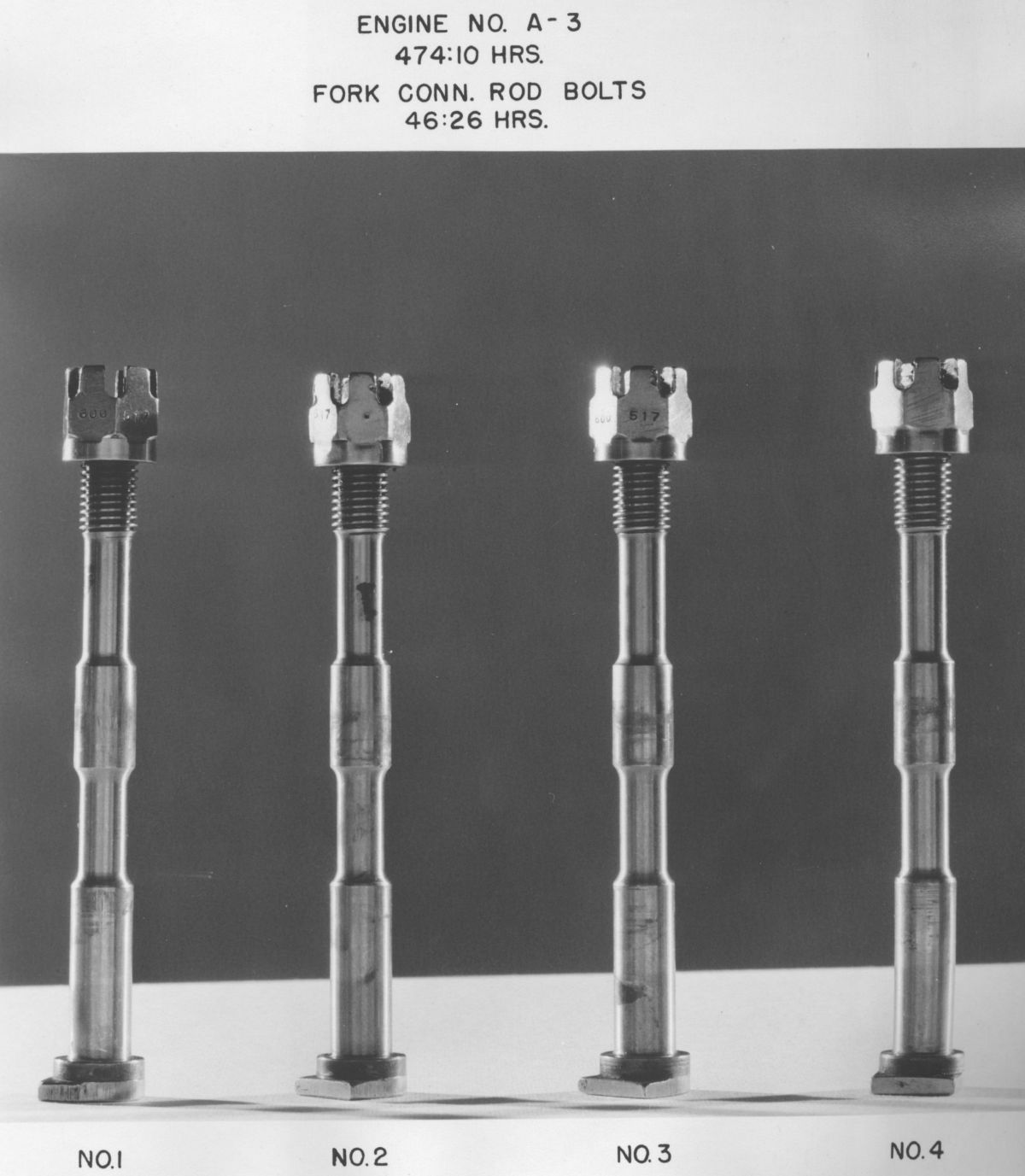
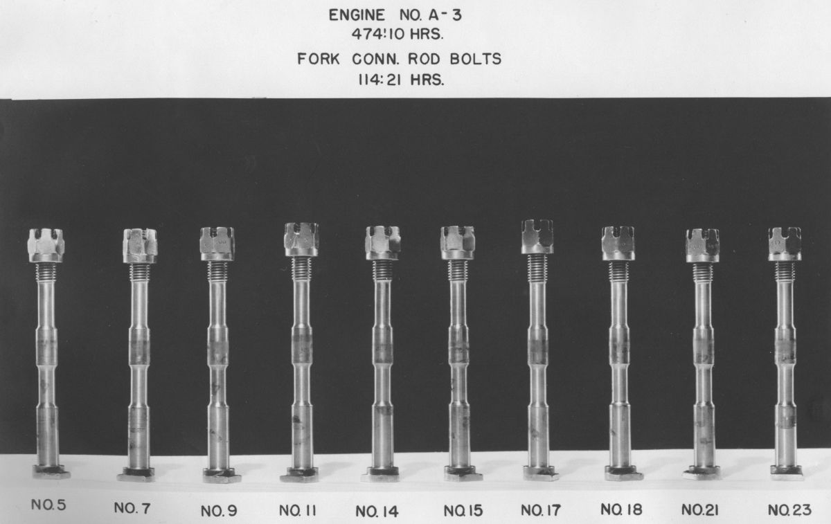
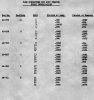
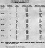
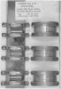
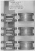
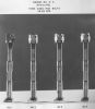
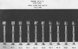
11 Aug 1942. Due to several PN 600511 connecting rods having failed in the Packard Engineering Department and in service, connecting rods were being assembled with the bolts torqued to a specified stretch rather than torque. This was intended to reduce fretting between the fork connecting rod and upper bearing block by maintaining uniform pressure on the parts. Report RR-50 covered the effect of bolt stretch. A connecting rods batch that was being withheld from production because the bolt holes were misaligned with the upper bearing block holes; the Inspection Department requested that these rods be tested to determine how much misalignment was detrimental to the rod endurance qualities. It was found that connecting rods installed with a specified stretch showed a marked reduction in fretting between the PN 600510 rod and PN 605021 upper bearing block; this method was recommended for production using 0.006" – 0.010" stretch in the PN 600516 fork rod bolt and PN 600504 blade rod bolt. Fork connecting rods misaligned no more than 0.0008" were acceptable for production.
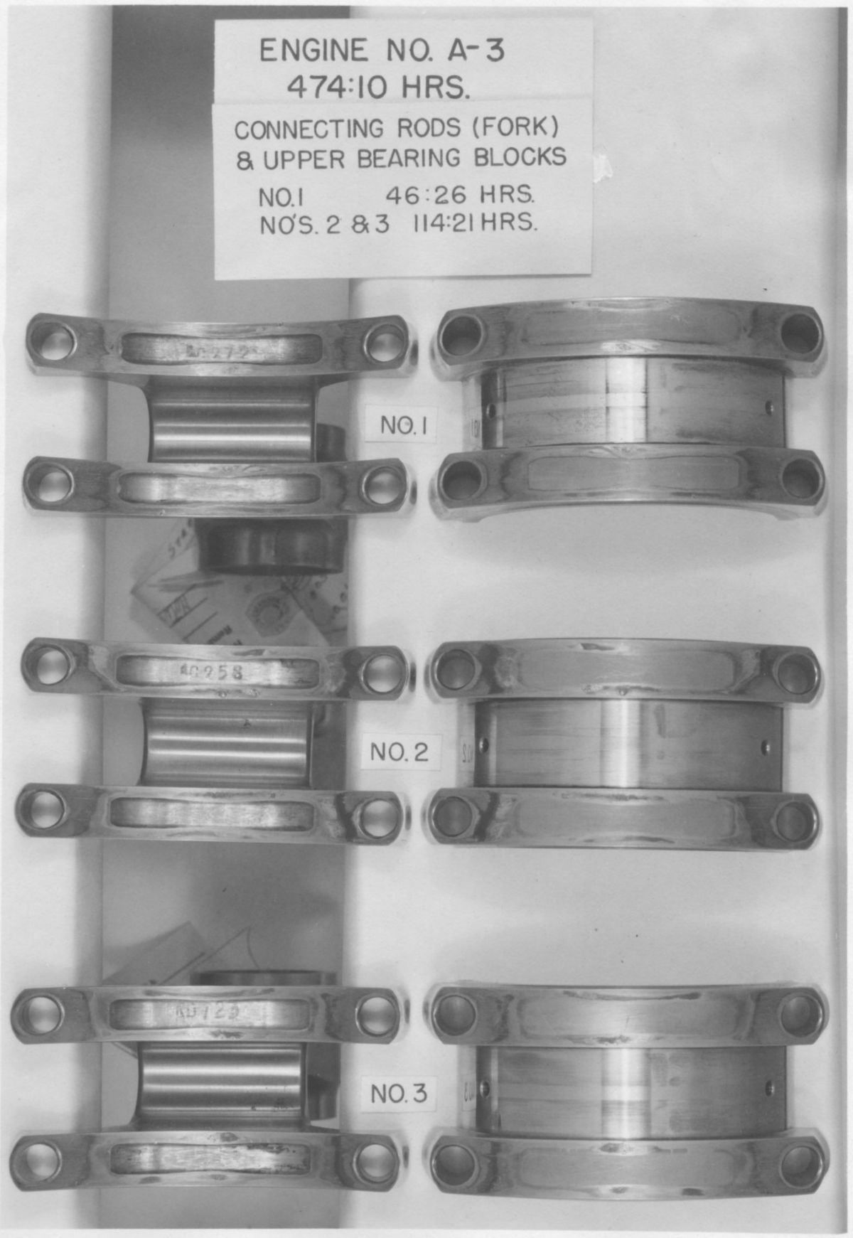
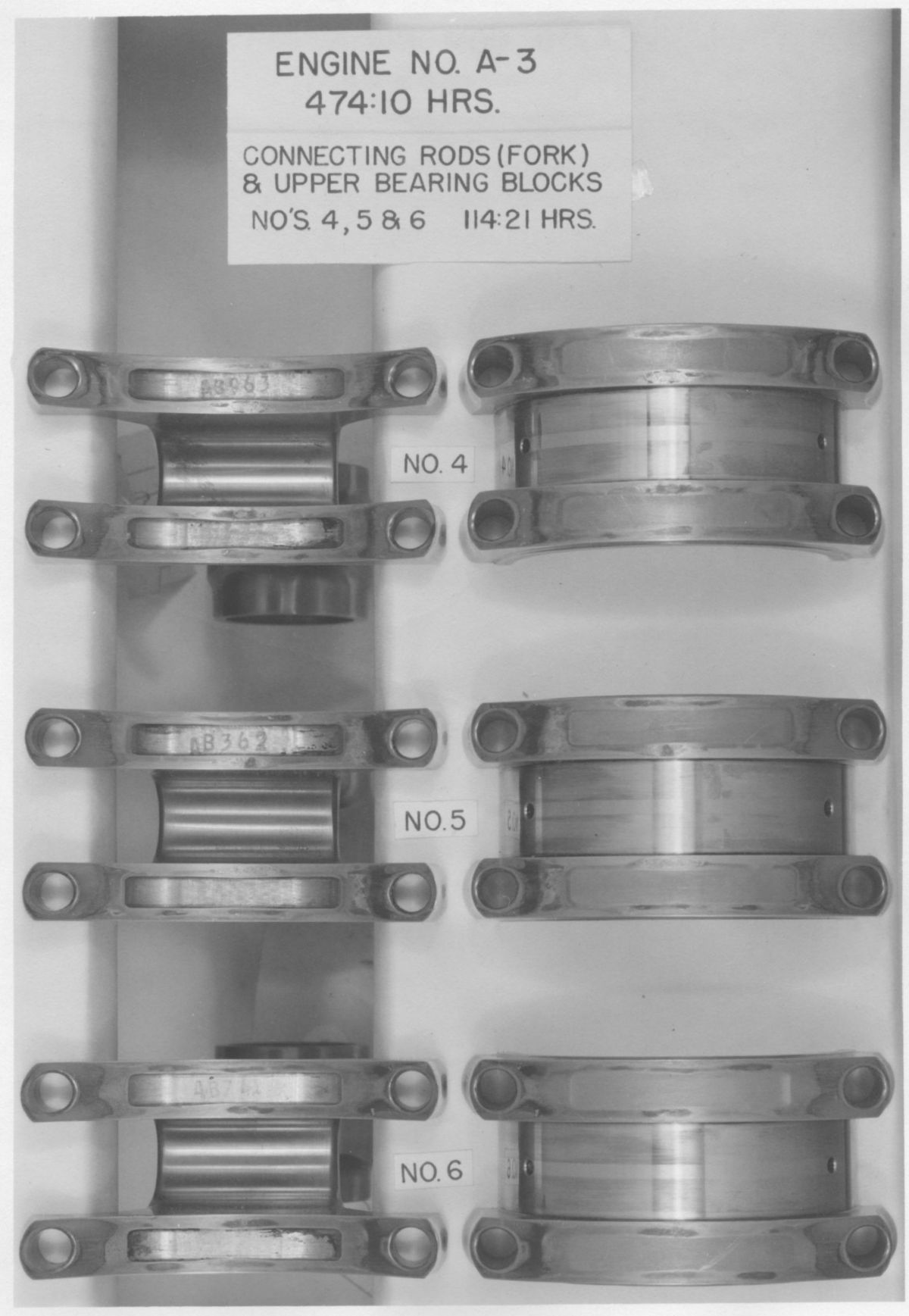
Alignment of the four rod holes with the bearing block holes was checked by inserting plugs through the rod holes into the bearing block holes. Holes that were in proper alignment had 0.360" +0.0003" -0.0000" diameters while misaligned holes only accepted smaller plugs. The six connecting rod pairs used in this test required plugs ranging in diameter from 0.3592" to 0.3597" (0.003" – 0.0008" undersize). The blade rods were units from stock that were unremarkable except for installation with a specified bolt stretch. These rod sets were installed in an engine using standard connecting rod bolts. All rod pairs completed 114:21 hrs except for No. 1, which was replaced after the No 4 A-bank intake valve failed.
Initial and Final Rod Condition
Rod #AC 272, used in No. 1 position, required a 0.3594" plug when checking hole alignment, ran 114:21 hrs, and had only slight fretting on both arches. It was removed because the blade rod journal was out of round after the valve failure. Rod #AC 258, used in No. 2 position, required a 0.3592" plug when checking hole alignment, ran 114:21 hrs, and had moderate fretting on both arches and slight fretting at one bolt hole. Rod #AC 723, used in No. 3 position ran 114:21 hrs, had slight fretting on both arches. Rod #AC 963, used in No. 4 position, required a 0.3596" plug when checking hole alignment, ran 114:21 hrs, and had moderate fretting on both arches and slight fretting at one bolt hole. Rod #AC 362, used in No. 5 position, required a 0.3592" plug when checking hole alignment, ran 114:21 hrs, and had moderate fretting on both arches and slight fretting at one bolt hole. Rod #AC 741, used in No. 6 position, required a 0.3594" plug when checking hole alignment, ran 114:21 hrs, and had slight fretting on both arches and at one bolt hole. Rod #AF 497 replaced the original No. 1 position rod #AC 272. This was a standard rod, obtained from the production bond room and had 67:55 hrs time. When removed it had some fretting on both arches and slight fretting at one bolt hole. Visual inspection of all rods that completed the test showed them to be in comparable condition. Magnaflux inspection showed no crack indications. [Packard Report No. 65. Connecting Rod Bolt Stretch and Fork Rods with Bolt holes in Misalignment. 306 – 316.] The British Air Commission suggested lubricating the area between the forked connecting rod arches and bearing blocks. [29 Aug 1942 Cross Reference 452.8, Packard Merlin Engine. 332.]
Connecting Rod Bolt Stretch Data
 |
 |
 |
 |
 |
 |
19 Aug 1942. During a conference at MatCmd attended by Col Page, Col Carlson, Chenoweth and Brown representing MatCmd, and E.H. Smith representing Packard, the possibility of obtaining a downdraft carburetor for use with the V-1650-3 was discussed. The general opinion was that some experimental work should be done with a downdraft carburetor, and Col Page instructed Smith to submit a proposal for two downdraft carburetors and the necessary parts for equipping two V-1650-3 engines.
Smith stated that it would be uneconomical from both a money and time perspective to build more than two additional V-1650-3 engines beyond those already on order with existing facilities; more engines would require additional tooling. He stated that if only two additional engines were ordered the first could be delivered 1 Jan 1943 and the second 1 Feb 1943 provided Packard was given a letter of intent by 1 Sep 1942 allowing these two engines to be built along with the one ordered by the British Air Commission. Smith was instructed to submit a proposal for two experimental engines and to also submit a proposal on additional engines including the cost of temporary tooling necessary to produce these engines more economically.
In order to speed up the V-1650-3 model test it was decided that a V-1650-1 should be built up from the spare parts ordered on Contract No. W-535-ac-22784; Smith was instructed to submit a proposal to cover these costs. [21 Aug 1942 Memorandum Report EXP-M-57-503-699. Conference on Development Program for V-1650-3 Engine .P192563.]
20 Aug 1942. Commenting on Curtiss-Wright Drawing No. 90-50-004 – Radiator – Intercooler System Merlin 61, submitted with Drawing and Data Transaction Report No. 50-P-669, dated 30 Jul 1942, the PPL concluded that the radiator was considered satisfactory with the following exceptions:
a. The radiator connections should be in accordance with AN standard hose nipples with a 0.063" bead height to permit using standard hose connections. The special connections provided with this intercooler unnecessarily increase the supply and maintenance problem.
b. The radiator is procured in accordance with Specification No. 28427 requiring steam cycle test and the radiator should be procured to 50 psi test as indicated on the drawing and the cycle test should be 30 psi.
c. It would be desirable to have available a complete intercooler system analysis showing the coolant flow quantities, temperature flow rates, heat rejection at various points in the system, together with pump details, pump performance and general arrangement and details for the coolant circulation system.
[20 Aug 1942 Memorandum Report EXP-M-57-430-456. Radiator for the Merlin 61 Engine - XP-60D Airplane. P191531.]
25 Aug 1942. The Inspection Section Technical Control Branch Chief noted that in Progress Report 127 dated 21 May 1942, on the subject of "Development Program of Packard V-1650-1 Engine, there were comments on V-1650-2 valve timing. This information bore on certain problems being studied by MatCmd and MatCmd requested that all available additional material on the subject be forwarded immediately. Of particular interest were valve lift diagrams together with explanatory notes. A 1st Indorsement suggested this had been done. [Cross Reference Contract Files AC-15678. Inspection Section to Packard. 328.]
28 Aug 1942. Gen Benjamin E. Meyers, Executive to the Materiel Division Chief in Washington, DC wired Brig Gen K.B. Wolfe, Chief, Production Engineering Section with news about North American Aviation's (NAA) progress with installing Merlin engines in the P-51. NAA had abandoned work on installing the Merlin 28 in favor of the Merlin 61 (V-1650-3), which would give better performance. Packard thought it would be able to produce the Merlin 61 in sufficient quantities by March 1943 provided they were supplied with 200 machine tools needed for the supercharger. Said tools could be supplied by November 1942 if they were given top priority, but they would have to be taken from other instrument, strut and supercharger manufacturers such as Bendix, Sperry, Eclipse, Kollsman, etc., which had them on order. The impact this would have on the two-stage Allison was not considered important as Allison had requested only 43 machines, which were not considered absolutely necessary.
The aftercooler then used was not satisfactory as considerable lapping was required to prevent mixture (charge) leakage. DuBois stated that vendors other than Harrison Radiator should be consulted. The group decided that Packard should institute an aftercooler development program, and if anything concrete was obtained a proposal was to be presented to MatCmd.
Col Page stated that the Merlin 61 engine, which was being shipped from England, would be delivered to the PPL and held for any testing found necessary in the future. He suggested that if Mr. Killer felt that at any time this engine could be used to expedite the development program he should ask the BAC to contact Gen Echols and ask for the be used to expedite the development program, and ask for the engine's use. [Telegram PROD-T-413, Gen Wolfe to Gen Meyers. 330.]