Packard Builds the Rolls-Royce Merlin
Part 3: 1 Jan – 31 Dec 1941: Prototype Engines and Engine Testing
Compiled by Kimble D. McCutcheon
Published 5 Aug 2026
4 Jan 1941. W.J. Brown of the Power Plant Laboratory (PPL) published results obtained during Rolls-Royce (R-R) Merlin X engine No. 10137 tests, which had been obtained from the British Government and delivered to the PPL. The Merlin X was a two-speed, supercharged, liquid-cooled V-12 displacing 1,648.96 in³. Supercharger gear ratios were 6.39:1 and 8.75:1. This engine featured an automatic boost control that limited manifold pressure. The coolant was 100% ethylene glycol at atmospheric pressure. KLG-RC5 spark plugs were used during calibration.
The calibration test was run on a PPL dynamometer stand from 1 Oct 1940 until 15 Nov 1940. Air flow, fuel flow, power, pressures and temperatures were measured in accordance with Specification AN-9502. Altitude conditions were simulated by controlling the carburetor inlet pressure and temperature, and by controlling the exhaust back pressure. Total engine time accumulated, including shake-down runs and calibration was 26:20 (hrs:min).
Power calibration was made at both sea level and altitude conditions. A check was also made to obtain the power variation as a function of coolant temperature. Since engine service operation was governed by the automatic boost control, this device was left operational throughout the test; it controlled the manifold pressure within a small operating error up to the maximum allowable 41.6 inHgA value. Since the manifold pressure was governed the manufacturer's ratings were given at a definite manifold pressure as were the test results given at maximum allowable manifold pressure even though the throttle was not necessarily wide open. During sea level runs the coolant outlet temperature varied from 219°F to 250°F; the cooling equipment was inadequate to obtain constant coolant outlet temperatures. The following compares manufacturer's ratings and power actually obtained.
Sea Level Testing at 41.6 inHgA
| Condition | 2,600 rpm | 3,000 rpm |
|---|
| Manufacturer's Rating | 1,000 bhp | 1,075 bhp |
No Coolant Outlet
Temperature Correction | 985 bhp | 1,040 bhp |
Coolant Outlet Temperature
Corrected for 203°F | 1,030 bhp | 1,092 bhp |
Altitude Testing at 41.6 inHgA
| Supercharger in Low Gear | Manufacturer's Ratings | Test Results |
|---|
| rpm | 2,600 | 3000 | 2,600 | 3,000 |
|---|
| bhp | 1,035 | 1,130 | 1,023 | 1,123 |
| Altitude | 2,250 | 5,250 | 2,400 | 5,400 |
| Supercharger in High Gear | Manufacturer's Ratings | Test Results |
|---|
| rpm | 2,600 | 3000 | 2,600 | 3,000 |
|---|
| bhp | 960 | 1,010 | 943 | 970 |
| Altitude | 13,000 | 17,750 | 12,100 | 16,000 |
The test engineers concluded that the Merlin X would have produced sea level ratings if the coolant outlet temperature had been maintained at 203°F. The engine achieved altitude ratings in low supercharger gear but was low in both altitude and power in high supercharger gear. A slight power drop at higher manifold pressure was observed during sea level testing; this was caused by the increase in coolant outlet temperature as power increased. During altitude calibration the coolant outlet temperature was maintained within the 203°F by rigging a Harrison cooler in series with the Andale cooler, thus providing much more cooling surface than during the sea level runs. The altitude calibration mixture control was in the automatic rich position, which gave a fuel-air ratio slightly above maximum power, varying from 0.078 to 0.089. [4 Jan 1941 Memorandum Report EXP-M-57-503-257. Sea Level and Altitude Calibration of the Rolls-Royce Merlin X Engine. 231 – 233.]
6 Jan 1941. The Acting Assistant Chief reported that R-R Merlin X supercharger data had been shown to General Electric's Smith at the last National Advisory Committee for Aeronautics (NACA) special subcommittee meeting on superchargers conference held 12 Dec 1940; performance curve were forwarded to Smith on 3 Jan 1941. MatCmd planed to conduct Merlin XX supercharger tests when Packard supplied supercharger drive gears; data on this supercharger would also be sent to the NACA compressor committee. The Merlin XX supercharger was supposed to be retained at the Packard plant for manufacturing checks.
MatCmd was also dynamometer-testing Daimler-Benz and Junkers engines, and similar supercharger data was to be collected; this data was to be furnished to General Electric through its NACA representative, Smith. The Acting Assistant Chief urgently recommended that the entire aircraft engine industry be invited to inspect the completely disassembled engines. He expected the industry to send qualified technicians to obtain design data. Once the inspections had occurred, the engines were to be reassembled for further testing. Any additional tests should be run at Wright Field for the entire industry. If additional German engines became available, MatCmd might then loan accessories to the industry. [Telegram EXP-T-641, Acting Assistant Chief, Materiel Division, Wright Field to Chief, Materiel Division. 234 – 235.]
8 Jan 1941. On 12 Dec 1940, MatCmd had received a package from Packard detailing proposed Merlin XX spark plugs. After reviewing assembly drawings 600188 and 600118, which included a section through the combustion chamber, Experimental Engineering recommended that Packard be sent a MatCmd drawing showing possible interference with the spark plug leads; the spark plug elbows and terminals were regarded as part of the radio shielding.
MatCmd's 14mm plug tests for the Merlin XX were progressing. Sixty hours of endurance testing had been accumulated using a converted Allison V-1710 engine. Experimental plugs being tested included KLG, BG Corporation, AC Spark Plug Division and the Champion Spark Plug Company. Failures had occurred with the Champion types and modifications were being made to correct the weaknesses. [Cross Reference No. A.C. 15678. 236.]
16 Jan 1941. As requested, Packard forwarded drawings showing Packard-Merlin XX ignition harness details. Packard had no objection to the drawings being supplied to the Titeflex Metal Hose Co. for use in construction of an experimental ignition harness for the Air Corps. [Cross Reference 412.5 Ignition Harness. 237.]
29 Jan 1941. Pursuant to a conversation with Ford Prescott on 28 January, Vincent forwarded a Packard-Merlin XX engine assembly drawing showing a torsiometer drive from the crankshaft front. Vincent requested that MatCmd recommend a means of driving a torsiometer from the crankshaft rear, but if this was not feasible, approve the front drive. [Letter, Vincent to Acting Assistant Chief. 239] Lt Col Carroll replied on 12 Feb 1941, enclosing a layout for an adapter that was lighter and more easily installed than the Packard design. This would allow a torsiometer to be driven from the quill drive aft end, which had very little flexibility with the crankshaft front. Location at the quill drive forward end was unacceptable because of the nodal section that existed there. Lt Col Carroll opined that the R-R crankshaft torsional vibration characteristics would allow measurement at either end. [Letter, Lt Col Carroll to Vincent. 244.]
30 Jan 1941. After conferring with PPL Chief Lt Col Page, Vincent wrote the Acting Assistant Chief requesting that the heat rejection to oil and coolant be determined during the planned modified Merlin XX dynamometer tests. [Letter, Vincent to Acting Assistant Chief. 240.]
10 Feb 1941. Experimental Engineering Section Chief Lt Col Carroll advised Vincent that the parts necessary for converting a Merlin X into a Merlin XX had not included a carburetor screen. Since MatCmd wanted the same size carburetor screen as the Packard-Merlin XX, he requested #6 mesh, #19 A.N. gauge carburetor screen, which was the same size as specified. [Letter, Lt Col Carroll to Vincent. 242.]
24 Feb 1941. MatCmd Inspector Capt Irvine participated in a conference at Packard in connection with R-R engine type and acceptance testing, where it was decided that the first problem was to determine whether Packard had successfully duplicated the R-R engine as manufactured in England. He recommended that the first engine to be acceptance-tested at Packard be subject to the British Type Test, that the second engine be shipped to Curtiss, and that the third engine be shipped to Wright Field for the 150-hr Type Test. [Cross Reference: 333.1 – Inspection Trip – Capt Irvine. 245.]
28 Feb 1941. During a conference at the PPL involving Inspection Section's Maj Irvine and Maj. Carlson, E.A. Wolfe and Opie Chenoweth of the PPL, Maj Irvine stated that he had recently visited Packard and inspected parts being made for the first engine, some of which appeared to exhibit inferior workmanship. He was concerned that if the Air Corps conducted only a 150-hr type test in accordance with American test procedures there would be no basis for determining whether the Packard-built engine was as good as an engine built by R-R since no Packard engine would be subjected to a British type test. Since the parts for the first engine would probably not be representative of the later engines delivered for testing, the conclusions from an American type test would probably be erroneous because of the short one-month time period between the first and second engines. PPL personnel recommended negotiations to subject the first engine to a British type test at Packard, to be paid for by the British Purchasing Commission, and that the second engine, being more representative of the engines being delivered, be delivered to MatCmd for American type testing. This recommendation was made with the understand that any type test at Packard would not effect the release of Air Corps engines on the basis of an American type test to be conducted at MatCmd. [3 Mar 1941 Memorandum Report EXP-M-57-503-311. Testing of Packard Built Rolls-Royce Engine. P141819.]
5 Mar 1941. Packard electrical engineer D.W. Rudolph wrote PPL ignition specialist Neill advising that Packard was handicapped in specifying American spark plugs for the Merlin XX by the lack of engine testing equipment. Packard intended to use the AC 410-R 14mm shielded plug and wondered if the PPL had tested this plug, either in an R-R engine or on its single-cylinder test equipment, and could provide the PPL experience. In the event the PPL had not yet decided on a spark plug type, Randolph wondered if Packard could arrange tests that would be helpful in specifying a suitable plug. Packard volunteered to supply spark plugs and Randolph was willing to come to Wright Field for further discussion. [Letter, D.W. Randolph to Neill. 246.] On 13 March, Lt Col Carroll replied that MatCmd had made three single-cylinder test runs with AC 410-R plugs. The preignition rating was 327 psi imep under conditions that gave a 347 psi imep value for the KLG RC5. In another test engine the AC 410-R preignition rating was again somewhat lower than the KLG RC5, but again comparable. During a third single-cylinder run AC 410-R sparking voltages were compared with the Lodge RS5 and the Bosch DW225ET4 with all gaps set at 0.012" and a bmep of 225 psi. The AC, Lodge and Bosch plugs had sparking voltages of 2,200 V, 3,000 V and 2,700 V respectively. All plugs used in this test were new except the Bosch, which had been removed from a German engine in England, but appeared to be in good condition. In addition to these tests, AC 410-R plugs had been installed in a modified Allison V-1710-11 engine and operated for about 65 hrs of entirely satisfactory performance. AC 410-R plugs were being installed in a Wright R-1820-65 for further tests; MatCmd would provide further information as it became available. Lt Col Carroll thought existing data was sufficient to warrant using AC 410-R plugs in the first Packard-Merlin XX delivered for experimental runs. [Letter, Lt Col Carroll to Randolph. 249 – 250.]
6 Mar 1941. Administrative Branch Inspection Section Chief Maj Frank A. Gerruti forwarded copies of the Schedule of Test Requirements for Approval of Service Type Liquid Cooled Supercharged Engines issued by the British Air Ministry to the Air Corps Factory Representative in Detroit, and the Packard Inspector in Charge. Maj Gerruti also informed the Packard Inspector in Charge that subsequent Packard V-1650-1 development progress reports were to be forwarded to his office in quadruplicate. [Letters, Maj Gerruti to Inspectors. 247 – 248.]
18 Mar 1941. The Wright Field Experimental Engineering Chief asked the PPL for information on the Packard-Merlin XX status. Had it been run? If so, how much motoring and firing time had been logged? What difficulties had been encountered? [Telegram EN-46. 251.] The 18 March reply stated that no Packard-Merlin engines had been completed but that the first engine was expected to be available for test at Packard between 15 May 1941 and 15 Jun 1941. Engine completion was being delayed due to shortage of machine tools and gauges. [Teletype EXP-T-708. 252 – 253.]
21 Mar 1941. Maj Crawford (?) called in a request for the information that was converted to Teletype E-246; the answers to the following specific questions were returned later that same day via Teletype EXP-T-712 :
1. How many R-R Merlin engines had been shipped to the U.S.? Three.
2. What were the models? Two Merlin X and one Merlin XX.
3. What tests had been conducted and where? Sea level and altitude calibration tests at Wright field. 26.4 hrs as a Merlin X and 42.25 hrs as a Merlin XX. The engine was also motored without pistons and rods for 45.16 hrs supercharger testing. Packard was Performing carburetion and familiarization runs on a Merlin XX.
4. What were the present engine localities? One converted Merlin XX at Wright Field; one dismantled Merlin X and one Merlin XX were at Packard.
5. Which Merlin X engines were converted to Merlin XX? Only the one at Wright Field. Packard received parts for converting a dismantled Merlin X but failure of its Merlin XX necessitated using these parts.
[Telegrams. 254 – 255.]
These schedules were further elucidated in a 27 Mar 1941 telegram from the Technical Executive to Col Meyers documenting a telephone conversation between Maj Watkins and Maj Crawford with questions pertaining to Packard-Merlin Engines:
| Question | Maj Doolittle Estimate | Wright Field Estimate |
|---|
| When will the first Packard-Merlin engines be completed? | 1 May 1941 | 1 Jun 1941 |
| When will production start? | 1 Aug 1941 | 1 Sep 1941 |
| At what rate will production start? | One per day | Ten per month |
| When will peak production be reached? | Aug 1942 (40/day) | Aug 1942 (40/day) |
What major difficulties might delay production?
1. Machinery and tool delivery
2. Obtaining and testing special tools and fixtures incident to placing engines of foreign standards into U.S. production.
3. Packard's original receipt of incorrect and not up-to-date drawings
4. Receipt of numerous design changes from the British (900 received during February 1941).
5. Delays incident to building up an organization to manufacture a new item.
How will Packard production delays affect Allison engine requirements? Unless delays are more prolonged than indicated no effect was seen on Allison requirements. [Telegram TEX-T-520. 257 – 260.]
25 Mar 1941. Packard's Kumler, on behalf of Dumas, telephoned Lt Col Wolfe requesting the Air Corps numbers that ad been assigned to the Delco-Built British Thomas Houston (BTH) magnetos to be furnished for the Packard-Merlin engines. Lt Col Wolfe promised to get the requested information and telegraph it. This chore was handled by MatCmd civilian employee Parmakian. [IOM. 256.]
27 Mar 1941. R-R representative James E. Ellor sent Weldon-Worth promised information on the Curtiss P-40 cooling system with the Merlin XX installed. Actual ground test on the Bristol Beaufighter aircraft, which was fitted with a similar radiator and oil cooler at about the same locations had been carried out under specified Army Air Corps conditions.
With the airscrew blades on the stop when absorbing 1,300 hp at 12 psi boost and 3,000 rpm the following readings were observed:
Oil Temperature = 36°C
Coolant Temperature = 92°
The engine was then throttled to 1,800 rpm and run for 10 minutes when recorded oil temperature was 52°C and the coolant temperature was 100°C. After 5 minutes idling, the oil temperature reading was 54°C and the coolant temperature 104°C. The surrounding air temperature was 8°C and the prevailing wind approximately 5 mph . [Letter, Ellor to MatCmd. 261.]
1 Apr 1941. Lt Col Wolfe wired the Packard Air Corps Inspector in Charge giving permission to forward V-1650-1 information and data to Bell, Curtiss and Lockheed. [Telegram. 262.]
5 Apr 1941. The Contracts Section Chief wrote Packard with comments on the Tentative Specification 40105-D. ¶s E-2k and ¶E-3j were correct. (NOTE: ¶ = Paragraph)The Handbook of Service instructions should contain complete Service data; the Handbook of Overhaul Instructions, complete Overhaul data; and the Parts Catalog complete catalog data on a given accessory, provided that such information was not given in a Technical Order already published or was not to be supplied directly to the Air Corps by the accessory manufacturer. ¶E-4b(1)b was intended to cover the usual condition wherein the Handbook data for accessories were covered in orders furnished by the Accessory Manufacturer and only referred to incidentally in the Engine manufacturer's parts catalog. Accordingly, only the parts of ¶E-4b(1)b that were applicable needed to be included in the V-1650-1 parts catalog. In this connection, information furnished by Packard on BTH magnetos would probably be removed and made a separate catalog as explained under "Accessories", of the minutes of the conference on "Preparation of Handbook Data for Aeronautical Engines", which had already supplied to Packard.
"Index Chart Dwg. Number" referred to in Specification 40105-D ¶E-5b(5) Item 8 was the drawing number mentioned in ¶E-5c of the same specification.
In regard to furnishing positive pictures on translucent or transparent paper for reproduction by Ozalid (a blueprint-like reproduction technique trade name) or blueprinting, duplicate glossy paper photographic prints were not desired as the manuscript copy furnished in accordance with Specification 40105-D should be immediately available for reproducing Handbook data copies on Ozalid or blueprinting machines. The MatCmd electro-copyist facilities were inadequate to handle additional work at that time. [Letter, Contracts Section Chief to Packard. 263.]
7 Apr 1941. Capt Irvine described a conference between Air Corps and Packard personnel where Merlin engineering changes, delivery schedule changes, and associated recommendations were discussed. Irvine suggested revised test and delivery programs be approved and that no additional action be taken toward quantity production in the U.S. of any additional foreign engine designs when any experimental engine of American design with similar power characteristics was available. He further recommended steps to compel the British Purchasing Commission and Packard to coordinate design changes as well as changes to facilitate production with MatCmd. [Letter, Cross Reference. 264.]
12 Apr 1941. The Experimental Engineering Chief responded to a 21 Mar 1941 R-R, Detroit letter regarding AC 410-R spark plug tests. The spark plug manufacturers were sure that trouble reported with the shielded barrel mica lining could be eliminated by a suitable bond between the mica laminations. They did not regard the use of ceramic insulation in the shielded barrel practical due to external thread and terminal-well dimensional limitations. MatCmd thought the large bore required by British plugs specifications weakened the plugs' altitude performance. Recent tests confirmed this. Since the listed plugs were not interchangeable in the same engine, the sparking voltages were measured for all types. The tendency of spark plugs to rust was common to various American plugs; however the oxidation only affected appearance and MatCmd regarded the additional plating cost as unjustified. [Cross Reference, Experimental Engineering Chief to R-R. 265.]
13 May 1941. Lt Col Page and Chenoweth met with Olley and Ray MacArthur at Wright Field to discuss R-R engines. Although the R-R people were visiting in connection with certain contractual matters, engineering subjects were also discussed. Olley stated that R-R was interested in intercooling the Merlin XX and was considering using a water-cooled intercooler. This was probably because an air-cooled intercooler would have restricted Hawker Hurricane and Supermarine Spitfire visibility. There was also considerable discussion on exhaust-driven superchargers; Olley intended to arrange for Ellor to visit Wright Field to discuss these installations. Olley stated that Packard was having difficulty with AC spark plug nose insulators breaking in Merlin XX engines. This difficulty had not been reported from AC spark plug tests run in England. [22 May 1941 Memorandum Report EXP-M-57-503-358. Conference on Rolls-Royce Engines. 277.]
15 May 1941. The Engine Branch inquired whether any Packard Merlin was running at the Packard Plant. [Cross Reference. 267.] The Production Engineering Division responded on 21 May that the first Packard-Built Merlin ran approximately 6.5 min at 1,000 rpm and was shut down due to impeller vanes rubbing. [Telegram PROD-T-29. 272]
17 May 1941. The Curtiss-Wright Airplane Division – Buffalo Plant had learned that the Merlin XX with a two-stage, two-speed supercharger arrangement offered the possibility of obtaining 1,100 hp at about 30,000 ft using an intercooler. Curtiss thought this would offer a substantial increase in the Curtiss XP-60 high speed and critical altitude, making the model much more attractive as a production type. Curtiss requested that MatCmd obtain a proposal from Packard to develop this Merlin variant. [Letter, Fredric Flader, Curtiss Airplane Division Chief Engineer to MatCmd. 270.] On 1 Jul 1941, Lt Col K.B. Wolfe, Chief, Production Engineering Section, advised Curtiss that it was not feasible for Packard to develop the two-stage two-speed Merlin XX at that time. [Letter, Lt Col Wolfe to Curtiss. 297]
19 May 1941. Lt Col Page and Chenoweth met with Ellor at Wright Field to discuss the reasons and means R-R used to increase its engine's critical altitudes. Ellor stated the R-R activities were divided into two steps:
1. Install a water-cooled heat exchanger after the supercharger on the Merlin XX. This would cool the mixture using water from the engine coolant radiator, would have limited cooling ability, but it could be a field installation without an increase in engine coolant out temperature. R-R predicted this change would raise the Merlin XX critical altitude to about 28,000 ft.
2. Install a two-stage two-speed supercharger; this scheme differed from the two-stage superchargers being tested in that the speed change was applicable to both stages and no cooling was provided between stages. After the second stage and prior to induction of the fuel-air mixture into the engine a heat exchanger would reduce the mixture temperature to 60°C at sea level and 50°C at altitude. Two stages were used to increase overall compressor efficiency. To obtain the critical altitude claimed for this engine a single impeller would require a 1,600 fps tip velocity. With the then-available state of the art this would mean a decided efficiency reduction, whereas two impellers could achieve a pressure ratio equivalent to the 1,600 fps with 73% efficiency. Such high efficiency reduced the power needed to drive the supercharger and the drag and weight of the added cooler needed to obtain the desired temperatures. R-R expected to obtain 1,500 takeoff hp with 9 psig boost and no ram, and 1,130 hp at 30,000 ft.
Ellor thought that by fully using the exhaust thrust obtained from a carefully designed jet from six cylinders on each side, and carburetor ram pressure recovery, that a thrust equivalent to 1,450 bhp at 34,500 ft could be achieved. None of these results had been established by flight testing but instead from computations that were believed to be largely correct. There was considerably discussion about exhaust jet reaction. Ellor stated that R-R was thoroughly convinced that the individual jets from each cylinder were not as effective as the jet from exhaust collected from the six cylinders of each bank; a converging-diverging nozzle would be required above 20,000 ft and a bypass waste gate necessary for operation at lower altitudes.
MatCmd questioned Ellor about the glare that might be expected from the exhaust jets and stated that while EGT was approximately 890°C at the exhaust valve, it would have expanded and dropped to 550°C when discharged, which was insufficient to cause glare. It might be necessary to install some type of blinder to prevent the glare form occasional popping in the exhaust during landing, which might interfere with the pilot's vision.
Ellor stated that work on the Packard-Merlin XX had indicated that the Bendix-Stromberg pressure carburetor was somewhat superior to the Skinners Union (S.U.) carburetor being used in England by R-R and that R-R might be interested in obtaining Bendix carburetors for British-built engines.
The R-R Vulture was discussed at length. This engine was 35.8" wide, 39.150" high over the lower pipes and generator in the rear, and was 87.526" long at the propeller shaft. Ellor stated that R-R had eliminated the bearing difficulties previously reported with this engine. R-R had great hopes for it, and had decided on the X configuration after extensive study of every other conceivable layout. [22 May 1941 Memorandum Report EXP-M-57-503-359. Conference with Mr. J.E. Ellor of R-R on Merlin XX and Vulture Engines. 274- 276]
21 May 1941. Responding to a 15 May 1941 General Motors Corporation Aeroproducts Division letter requesting R-R Merlin engineering data, the Experimental Engineering Chief forwarded Packard Drawings Nos. 610010 and PM-100-B, warning Aeroproducts that these data were not to be used by any parties not engaged in Aeroproducts engineering work. [Cross Reference. 266.]
29 May 1941. In a letter to Ray Hoffman of the PPL Carburetor Unit, F.A. Dietz, Packard Test Engineer, related that Packard was using a smooth-approach nozzle for airflow measurement. He had learned that the PPL had a report covering correction factors to be applied for temperature and pressure changes and requested a copy. [Letter, Dietz to Hoffman. 278.] Lt Col Carroll responded on 25 Jun 1941, stating that MatCmd had not prepared a report covering the airflow system used on smooth approach orifices. However, Sanford A. Moss of General Electric had presented a paper at the annual American Society of Mechanical Engineers meeting, 5 – 8 Dec 1927 that included a formula for calculating airflow when using smooth-approach orifices:
w = (0.1145 d ² c) * ((D * i) / T1)0.5, where
w = flow through nozzle (lb/sec)
D = nozzle diameter (inches)
c = coefficient of discharge
B = static pressure of the region into which the discharge took place (inHgA)
i = differential between the air entering and discharging from the orifice, (inH2OA)
T1 = temperature of air entering the orifice (°R)
Coefficient of discharge values were as follows:
| Orifice Diameter (inches) | Coefficient of Discharge |
|---|
| 0.5 | 0.970 |
| 1.0 | 0.975 |
| 2.0 | 0.980 |
| 3.0 | 0.985 |
| 4.0 | 0.990 |
| 5.0 | 0.990 |
| 6.0 | 0.990 |
| 7.0 | 0.990 |
[Letter, Lt Col Carroll to Dietz. 289 – 290.]
5 Jun 1941. John Dolza, an Allison engineer, wrote Lt Col A.E. Jones, Wright Field Contract Section Chief, stating that Allison was interested in testing a R-R boost control on the Allison V-1710. Dolza requested Lt Col Jones' permission to borrow or buy one from Packard, along with his authorization for Packard vice president J.H. Marks to complete the transaction. [Letter, Dolza to Lt Col Jones. 279.] Lt Col Jones replied in the affirmative on 7 June, provided the boost control was not government property acquired under War Department contracts. [Letter, Lt Col Jones to Dolza. 282.] On 27 Jun 1941, Packard Vice President James H. Marks informed Dolza that the R-R boost control WAS Governmemt property, making it impossible for Packard to lend or sell the boost control to Allison. [Letter, Marks to Dolza. 294.] On 5 July 1941, Lt Col Carroll and Col A.E. Jones hatched a scheme to get Allison a R-R boost control; Lt Col Carroll requested that the Wright Field PPL Chief arrange for Packard to deliver a R-R boost control to the PPL, which would in turn loaned to Allison on a memorandum receipt for three or four weeks. When Allison returned the boost control it would be returned to Packard. [Letter, Lt Col Carroll to PPL Chief. 301.] On 15 Jul 1941, Lt Col H.Z. Bogert, Chief, Technical Staff, wrote Lt Col Carroll and stated that Lt Col Page objected to the boost control loan plan on ethical grounds, and also because he thought the German boost control scheme was superior to the R-R unit. Lt Col Bogert assumed Allison had all available information on the German system and strongly recommended that Allison also be furnished information on the R-R system. He agreed that the ethics of the proposed loan was questionable, but recommended that since the Air Corps needed a V-1710 boost control as soon as possible that the ethics be "relegated to the background in this particular instance and information [be] supplied the Allison Company in the most expeditious manner possible. [Letter, Lt Col Bogert to Lt Col Carroll. 306.]
6 Jun 1941. Maj J.W. Maj Sessums, Jr, Wright Field Assistant Technical Executive, wrote the Material Division Chief in Washington, DC, recommending that complete and detailed technical information be obtained on the Merlin XX engine with two-stage two-speed supercharging, with a view toward having Packard produce this engine at the earliest possible date. Maj Sessums thought this action imperative because Curtiss XP-60 production initiation had been delayed. The following facts were increasingly apparent from the work accomplished on the XP-60:
a. With all existing military requirements met and with the feature of engine interchangeability, the airplane would have a 9,300 lb design gross weight.
b. The present Merlin XX rating was 1,240 bhp at 11,800 ft first critical altitude and 1,122 bhp at 19,000 ft second critical altitude. This resulted in a 8.28 lb/bhp power loading at the higher critical altitude.
c. As a result, the rate of climb at maximum allowable continuous power would be less than 2,000 ft/min and the service ceiling would be low — about 29,000 to 30,000 ft. For comparison, P-40B and P-40C power loadings were 6.75 and 6.88 lb/bhp.
d. With the laminar flow airfoil and a 34 lb/ft² wing loading, the maneuverability at all altitudes might be relatively poor.
e. At the higher critical altitude the guaranteed high speed was only 387 mph.
Vincent and Ellor had recently visited the Materiel Division to discuss the improved Merlin XX engine. Packard wanted to obtain complete information in order to immediately undertake a program to improve its Merlin XX version. Ellor related the information given to MatCmd on 19 May. If complete engineering details were immediately available for these improved supercharging arrangements, Packard could make reasonable estimates of when similar could be made to its engines. Such an estimate was essential to arrive at a compromise XP-60 performance and other military requirements. [Letter, Maj Sessums, Jr. to Chief, Materiel Division, Washington, DC. 280 – 281.] On 1 Jul 1941, after apparent continued inquiries from Packard, Curtiss and the NACA, Lt Col Carroll wired the Materiel Division Chief requesting information on action taken on the improved Merlin XX engine. [Telegram EXP-T-289, Lt Col Carroll to Materiel Division Chief. 299.] On 2 Jun 1941, the Power Plant Branch replied that although a cablegram had been sent to the Military Attaché, London, England requesting complete and detailed two-stage two-speed Merlin XX engine technical data, no answer had been received. The Power Plant Branch Chief promised to forward information as soon as it was received. [Telegram PP-124. 300.]
14 Jun 1941. Lt Col B.E. Meyers, Executive to the Materiel Division Chief in Washington, DC wrote the Wright Field Material Division Chief outlining desired coordination among the MatCmd Inspection, Production and Engineering Sections, the Packard Engineering Department, Jaques of the British Air Ministry and Reed of R-R in the effort to work out a procedure covering inspection and acceptance of R-R Merlin engines at Packard. Lt Col Meyers directed that R-R procedure be followed to assure reliable operation that would permit satisfactory operation in American aircraft, as well as a degree of parts interchangeability that would promote satisfactory maintenance and overhaul. If the British Air Commission accepted workmanship, reliability or interchangeability that was not in accordance with American standards, then special arrangements needed to be made between the British Air Commission and Packard. [Letter, Lt Col Meyers to WRIGHT FIELD Materiel Division Chief. 283.]
14 Jun 1941. Vincent wrote Maj R.P. Swofford of the Wright Field Experimental Engineering Section regarding possible Merlin engine rating increase, which had been discussed at a 3 Jun 1941 conference in Capt Bradley's office with Brig Gen Kenny, Maj Swofford and Capt Bradley representing the Air Corps and Fredric Flader representing the Curtiss Aeroplane Division. Vincent presented preliminary data prepared by Ellor. It was agreed that Vincent should present a more complete report to Maj Swofford, which was included in this letter. Vincent had recently visited Curtiss and observed preliminary testing of an airplane equipped with a R-R Merlin XX; he also talked to Don Berlin, who recently returned from Europe, and who stressed the importance of obtaining engineering and test information as early as possible. Vincent understood that Maj Swofford was handling this matter through regular channels. [Letter, Vincent to Maj Swofford. 285.] Ellor's report that Vincent mentioned was dictated on 10 Jun 1941 and dated 14 Jun 1941. In addition to providing the Merlin XX power enhancement strategy outlined here previously, Ellor mentions that while the intercooled two-stage two-speed supercharger required no engine changes aside from a new supercharger and supercharger drive design, the supercharger diameter would increase and the Bendix carburetor would increase the engine length about 6".
Ellor thought the scheme agreed upon during Vincent's discussions with Gen Kenney and Maj Swofford the best way of obtaining engineering information from England. He suggested that in his communication with Gen Echols Maj Swofford should request that the British Air Commission to release any information for increasing the Merlin XX rating, starting for the reason for this request, i.e., for use as the next stage of Merlin engines for installation in new Air Corps aircraft. Ellor also thought it advisable to make clear that any such change must not be allowed to interfere with the urgent completion of the existing Packard-Built Merlin XX contract. With regard to Gen Kenny's skepticism about obtaining these estimated powers, Don Berlin's information received directly from R-R during his recent Derby visit was sufficient confirmation. Ellor had compared the latest R-R supercharger concept with a turbosupercharger scheme and found the two-stage two-speed supercharger to be superior, especially for single engine aircraft. [Letter, Ellor to Vincent. 286 – 287.]
26 Jun 1941. Field Service Section Chief Lt Col Borum authored a memorandum to the Chief, Supply Branch, Field Service Section, Wright Field, documenting a conference attended by Frank Short, Jr., Unit G; C.M. Collins, Unit E; J.D. Recob, Unit E; George F. Rogge, Unit-C2, Logistics & Publications Branch; and Paul Dumas, Service Manager, Packard. All concurred that V-1650-1 spare parts should be ordered immediately. One tool kit, consisting of tools as agreed in conference, was to be supplied with each engine. Dumas was to supply a list with proper nomenclature and part numbers within a few days. Five complete sets of V-1650-1 tools, jigs and fixtures (less machine tools) were to be ordered. Dumas was to have the list available in two or three weeks. One complete set of everything was to be furnished to the Fairfield Air Depot on an extra priority basis to support engine undergoing accelerated service tests. [27 Jun 1941 Memorandum, Lt Col Borum to Supply Branch Chief. 295 – 296.]
7 Jul 1941. During a telephone conference between D.W. Randolph of Packard and Maj P.H. Robey and D.M. Ross of MatCmd, it was revealed that the manufacturers' representatives had been contacted regarding full-scale endurance test results of American and British 14mm spark plugs in a V-1650 engine. Approximately 30 hrs had been logged at outputs between 1,000 and 1,100 bhp using AC 410-Rplugs. In addition, 5 hrs miscellaneous running, some at takeoff power, had also been completed without difficulty. The AC plugs tested incorporated the latest changes, which included a knurled center electrode. Rough engine operation had been encountered with the AC 410-R plugs at speeds below 1,000 rpm, while British plugs were satisfactory under the same conditions. A possible explanation was that the sparks were not concentrated at the electrode tips. Randolph explained that encouraging progress was being made with a new Champion plug type reported to have a preignition rating of abut 350 imep. The new Champion plugs had completed 5 – 6 hrs endurance in a single-cylinder test engine operating at about 220 imep. MatCmd was generally pleased with the American 14mm plug progress; they were keen to see American plugs developed that were suitable for the V-1650 engines before resorting to British plugs, that were several times more expensive and had much shorter service lives. [12 Jul 1941 Memorandum Report EXP-M-57-520-174. Telephone Conversation with Representative of Packard Motor Car Company. P122095.]
9 Jul 1941. T.T. Neill of Champion Spark Plug Co. informed MatCmd that two Champion 86-S 14mm spark plugs were being forwarded. [Cross Reference 452.816 – Champion Spark Plugs. 304.]
29 Jul 1941. Maj F.I. Ordway, Washington, DC Materiel Division Assistant Executive, writing for the Materiel Division Chief, Issued Technical Instruction TI-834 concerning the potential Packard-Rolls-Royce Merlin 60 and 61 engines. He stated that R-R representative Ellor was expected to bring detailed information in the next two weeks. [TI, Ordway to Wright Field Technical Executive. 312.]
1 Aug 1941. Power Plant Branch cabled the Experimental Engineering Section Chief requesting a brief report on how many Merlin XX engines were being tested at Packard and the status of those tests. [Telegram PP-138, PPL to Experimental Engineering. 315.] Lt Col Carroll responded that same day:
1) Packard Merlin XXVIII No. 1 had completed a 50-hr endurance test and was being overhauled. Unsatisfactory conditions included galling and pickup on the camshaft and valve rocker shafts, reduction gear pinion tooth feathering, and all connecting rod bolt holes were galled.
2) R-R Merlin XXVIII No. 2, a British engine, was disassembled for inspection following completion of initial runs.
3) R-R Merlin XXVII No. 3, a British engine, was undergoing penalty acceptance test. This engine was to be used for British type test.
4) Packard V-1650-1 No. 4, which was to be used for a type test at the Division, was undergoing parts measurement and reassembly. Following a check run, this engine was to be delivered to Wright Field approximately 6 August for type test.
5) Packard V-1650-1 No. 5 had completed green run and was undergoing inspection.
[Telegram EXP-T-637, Lt Col Carroll to Power Plant Branch. 316.]
1 Aug 1941. F.C. Mock of the Bendix Products Division, Stromberg Carburetor Division, wrote Packard stating that closer cowling of high speed aircraft engine installations had reduced airflow available for cooling accessories, resulting in higher carburetor and fuel system operating temperatures, which posed numerous dangers. With standard aviation fuel, when the temperature in a float-type carburetor float bowl was raised to 185°F, 25% would boil away through the carburetor vent and the vapor would expand to 50 times the fuel's original volume. Some new aircraft carburetor installations had already approached this temperature. With non-vented fuel systems, such as in the Stromberg Injection Carburetor, such temperatures would develop more than 30 psi, which was double the design pressure. German fuel systems, although closely cowled, were designed to keep the fuel system cool.
Bendix wanted to emphasize the need to keep the accessory compartment cool around the fuel systems, preferably below the current 145°F Navy specification. In particular, the actual fuel temperature should be measured in flight and kept below 120°F. In the absence of service experience with fuel temperatures above the values mentioned, Bendix suggested that new designs with potentially higher temperatures be carefully tested. Bendix could not be responsible for trouble and operational difficulties with carburetors and fuel systems operating above these temperature limits. Bendix urged setting maximum allowable fuel temperature limits, along with fuel volatility limits. [Letter, Mock to Packard. 317.]
5 Aug 1941. Packard shipped V-1650-1 No. 4 to Wright Field for type test and requested permission for a Packard employee, Eric Seward, who was a British citizen and R-R expert, to witness the test running. This permission was granted and Packard notified. [Telegrams. 319, 321.]
12 Aug 1941. Power Plant Branch requested information on engines under test at Packard. Lt Col Carroll responded on 15 August with the following:
1) Packard Merlin XXVIII No. 1 was undergoing miscellaneous development tests. The next would be overspeed dive tests in accordance with the British type approval test.
2) R-R Merlin XXVIII No. 2, a British engine, was undergoing an acceptance test and was scheduled for miscellaneous development tests.
3) R-R Merlin XXVIII No. 3, a British engine, had passed its final acceptance test and calibration, and was scheduled for a British type test.
4) Packard V-1650-1 No. 4 had been shipped to Wright Field and was being set up for type test.
5) Packard V-1650-1 No. 5 was undergoing an acceptance test and a tear-down inspection was in progress after its initial run. It was then scheduled to be shipped to Curtiss-Wright for installation in an airplane.
[Telegram PP-142 and IOM, Power Plant Branch and Lt Col Carroll. 324, 326.]
 |
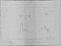
| PM03Fig. 1. British vs. Packard Merlin Performance |
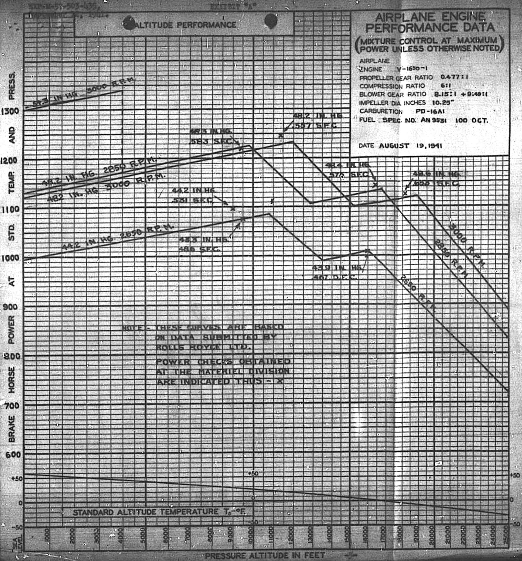
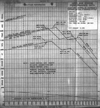
19 Aug 1941. In order to determine the ratings on which to base the V-1650-1 type test, it was necessary to first determine if the engine met the Merlin XX altitude ratings as submitted by R-R. These power checks were conducted in Dynamometer Room No. 3 in the PPL at Wright Field. Altitude conditions were simulated by controlling the carburetor inlet pressure and temperature, and by controlling the exhaust back pressure. Air flow, fuel flow, power, pressure and temperature were measured in accordance with Specification AN-9502. The mixture control was varied between automatic rich and automatic lean in an attempt to obtain best power. In most cases, best power was not obtained, but exact power checks were not necessary and would have required more engine time. The PM03Fig. 1. curve sheet compares V-1650-1 Manufacturer's No. A-4, Air Corps No. 41-46522 altitude performance with that predicted by R-R. The curves revealed that at the normal rating in low gear the engine is short on altitude by 1,700 ft. At the normal rating in high gear the engine met the predicted altitude rating. At 2,850 rpm the engine climbing speed was short by 800 ft in low gear, but made its altitude in high gear. At the 3,000 rpm military rating, the engine was short by 200 ft in low gear and 800 ft in high gear. The engine was close to the predicted altitude ratings, with the exception of the first normal rating. Further tests were necessary to completely establish the V-1650-1 altitude performance. [12 Sep 1941 Memorandum Report EXP-M-57-503-435. Altitude Power Checks of the V-1650-1 Engine, Manufacturer's No. A-4 (Air Corps No. 41-46522). P152916.] <PM03Fig01.jpg>
20 Aug 1941. Ellor, who had recently returned from a trip to England, met with Lt Col Page and Chenoweth at the Division to report on R-R developments.
Merlin. He planned to submit photographs, preliminary specifications and power curves for the Series 60 and 61 engines, and descriptive data on the differences between the Merlin 45, 46 and 47 engines. The 60 Series was for bombardment aircraft and the 61 for pursuit. Both were two-stage engines, the principal difference being that the Series 61 had a slightly lower supercharger gear ratio and a 3,000 rpm redline. The Series 60 made a 2,850 maximum rpm and developed 1,035 hp at 30,000 ft. Both had the same basic power section as the Merlin XX but were equipped with an entirely new rear section that included a two-speed gear mechanism that drove two impellers mounted on a common shaft. Unlike American two-stage engines, the carburetor was located at the first stage inlet and the fuel-air mixture was delivered to the second stage without intercooling, and then a water-cooled aftercooler before delivery to the engine. This scheme's success was entirely dependent on the effectiveness of backfire screens because of the large volume of combustible charge in the induction system. The water-cooled intercooler was supplied with a 70 – 30% water – glycol mixture and was located within the engine "V". This coolant was circulated through a small radiator adjacent to the main coolant radiator by a centrifugal pump attached to the generator adapter. Coolant circulated through a space between the two supercharger stages and the auxiliary heat exchanger, cooling the fuel-air mixture. These engines weighed 1,600 lb ±2.5% dry, without the radiator located adjacent to the coolant radiator. The control was similar to the Merlin XX and this engine series was soon to be placed in production. Ellor stated that one of the rear sections was being sent to the U.S. and believed that Don Berlin of Curtiss was anxious to obtain one for trial. MatCmd suggested calibrating an engine equipped with such a rear section on the altitude test stand at the Division.
Ellor estimated that well-designed exhaust reaction jets, maintaining substantially sea level exhaust back pressure, would give 300 thrust hp and with 250 hp being absorbed by the supercharger, they hoped to duplicate performance that would be obtained with an exhaust supercharger. However, altitudes being contemplated in England would in his estimation require both extensive geared supercharging and exhaust driven types. Efficiency of the two-stage supercharger was about 72%.
The Series 45 engine was fitted with a single-speed supercharger with a lower ratio than the high-blower gear in the Model 20; the Series 46 had a single-speed supercharger ratio equal to the Merlin XX high-blower, and the Series 47 was a Series 46 fitted with a liquid-cooled aftercooler. Ellor stated that the chief reason for the Series 47 was to raise performance with the relatively simple addition of the aftercooler.
Griffon. Ellor had brought back the latest information, which he would forward to MatCmd through the British Air Commission. Work was being done on a two-stage supercharger for this engine.
Vulture. Ellor stated that approximately 1,000 Vultures had been built and that data would be submitted through the British Air Commission. Lead-indium bearings, plus some redesign, had apparently overcome the bearing difficulties, and R-R was now working to apply Merlin cylinder blocks to the Vulture, which should have increased power to 2,600 – 2,700 bhp.
Fuel Systems. Ellor stated that it had been necessary to pressurize fuel tanks to obtain altitude performance. This was done by taking the vacuum pump output through a pressure difference regulating valve and applying a constant pressure to the fuel tanks. The British had developed two submerged fuel pumps, one having a centrifugal impeller similar to the German pump, going into the tank tops and pumping fuel out the top by the pump, which was fully submerged in the tank bottom. In addition, they had worked out a fuel system where the fuel passed through a gasoline cooler exposed to air streams, then to a vapor trap, and then to two pumps mounted on a common shaft; one supplied solid fuel and the other returned vapor from the vapor trap to the fuel tank.
Flame Damping. Blue flames were more objectionable than yellow and were more difficult to eliminate. Certain engines and exhaust stacks did a fair job of flame suppression but others were very bad. The Allison V-1710 port arrangement seemed to result in less visible flame than the Merlin.
Two-Stroke Cycle Engine. R-R was developing a 12-cylinder sleeve-valve two-stoke cycle engine (the Crecy) that was producing excellent results. It idled well and had much promise.
Whittle Engine. This engine consisted of an air compressor delivering air to a combustion chamber in which the fuel and air were burned and then delivered to an exhaust turbine and then ejected through a propulsion jet as the sole means of obtaining thrust. It had been built and flown both at sea level and at altitude at approximately 350 mph. This reaction jet replaced the propeller, but the fuel consumption was roughly 2.5 times as great as a piston engine.
Gas Turbine. R-R was engaged in developing a 3,000 hp gas turbine that would be 7' long and 4' in diameter. The propeller on this turbine would be an axial flow blower with a 4' diameter with 8 stages. R-R thought the gas turbine would be the next extensive aircraft power plant application.
Exhaust Supercharger Applied to British Engines. The British were enthusiastic about exhaust turbines and were anxious to apply it to engines that already had considerable integral geared supercharging. In particular, the Bristol Hercules 11 and Napier Sabre 118M engines were mentioned. Official arrangements were being made whereby the other two British Air Commission Members and Ellor would be designated to make contracts with MatCmd and with the General Electric Company on exhaust supercharger applications. [25 Aug 1941 Memorandum Report EXP-M-57-503-427. Conference with Mr. James E. Ellor, Rolls-Royce Representative of Packard Motor Car Company. P152551.]
4 Sep 1941. Maj E.H. White, an Air Corps Budget Officer, while processing a funding allocation covering spares for 6,000 Packard-Merlin engines, noticed that C.T.I. 182, Addendum No. I, dated 28 Mar 1941, which initiated negotiations for these spares, bore reference to "Manufacture of Certain Critical Air Corps Items, through Reconstruction Finance Corporation". Maj White believed that the subject engine spares might be purchased under a special critical material program, and requested that the LLA-3 Forms be returned and that the required funds be allotted to Wright Field from this special program. Maj White withheld signature awaiting the required funds. [Letter, Maj White to Executive, Office, Chief, Materiel Division, Washington, DC. 335.]
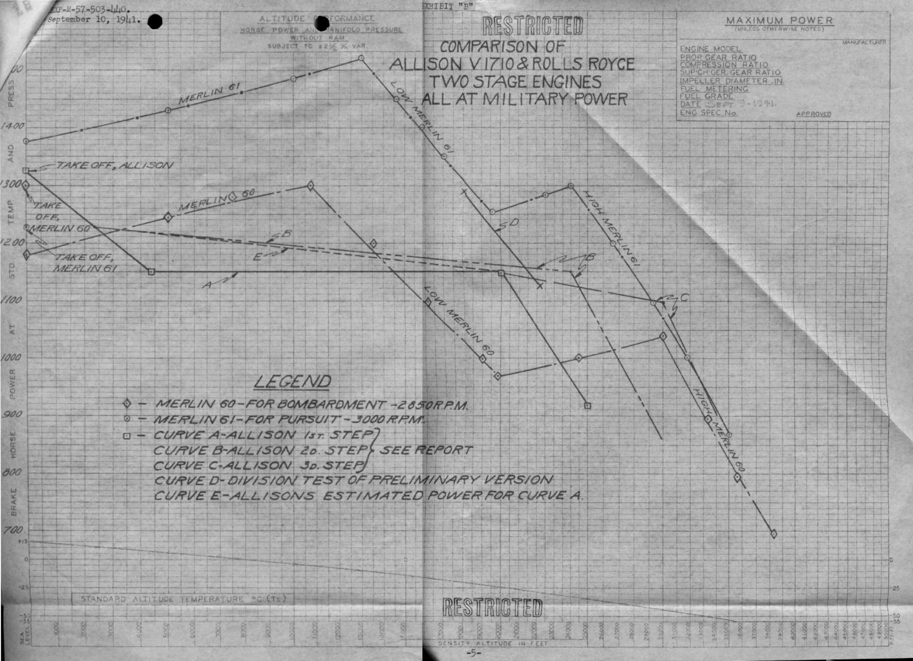
10 Sep 1941. Based on a request contained in a 16 Aug 1941 Inter-Office Memorandum ¶4-b from the Materiel Division Chief, Opie Chenoweth reported the results of a comparison between two-stage Merlin and Allison V-1710 engines. He concluded that R-R Merlin 60 and 61 engines were ahead of any two-stage engine Allison had under development because the Merlins were actually in airplanes. Allison had development under way that should equal the Merlin maximum altitude performance, but that engine was not expected to be installed in an experimental airplane for another 8.5 months. Merlin performance at altitudes below the maximum was superior, amounting to +300 bhp at 13,000 ft. Chenoweth recommended that Allison devote every effort to develop a two-stage supercharger for 1,100 bhp at 30,000 ft and the basic V-1710 engine to withstand outputs at least equal to the 1,520 bhp developed by the R-R Merlin 61 at 13,000 ft.
Background. R-R was building two versions of the two stage engine: the Merlin 60, intended for operation in bomber aircraft, had a 2,850 rpm maximum; the Merlin 61, intended for pursuit aircraft, had a 3,000 rpm maximum. The Merlin 60 had flown in a Vickers Wellington bomber and the Merlin 61 had been installed in a Supermarine Spitfire, which was due to fly about the time Ellor left England to deliver the Merlins 60 and 61 to the U.S. These engines were Merlin XX basic power sections with new superchargers and carburetors, with an adapter on the generator drive for a pump to circulate aftercooler coolant that reduced the fuel-air mixture temperature. These changes lengthened he engine by about 7". Both engines were two-speed with both impellers were on a common shaft. Fuel-air mixture leaving the carburetor passed through both supercharger stages and then to a liquid-cooled aftercooler before being delivered to the cylinders. There was a small coolant jacket, cast into the supercharger housing between the stages, that provided some cooling, but the major temperature drop was obtained by aftercooling. American two-stage engines typically placed the carburetor between the supercharger stages with only air passing through the first stage, followed by an intercooler.
Ellor submitted the following ratings, all without ram and ejector exhaust pipe advantages:
| Condition | Merlin 60 | Merlin 61 |
|---|
| Takeoff Power | 1,300 bhp at 3,000 rpm | 1,225 bhp at 3,000 rpm |
| Climb, Low Gear | 1,300 bhp at 2,850 rpm at 10,750 ft | 1,240 bhp at 2,850 rpm at 16,750 ft |
| Climb, High Gear | 1,040 bhp at 2,850 rpm at 30,000 ft | 1,090 bhp at 3,000 rpm at 29,500 ft |
| All-Out Level, Low Gear | 1,300 bhp at 2,850 rpm at 10,750 ft | 1,520 bhp at 3,000 rpm at 13,000 ft, 15 psi boost |
| All-Out Level, High Gear | 1,040 bhp at 2,850 rpm at 30,000 ft | 1,300 bhp at 3,000 rpm at 24,000 ft, 15 psi boost |
 |
| PM03Fig. 2. V-1710 vs. Merlin 60, 61 |
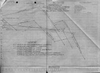
Allison had been developing a two-stage engine for several months and one had been purchased on Contract W-535-ac-16146. An experimental version had been calibrated at Wright Field to determine its critical altitude (PM03Fig. 2, Curve D). It was noted that 1,290 bhp was obtained at 18,000 ft and 1,125 bhp at 22,200 ft, using the auxiliary stage remotely driven by an extension shaft from the accessory housing and air delivered to a laboratory intercooler and then to the carburetor. Allison planned to deliver an engine for the Bell XP-39E with the following characteristics:
1) Hydraulic variable-speed coupling between the engine and auxiliary supercharger, which was located at the engine rear but was not part of the engine.
2) An auxiliary supercharger with 12.188" impeller diameter and 6.5:1 maximum gear ratio.
3) A Stromberg PT-13E carburetor installed on the auxiliary stage supercharger entrance flange but with fuel delivered to the main supercharger entrance.
4) A 7.48:1 engine supercharger gear impeller ratio.
5) No intercooler or aftercooler was to be supplied, but the 1,150 bhp at 20,000 ft shown by PM03Fig. 2 Curve A was guaranteed. Allison expected that the additional power of PM03Fig. 2 Curve E would be realized by the control method used.
As a second development step, Allison proposed to maintain 1,150 bhp to 24,000 ft by increasing the auxiliary supercharger ratio and providing a liquid-cooled aftercooler, which would be delivered as part of the engine. This engine's rating was shown by PM03Fig. 2 Curve B.
As a third development step, Allison expected to install both a liquid-cooled aftercooler and intercooler with a still higher impeller gear ratio and diffuser changes; this was expected to be available about 6 months after the second step. This engine was to develop 1,100 bhp at 30,000 ft (PM03Fig. 2 Curve C). Allison was investigating both a standard impeller of its own design and a Birmann mixed-flow impeller from the Turbo Engineering Corporation.
Engine Comparison
The engine comparison was made on the basis of maximum level flight and military power conditions since these ratings measured the engine tactical value. The power curves indicated that the Merlin two-stage engine when flying at maximum altitude-power combinations substantially equal to the performance Allison expected to obtain by 1 Jun 1942. With the many control, drive, cooler and general engine development problems Allison was likely to encounter, Chenoweth doubted the promised 1 Jun 1942 delivery.
The Allison takeoff power was 100 bhp greater than the corresponding Merlin 61 pursuit engine and 25 bhp greater than the Merlin 60 bomber engine. The 1,520 bhp delivered by the Merlin 61 at 13,000 ft was far in excess of any rating proposed by Allison and demonstrated the inherent capability of the Merlin to develop high output. This rating corresponded to a bmep of 243 psi compared to 204.5 for the Allison at its 1,325 bhp highest takeoff rating.
Weight comparison was difficult because the first Allison to be delivered was the extension shaft variety for the Bell XP-39E without either intercooler or aftercooler. When placed on the same basis of equipment and at substantially the same maximum altitude rating, it was estimated that the engine would weigh about 1,600 lb.
R-R had designed its two-stage engine so that the control would not be more complicated than a normal two-speed engine. While all the details had not been worked out, it was anticipated that Allison might have difficulty developing the variable-speed hydraulic coupling control.
Ellor explained that R-R two-stage engines must have excellent backfire screens or the engine induction system could be destroyed. Allison would be faced with similar backfire prevention issues on its second and third developments. [10 Sep 1941 Memorandum Report EXP-M-57-503-440. Comparison of Rolls-Royce and Allison V-1710 Two-Stage Supercharged Engines. 336 – 341.]
11 Sep 1941. Lt Col Carroll documented parts requiring modification in the Packard V-1650-1. During the installation of the Packard V-1650-1 on the torque stand for type test, the studs were stripped out of the generator pad and the pad for the American tachometer drive. Packard sent a new generator pad, and the tachometer drive pad was being drilled out and a through bolt replaced the stud, so these failures caused on no delay in the type test start; however, some modifications should be made to prevent recurrence of these failures. The generator drive studs had fine threads on the ends that were screwed into the aluminum mounting pads. These threads should have been course. This has been called to the attention of Packard representative Seward, who stated that Packard was already making this change.
The tachometer drive pad studs were properly threaded, but the pad was too thin to allow the studs to be inserted to the proper depth. Wright Field suggested that this was to be remedied either by building a boss on the pad so that more thread depth was obtained, or by using trough bolts in place of studs. [IOM, Lt Col F.O. Carroll, Chief, Experimental Engineering Section to Chief, Production Engineering Section, Wright Field.]
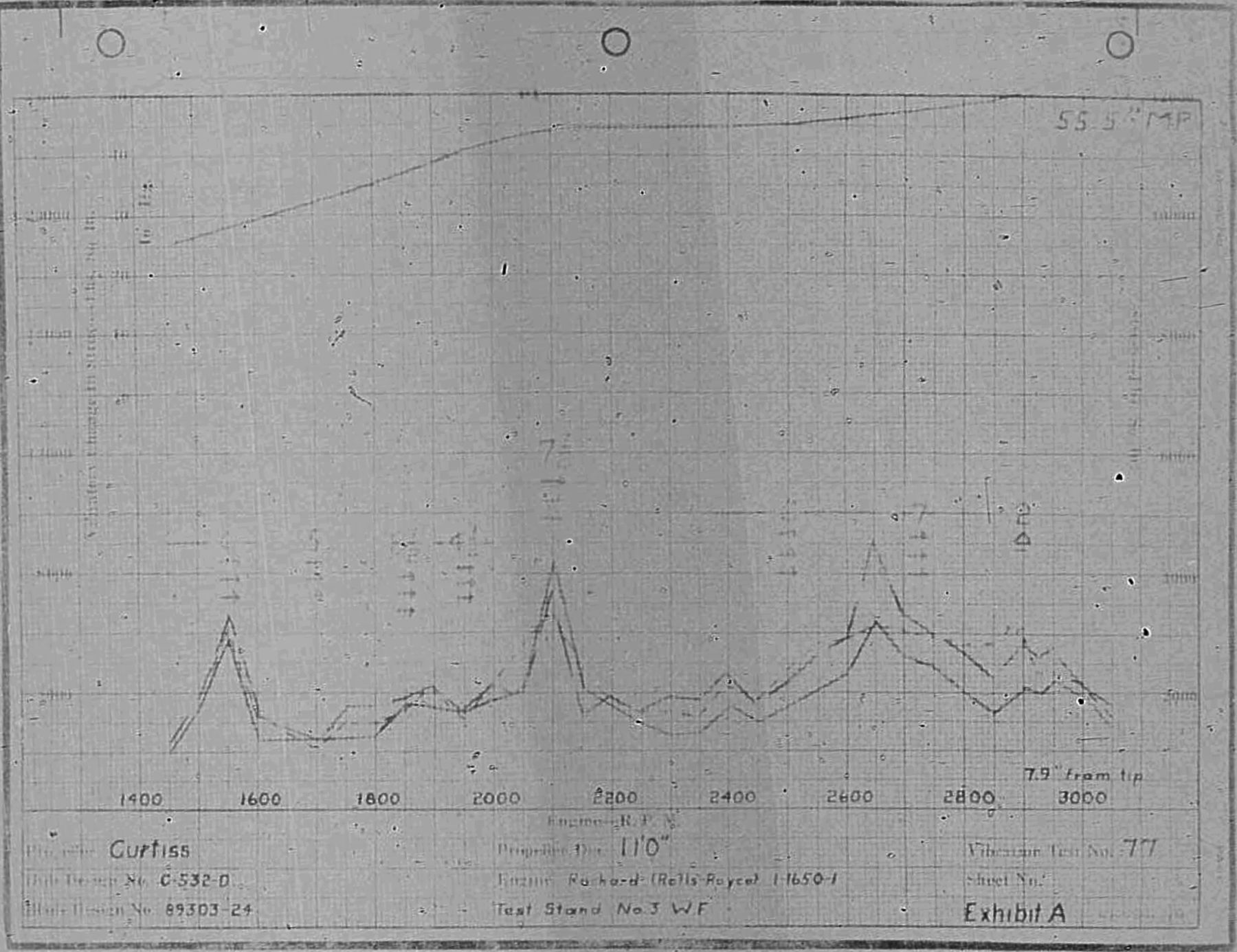
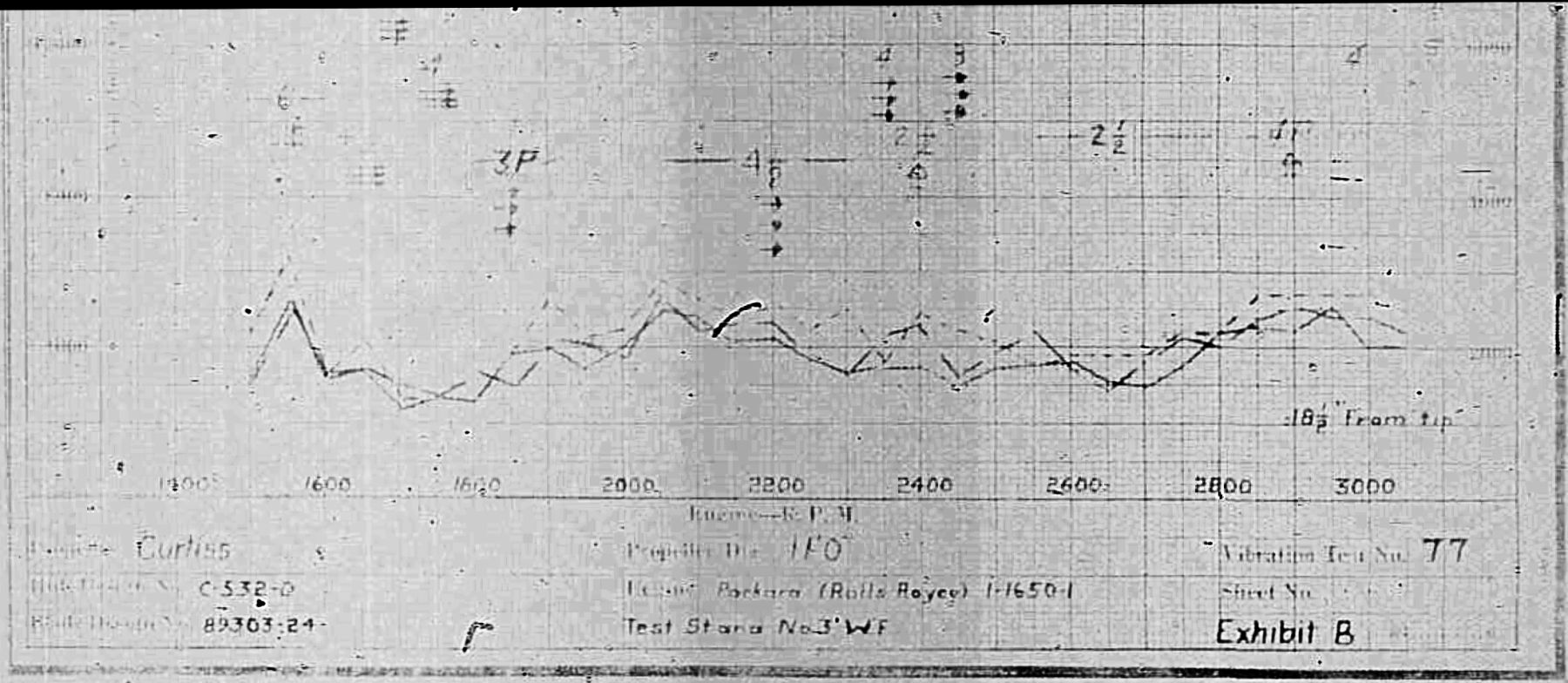
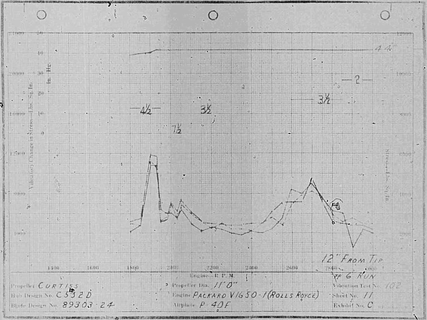
12 Sep 1941. Vibration test No. 77 was run on a Curtiss 89303-24 propeller on a Packard V-1650-1 engine as part of the propeller type test. The propeller used a Curtiss blade design 89303-24, SNs 8871, 8872 and 8873; the hub design was No. C-532-D. Engine SN AC-41-46522 was mounted on test stand No. 3 at Wright Field. The V-1650-1 had the following ratings:
| Rating | bhp | rpm | Altitude (ft) |
|---|
| Sea Level | 1,000 | 2,600 | 0 |
| Takeoff | 1,075 | 3,000 | 0 |
| Altitude | 1,035 | 2,600 | 2,250 |
| Altitude | 960 | 2,600 | 13,000 |
| Military | 1,130 | 3,000 | 5,350 |
| Military | 1,010 | 3,000 | 17750 |
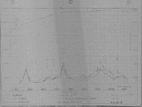
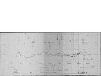
Strain gages were placed at 2.6", 5.2", 7.9", 11.9", 18.5" 27.7" 37.0" and 46.2" from a blade tip and at the 0°, 45°, 90° and 135° blade shank positions. Run were made with readings taken at every 50 rpm from 1,450 rpm to 3,050 rpm at takeoff manifold pressure, from 2,850 rpm to 3,050 rpm with constant rated bmep from 2,100 rpm to 2,850 rpm, and at full throttle from 1,450 rpm to 2,100 rpm. PM03Fig. 3A and PM03Fig. 3B show typical curves of vibratory blade stress changes, and PM03Fig. 3C sows curves of vibratory stress changes on the blade shanks. The maximum vibratory stress observed was in 6th order with values between 8,000 and 9,000 psi at a speed of 1,550 rpm at the 11.9" position and at 2,650 rpm at the 7.9" position. There was a resonance peak with values between 8,000 and 9,000 psi in 7½ order at 2,100 rpm at the 7.9" position. The vibratory changes of stress observed on the stress on the shank gages were low with a maximum value between 3,000 and 4,000 psi in several orders and at different speeds. As far as the test stand run could show, this propeller-engine combination was deemed safe for flight. [28 Oct 1941 Memorandum Report EXP-M-52-580-67-2. Vibration Survey of a Curtiss 89303-24 Propeller on V-1650-1 Engine on Test Stand. P152510.]
 |
 |
 |
| PM03Fig. 3 Curve A |
PM03Fig. 3 Curve B |
PM03Fig. 3 Curve C |
20 Sep 1941. Vincent wrote Lt Col Page to confirm decisions reached during a 17 Sep 1941 in Col Page's office, which also included Ellor and Chenoweth. Ellor explained the R-R Model 61 two-stage two-speed supercharger, including the intercooler and aftercooler, along with performance that R-R had obtained. Vincent presented a partially complete layout drawing No. PM-225 and discussed proposed changes to the two-speed drive; the changes shortened the engine by about 4", making it 3" longer than the V-1650-1; the R-R design had been 7" longer. After extensive discussion it was decided that Packard should submit a proposal covering the cost of delivering the following to the Air Corps:
(a) One set of Van Dykes of the parts list required for the two-stage two-speed supercharger as was to be shown on the finished Packard Layout Drawing No. PM-225.
(b) One set of Van Dykes of the detail and assembly drawings of parts called for in the list described in ¶(a).
(c) Two completely assembled superchargers built in accordance with the parts list described in ¶(a). One of these was to be mounted on an engine furnished by the Air Corps and put through preliminary tests before delivery.
(d) One complete set of rough castings and forgings for the corresponding parts called for in the ¶(a) parts list.
(e) One set of Van Dykes of a parts list covering the parts that would be required to replace the Packard-designed two-speed supercharger drive with a R-R two-speed drive.
(f) One set of Van Dykes of the detail and assembly drawings called for in the ¶(e) list.
(g) One set of rough castings and forgings of the corresponding parts called for in the ¶(e) parts list.
According to Vincent, the lists and parts estimates were being prepared and Packard expected to submit a proposal within a few days.
[Letter, Vincent to Lt Col Page. 344 – 345.]
20 Sep 1941. During a telephone conversation between Packard's DuBois and Materiel Division's E.A. Wolfe, DuBois furnished supplementary fuel consumption data to be used in the ongoing Packard V-1650-1 type testing. DuBois stated that if the engine were calibrated to run at specific fuel consumptions to obtain the following fuel-air ratios and air consumptions, fuel flow would correspond to the master carburetor setting and would be satisfactory for conducting the type test.
| Air Flow (lb/hr) | Fuel-Air Ratio |
|---|
| 3,000 – 6,300 | 0.076 |
| 7,000 | 0.083 |
| 7,400 | 0.0875 |
| 8,500 | 0.089 |
| ≥ 9,000 | 0. 90 |
[28 Sep 1941 Memorandum Report EXP-M-57-503-436. Fuel Consumption for Type Test Packard V-1650-1 Engine. P152915]
23 Sep 1941. PPL civilian employee W.J. Brown reported the specific fuel consumptions at which the V-1650-1 type test was to be run. No guaranteed fuel consumption data were available when the type test was started, so it was necessary to establish specific fuel consumptions from the master carburetor fuel-air ratio curves and airflow data obtained at MatCmd during the sea level calibration and from Packard.
| bhp | rpm | Blower | sfc |
|---|
| 1,300 | 3,000 | Low | 0.632 |
| 1,235 | 3,000 | Low | 0.630 |
| 909 | 2,650 | High | 0.554 |
| 1,080 | 2,650 | Low | 0.586 |
| 864 | 2,465 | Low | 0.520 |
| 756 | 2,359 | Low | 0.460 |
| 648 | 2,226 | Low | 0.450 |
| 648 | 1,855 | Low | 0.450 |
| 648 | 1,855 | High | 0.480 |
| 1,080 | 2,915 | Low | 0.626 |
These data were submitted by Packard Chief Test Engineer DuBois during his 11 Sep 1941 visit to the PPL. [23 Sep 1941 Memorandum Report EXP-M-57-503-451. Specific Fuel Consumptions Which Are to be Used for the Type Test of the V-1650-1 Engine. P152851.]
26 Sep 1941. Lt Col Carroll wrote Packard requesting that three copies of the following Packard-Built Merlin XX publications be sent to the Materiel Division:
1. Operational Instructions
2. Tuning and Maintenance
3. Installation.
4. Description.
These were to be similar to those maintained in British Air Publication 1590G, Volume I. [Letter, Lt Col Carroll to Packard. 347] Packard replied on 10 Oct 1941 that it had not completed any of the subject handbooks, but offered to send three photocopies of British Air Publication 1590G, Volume I. [Letter, Packard to Air Corps Factory Representative. 350.]
3 Oct 1941. MatCmd announced that results of tests conducted by the Division on AC-LS47-417 spark plugs indicated these had reached a point that justified the manufacturer tooling up for preliminary production. [Cross Reference No. Contract W-535-ac-15678, 348.]
14 Oct 1941. Vincent informed Lt Col Page that Ellor had received a cable advising that Merlin 61 conversion parts had been shipped. Vincent and Chenoweth suggested that the Materiel Division issue instructions through proper channels to ensure this material reached Packard at the earliest possible moment, and that upon its receipt, Packard proceed with installation on engine No. 9 and then ship the engine to Wright Field for altitude calibration, which would prove the supercharger. [Letter, Vincent to Lt Col Page. 351, 354.]
15 Oct 1941. Lt Col Page recommended that a Restricted classification be placed on the Packard Merlin two-stage two-speed engine. This purchase was covered by Authority for Purchase No. 188772, dated 14 Oct 1941, and involved American adaptation of the highest-altitude geared supercharger available at R-R, which considered it Confidential. In accordance with the corresponding American classification, this would equate to Restricted. [Letter, Lt Col Page to Lt Col Carroll. 353.]
17 Oct 1941. During preliminary tests at the Division and Packard, the AC Spark Plug Type 417-H exhibited excessive gap erosion. This had been discussed with AC, which was taking steps to modify the electrodes; all future plugs were to use these modified electrodes. Lt Carroll recommended that Production Engineering advise Packard that the AC Type 417-H spark plug was suitable for use in the Packard-Built R-R engines and should be released for preliminary production. [IOM, Lt Col Carroll to Chief, Production Engineering Section, Wright Field. 355.]
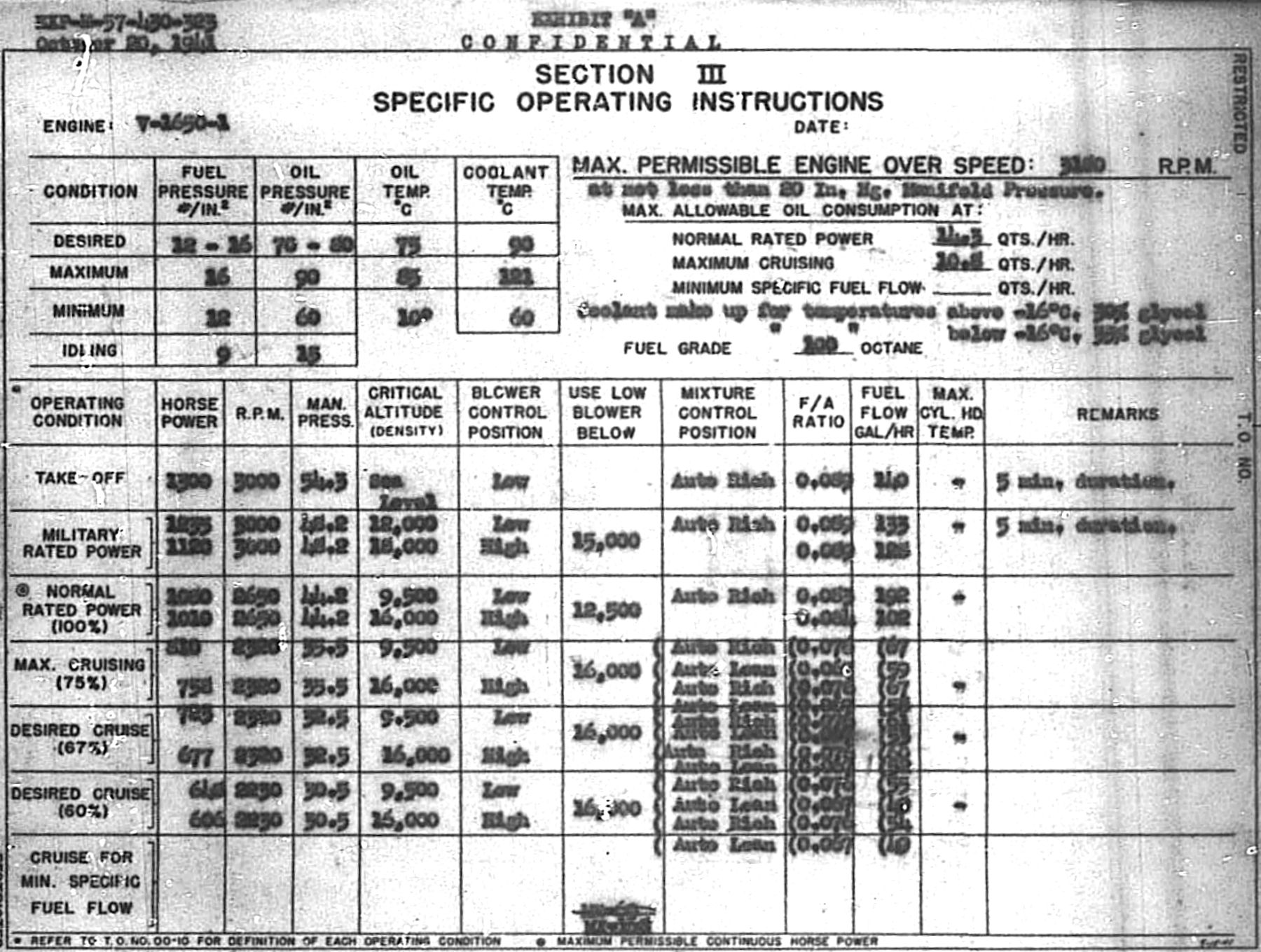
20 Oct 1941. In response to a 7 October IOM from Aircraft Projects, W.J. Brown penned operating instructions for the V-1650-1 installed in the Curtiss XP-60 airplane. These instructions were based on information obtained from the Packard booklet "Preliminary Engineering Information for Packard-Built Rolls-Royce Aircraft Engines" dated 15 Mar 1941, and curves dated 15 Feb 1941 furnished by Ellor.
Applicable Technical Orders
Technical Order 02-1-7 Detonation in Aircraft Engines
Technical order 02-1-23 Flight Operation of Aircraft Engines
Technical order 02-1-29 Ground Operation of Aircraft Engines
Technical Order 03-10G-1 Operation of Carburetor Mixture Controls
Technical Order 03-20-6 Operation of Propeller Controls During Landing
Technical Order 06-5-1 Fuels – Use and Disposition of
Technical Order 06-10-1 Aircraft Engine Lubricating Oil, Grades and Use
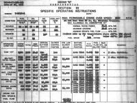 |
| PM03Fig. 4. XP-60 V-1650-1 Specific Operating Instructions |
General Operating Instructions
a. The pilot's throttle control is not conventional in that it is connected to the engine through a manifold pressure regulator (boost control) designed to prevent the rated manifold pressure from being exceeded. A gate in the control quadrant is set to limit the manifold pressure for normal operation to 48.2 inHgA, but for takeoff the control is moved through the gate to obtain 54.3 inHgA manifold pressure.
b. Starting. Start in accordance with Technical order 02-1-29 paying particular attention to the special procedures for Bendix-Stromberg injection carburetor.
c. Ground test.
(1) The engine should be ground tested in accordance Technical Order 02-1-29, except as follows: The header tank valve does not permit coolant circulation at less than 800 rpm. Therefore warming up at 600 – 800 rpm should not exceed 2 minutes at the end of which time the warm up speed should be increased to 1,300 rpm. Caution: running at reduction gear and crankshaft synchronous periods of 820, 1,135 and 1,200 rpm should be avoided.
(2) The speed loss when running on one magneto with the engine is warm and functioning properly should not exceed 100 rpm. Magneto checks should be made at 2,000 – 2,300 rpm at 30 inHgA manifold pressure.
(3) Two-speed supercharger clutches cannot be checked as outlined in Technical order 02-1-29 because of the automatic boost control. Two-speed supercharger operation should be checked by setting the propeller to "Manual" and adjusting for 2,650 rpm and 44.2 inHgA manifold pressure with the supercharger in low gear. Shift to high gear. A noticeable rpm drop should occur indicating that the high gear is engaged although the manifold pressure will remain the same.
d. Takeoff.
(1) The supercharger control must be placed in low ratio position. The constant speed governor control should be set for 3,000 rpm. The Mixture control should be moved to "Automatic Rich" position and the throttle control moved to the extreme forward position (through the gate) to give a manifold pressure of 54.3 inHgA. This takeoff throttle position overrides the automatic manifold pressure regulator and provides uncontrolled pressure of about 54.3 inHgA. Caution: This extreme throttle position should be used only until all obstructions are cleared after which the throttle must be pulled back to the gate for normal climbing speed and manifold pressure. The throttle should never be moved past the gate except for takeoff.
(2) Refer to PM03Fig. 4 for specific operating limits.
e. Flight.
(1) Refer to PM03Fig. 4 for specific operating instructions.
(2) Refer to Technical Orders for two-speed supercharger operating instructions.
f. Landing. When the engine is throttled for landing the mixture control should be set to "Auto Rich". The propeller control should be set in accordance with Technical order 03-20-6.
g. These engines are equipped with carburetors with "Idle Cut-Off" and should be stopped in accordance with Technical order 02-1-29.
h. Mixture Control
(1) These engines are equipped with Bendix-Stromberg Model PD-16-A-1 pressure type carburetors incorporating a mixture control having four main control lever settings, "Full Rich", "Automatic Rich", "Automatic Lean" and "Idle Cut-Off". Refer to Technical Order 03-10G-1 for general information and for definition of the various carburetor settings, such as "Best Power", referred to hereinafter.
(2) For operation above desired cruising manifold pressure and speed the mixture control lever shall be set in "Auto Rich".
(3) At or below desired cruising manifold pressure and speed the mixture control may be adjusted for "Best Power" or set at "Automatic Lean". When adjusting the mixture control for "Best Power", first set the propeller control on "Manual" then after the desired mixture is obtained return the propeller control to "Automatic".
i. Supercharger Gear Control
(1) This two-position control provides the pilot a choice of either the low supercharger drive gear ratio, or the high gear ratio, which produces the maximum supercharging.
(2) The supercharger control should be kept in low gear ratio for all altitudes at which the manifold pressure of approximately 44.2 inHgA can be maintained if maximum power is desired. The change to high gear should not be made as soon as the manifold pressure begins to fall after reaching full throttle. Although higher pressure will be obtained in high gear, the engine power output will be lower.
(3) Use the low supercharger gear ratio whenever the required airspeed can be obtained in this ratio to obtain maximum fuel economy.
j. Fuel and Oil
(1) The fuel grade to be used in this engine is given by PM03Fig. 4. Refer to Technical Order 06-5-1 for general information on the use and disposition of fuels.
(2) The oil grade to be used in this engine shall be Grade 1100 for all conditions. Refer to Technical Order 06-10-1 for operating temperature limits.
k. Refer to Technical Order 02-1-7 for general information and instructions pertaining to detonation in aircraft engines.
Specific Operating Limits. Refer to PM03Fig. 4. [20 Oct 1941 Memorandum Report EXP-M-57-430-323. Operating Instruction for the V-1650-1 Engine (Packard-Built Rolls-Royce Merlin XX) Installed in the Curtiss XP-60 Airplane. P141691.]
21 Oct 1941. Lt Col Carroll announced that Packard Merlin engines were being delivered to airplane contractors for installation. Packard had submitted a dimensioned sketch of a Packard Merlin installed on a Packard overhaul stand. Examination of the sketch and Drawing 40K9311 revealed that adapter plates could be designed that would make it possible to use the Air Corps inline overhaul stand for the Packard V-1650-1. Drawings for this adapter plate had been started, but would probably not be complete before mid-December. The PPL had retained Packard's drawing 40K3911 for use in designing the adapter plates. [IOM, Lt Col Carroll. 357.]
28 Oct 1941. Cross Reference Nos. 452.8 V-1650-1 Packard and 542.025 Curtiss 89303-24 Propeller commented that the 28 Oct 1941 Memorandum Report EXP-M-52-580-67-2, Vibration Survey of a Curtiss 89303-24 Propeller on V-1650-1 Engine on Test Stand, Vibration Test #77 made on 12 Sep 1941, was part of the propeller type test. The propeller-engine combination was judged safe for flight. [Cross Reference No. 452.8 V-1650-1 Packard. 359.]
12 Aug 1941 – 1 Nov 1941. A successful V-1650-1 type test was run on a Packard Merlin V-1650-1. Changes in design would be necessary to make those parts found defective satisfactory for service. A Model Test would be necessary to prove the deficiencies had been eliminated. The test was conducted in accordance with Specification AN-9502a, dated 30 Mar 1940, at the following ratings, which were based on those the British used for the R-R Merlin XX, and a check made before the test on the critical altitudes:
1,080 bhp at 2,650 rpm at 9,500 ft – normal critical altitude, low ratio
1,010 bhp at 2,650 rpm at 16,000 ft – normal critical altitude, high ratio
1,235 bhp at 3,000 rpm at 11,700 ft – military critical altitude, low ratio
1,120 bhp at 3,000 rpm at 18,300 ft – military critical altitude, high ratio
1,300 bhp at 3,000 rpm at sea level – takeoff for 5 minutes
3,180 rpm rated overspeed dive for 20 seconds
The engine was given a 20-hr penalty run in addition to the 150-hr type test, necessitated by the installation of the following new parts after 20 hrs had been completed: boost control reduction gears and bellows, larger camshaft driving gear bolts on both A and B banks. At the end of the 150-hr type test the engine was completely disassembled except for the reduction gear assembly and a thorough inspection made. The following parts were found in an unsatisfactory condition:
a. Three pistons were cracked in the fillet between the piston pin boss and skirt.
b. The chromium plating on 13 rocker arm follower pads had cracked or chipped off.
c. The front flame trap framework had cracked in the corners.
d. The impeller shaft had been grooved by the front supercharger bearing inner race and as a result the spacer on the impeller shaft had worn enough to allow the impeller to scrape the supercharger case.
e. The copper rivets in the both supercharger drive high clutches had sheared off.
f. The main supercharger drive spline coupling had cracked parallel to the coarse spines and diagonally across the fine splines.
When the 20-hr penalty run ended the reduction gear and camshaft driving gear bolts were inspected and in satisfactory condition; and the boost control aneroid had failed. [6 Nov 1941 Memorandum Report EXP-M-57-503-478, Type Test of the V-1650-1 Engine, Manufacturers No. A-4, A.C. No. 41-46522. 364 – 365.]
4 Dec 1941. Ellor reported that the Merlin 61 supercharger parts had been at Packard for the past few days and were being installed on an engine. [Telephone, Telegram P-228, PPL to Experimental Engineering. 370.]
5 Dec 1941. Curtiss advised that a cylinder head gasket on the left bank #2 cylinder had blown. Engine serial number was 41-46524 was removed from the Curtiss XP-40F airplane and Curtiss requested expedited disposition on a replacement or repair. [Telegram. Lt Col K.B. Wolfe to Packard. 372.]
 |
 |
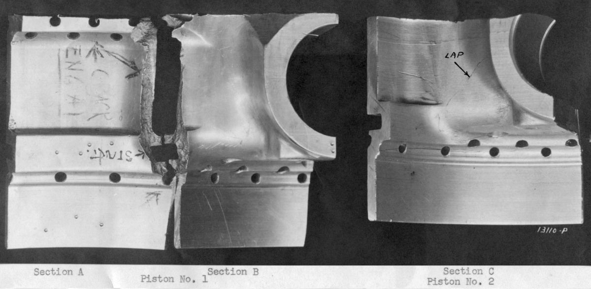
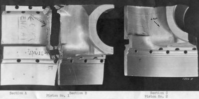
PM03Fig. 5. Piston Sections from R-R A-1 Engine.
Piston No. 1 = Failed Piston; Piston No. 2 = Stock Piston. |
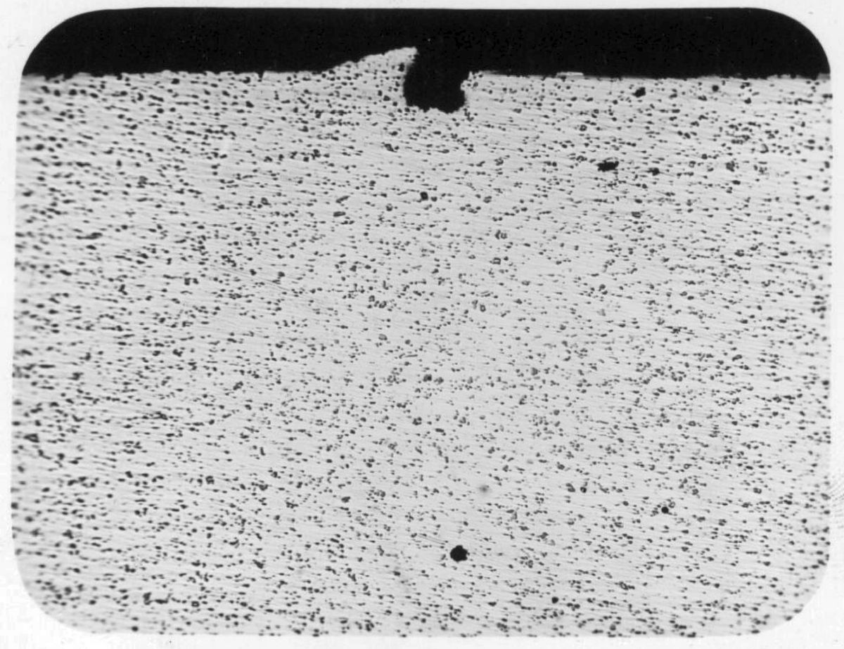
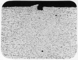
PM03Fig. 6. Magnification = 100x
Etch = None. Showing Notched Forging Lap in Piston from R-R A-1 Engine Stock. |
9 Dec 1941. Packard submitted three piston sections forged from 18S aluminum alloy. PM03Fig. 5 Section C was a section from stock that exhibited a forging lap. Sections A and B were from a piston that failed during test. The fracture appears to have resulted from a fatigue failure that had its nucleus at the point marked "Start". Macro-etching Sections A and B did not reveal forging laps; however since the piston fracture may have occurred along the lap, a lap may have been present in the piston before failure. The micro-examination did reveal evidence of a lap during the forging operation in Section C. Section A, B and C microstructure examination proved them similar and normal in microcharacter. PM03Fig. 6 shows a photomicrograph of the lap present in a stock piston's Section C. Such a notch, as was visible in PM03Fig. 6, was a defect that might serve as a nucleus or fatigue failure starting point. Hardness explorations of areas cut from all three sections proved that piston 1, sections A and B, were softer. Hardness results are as follows:
| Location and Condition | Piston No. 1 Failed During Test (BHN*) | Piston No. 2 Stock Piston (BHN) |
|---|
| Boss Section as Received | 68 – 75 | 124 – 132 |
Boss Section Heated
24 hrs at 300°F | 70 – 80 | 130 |
| Skirt Section as Received | 65 – 75 | 110 – 126 |
Skirt Section Heated
24 hrs at 400°F | 64 – 75 | 107 - 116 |
| *BHN = Brinell Hardness Number |
Conclusions. The hardness tests indicated that the piston skirt had become unusually soft after operation. This was induced by high operating temperatures inside the test engine. Since the soft piston did not harden upon being held for 24 hrs at 300°F and 400°F, the softness was not caused by improper heat treatment, but by heat conditions in the engine. The piston failure appeared to have resulted from a combination of defects, namely the forging lap and softening in an over-stressed piston section. MatCmd recommended the piston be redesigned to withstand more stress in sections near the pin boss. Steps were to be taken to prevent forging laps and excessive heating within the engine. [9 Dec 1941 Memorandum Report EXP-M-56-3956. Piston, Rolls-Royce A-1 Engine. 374 – 377.]
15 Dec 1941. Maj James. H Doolittle, working as the Automotive Liaison Officer, Air Corps Office of the District Supervisor in Detroit, Michigan, wrote Col Echols with news that Packard had two completed Merlin engines boxed and ready for shipment to Canada. Due to a 9 December telegram, issued by the Central Procurement District, all contractors were to have stopped shipments on Defense Aid Contracts. These Merlin engines were peculiarly built and adapted for installation in British airplanes only and were not useful in American aircraft. Maj Doolittle requested clarification of this recent ruling to be expedited so that the British engines could be shipped immediately. If the ratio of British to American engines produced at Packard was to be changed to favor American engine, instructions to that effect would have to be issued as there were more British engines in the mix than American. [Letter, Maj Doolittle to Col Echols. 378.]
15 Dec 1941. The Experimental Engineering Section cabled the PPL Engineering Section Chief regarding Curtiss Electric propellers that were to be in stalled on Canadian-built Hawker Hurricanes with Packard Merlin XXVIII engines. The propellers operated on 24 volts while the airplane required 12 volts. The most practical solution was to rewind the propeller motors to operate on 12 volts. The writer suggested that if the propellers had already been delivered that the motor assemblies, relays and circuit breakers be returned to Curtiss for conversion. Curtiss Propeller Division had confirmed this was permissible and would not interrupt production schedules if the delivery rate was spaced over a reasonable time period. It was not deemed practicable to obtain 24 volts for the propeller by adding a motor generator because of added weight, wiring complications, addition battery drain, and probable unsatisfactory propeller operation. Maximum current draw was about 20 A and average was 3 A for 24 V operation. If this method were contemplated it was preferable to install an independent 24 V propeller electrical system, including generator, battery, etc. This method was deemed impractical versus converting the propeller to run on 12 V. [Telegram EXP-T-4, Experimental Engineering to PPL. 379.]
18 Dec 1941. Packard Test Engineer R.N. DuBois wrote Willis J. Brown in the PPL covering three prints of Drawing PME-5682, a carburetor flange to be used in the Merlin 61 conversion, which was being prepared for shipment to Wright Field. The Merlin 61 installation drawing had no flange detail. The general engine installation was shown in R-R drawing D-16968, which was included in "Preliminary Specifications for Rolls-Royce Merlin 61 Engine", then in possession of the Materiel Division. [Letter, DuBois to PPL. 380.]
18 Dec 1941. The trouble experienced with the ball bearing on the supercharger shaft was traced to high supercharger section temperature. Running of the Packard SN A-9 engine equipped with the Merlin 61 supercharger was to be minimized and the engine was to be returned to Packard, where new parts would be installed before it was installed in an airplane. [Cross Reference 452.9 Supercharger, Rolls-Royce. 381.]
18 Dec 1941. Packard Chief Test Engineer R.N. DuBois wrote Lt Col Howard H. Couch, Chief, Propeller Laboratory confirming his request made through Lt Col Page during his 11 December visit to the PPL. Packard had requested the loan of an 11' Curtiss electric propeller, design No. 89303-24, hub design No. C 532 W, along with complete control equipment, governor, etc. This was the same propeller design that had been used for the V-1650-1 type test and Packard required its use during model testing and carburetor calibrations for the Air Corps. [Letter, DuBois to Lt Col Couch. 382.]
20 Dec 1941. Lt Col K.B. Wolfe of the Production Engineering Section cabled the Materiel Division Chief, asking whether the 3,000 Packard V-1650-1 engines were to be released to the British. If so, Packard was to be notified so that material and manufacturing capacity could be scheduled. [Teletype Prod-T-693. Lt Col Wolfe to Materiel Division. 383.] The Technical Executive responded on 23 Dec 1941 stating that the plan was to release 1,227 British engines, but that the plan was tabled by the Joint Aircraft Committee pending discussion of a General Joint Defense Program. [Telegram E-868. Executive to Technical Executive. 385.] On 24 Dec 1941, Lt Col Wolfe wrote the Air Corps Central Procurement District Supervisor stating that it was satisfactory for Packard to continue shipments of British engines and spare parts as produced. [Letter, Lt Col Wolfe to District Supervisor. 387.]
22 Dec 1941. In a conference at the Division attended by Ellor representing the British Purchasing Commission, DuBois of Packard, and Wolfe, Brown and Rodemuller of the Division.
1. The attendees decided that V-1650-3 engine test procedures would include the following checks:
(a) Critical altitude at both 60.5 inHgA and 48.2 inHgA manifold pressure at 3,000 rpm in the high speed supercharger gear.
(b) Critical altitude at 60.5 inHgA at 3,000 rpm in the low speed supercharger gear.
(c) The effect of manifold temperature at the critical altitudes of the high speed supercharger gear at 3,000 rpm.
(d) The manifold pressure required to deliver 1,300 bhp at 3,000 rpm in low supercharger gear at sea level.
(e) Output at 48.2 inHgA manifold pressure at 2,650, 2,850, and 3,000 rpm in low supercharger gear at sea level.
2. It was further decided that heat rejection data should be obtained if possible at the maximum power rating.
3. The method given by Ellor for computing the temperature rise when using an aftercooler was as follows:
The temperature rise from air inlet at carburetor to induction pipe in °C was:
4t = (1 - x) * ((0.88 vm²) / 104)
Where x was the proportion of heat taken out by jacket cooling of the supercharger casing and the aftercooler.
Vm = (V1² + V2²)0.5
Impeller1 diameter = 11.5"
Impeller2 diameter = 10.1"
Low Gear Ratio = 6.39:1
High Gear Ratio = 8.03:1
In Low Gear
V1 = 0.3205N
V2 = 0.2815N
In High Gear
V1 = 0.4027N
V2 = 0.3540N
N = Crankshaft Speed in rpm
4. Engine running time at the factory was 3 hrs 14 min.
[27 Dec 1941 Memorandum Report EXP-M-57-503-512. Conference on the Operation and Test Procedure to be used on the V-1650-3 Engine (Merlin LXI). P153109.]
23 Dec 1941. Packard Chief Test Engineer DuBois wrote Willis J. Brown of the PPL transmitting Report No. 3298-3, Delco Appliance Division "Report on Investigation of Aneroid for Boost Control Serial No. 20," and report No, RR-42, "Breaking of Spline – Spring Drive Main Drive Shaft Driving" to the Division. [Letter, DuBois to Brown. 386.]