Armstrong Siddeley Panther IIA
Part 2: Auxiliary Section
Compiled by Kimble D. McCutcheon
Published 20 Dec 2024
| Part 1: Power Section |
| Part 2: Auxiliary Section |
| Part 3: Induction, Ignition and Lubrication |
Part 2: Auxiliary Section
Fan and Fan Drive
 |
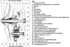
| Fig. 20. Fan and Drive |
The fan was mounted at the rear of a spindle that was supported at its center in the fan induction casing, and at its front in the crankshaft rear end. The fan was driven at 3.82 times crankshaft speed through an intermediate compound gear wheel behind the rear diaphragm, which was in turn driven from the smaller diameter portion of the gear at the crankshaft rear end. The intermediate gear contained a centrifugally-loaded friction clutch by which the fan was insulated from the effects of harsh and sudden torsional vibration in the drive from the crankshaft. The components concerned, therefore, in the fan and drive were the fan intermediate gear and spindle, and the fan and spindle, are illustrated in Figure 20.
The intermediate gear consisted of a pinion (17), which was meshed with the crankshaft gear (10), a set of six clutch pacts (16) that were dogged to the pinion, a large gear (23) that was driven by the clutch pads and meshed with a gear (12) on the fan spindle (13), also a mounting sleeve (21), a ball bearing (24) and a roller bearing (20). The pinion (17) was hollow and was mounted freely on the boss of the gear (23) where it was located between a shoulder around the boss and a flange at the front end of the of the gear (23) when the pads were flung outwards under centrifugal force. The mounting sleeve (21) was flanged at the front end and was inserted through the front end of the boss of the gear wheel in which it was retained by a nut (25), screwed and secured by a split taper pin to its rear end. The sleeve bore front end was ground to provide the outer race of a roller bearing on which the front end of the gear was supported. The rear end of the gear was supported on a ball bearing (24) whose outer race was located immediately beneath the teeth of the gear, being secured between a shoulder and a spring ring in the sleeve bore
The spindle (19) for the fan intermediate gear was hollow, and was drawn up into a boss at the back of the rear diaphragm by a nut (18) screwed to its front end. The inner race (20) of the roller bearing was mounted on the spindle against a shoulder; the nut, mentioned above, dres up to the end of the boss on the diaphragm. Separated from this race by a tubular spacer (22) was the ball bearing inner race; this race, the tubular spacer and the roller bearing inner race of the were secured by a nut (26) screwed to the spindle and locked with a tab washer. Various oil grooves and transfer holes were provided in the mounting sleeve, gear and pinion.
The fan (4) was machined from an aluminium alloy casting and was mounted, not directly upon the fan spindle (13), but upon a component (5) known as the fan carrier. The fan carrier was a steel sleeve, serrated at the rear end for engagement in the boss of the fan and formed near the front end with a flange. The flange rear face provided the abutment for the fan boss, and the front face for four coil springs (6). The springs forced a phosphor bronze gland ring (7) mounted on the sleeve front end and dowelled to the flange up against the fan spindle rear bearing housing. The carrier was keyed to the fan spindle and retained by a nut (2), which also secured the fan on the carrier. The fan spindle was hollow and had the inner race of a small ball bearing (14) retained by a nut (15) against a shoulder at the front end. A spur gear (12) that engaged the fan intermediate gear was keyed to the spindle near the center, and was retained against a shoulder by the rear bearing inner race (9) and an oil thrower washer (8), against which thefan carrier front end was pressed. The nuts at the front and rear ends of the spindle were locked with split taper pins, and a large fairing cap (1) was screwed to the fan boss to screen the rear nut.
Auxiliary Drive Shaft and Drive
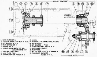 |
| Fig. 21. Auxiliary Shaft and Idler Wheel |
The auxiliary drive shaft was carried in the induction casing and induction casing cover above the crankshaft to drive the magnetos, gun gear, etc., and to transmit the drive from the hand turning gear to the crankshaft. The shaft was driven through a separately-borne spur gear into which its front end was splined, and transmitted the drive to the magnetos and other auxiliaries through a bevel gear and a spur gear near its rear end; a claw integral with the shaft rear end received the drive from the hand turning gear. The shaft was supported at the rear end in a ball bearing in the induction casing cover, and at the front end in the gear. The gear received the drive from the larger crankshaft gear through an idler gear carried at the back of the rear diaphragm. The following components were concerned with the auxiliary drive shaft and its drive: idler gear and spindle, driving gear and auxiliary drive shaft.
The idler wheel (16) was hollow and formed at the front end of a hollow boss. The bores of both boss and wheel were ground to form the outer races of rings of uncaged rollers which bore directly around the idler wheel spindle (15). The wheel was located axially upon the rollers by shoulders on each side of the rear race; no such shoulders were provided around the front race. The idler wheel spindle was hollow and was drawn up into a boss on the rear diaphragm by a nut (17) at its front end. The inner race for the front ring of rollers was formed as a channel-sectioned track around a broad shoulder upon the spindle, which was drawn up to the boss on the rear diaphragm. The inner race for the rear ring of rollers was an L-sectioned track around a second shoulder towards the spindle rear end. The rollers were located around the rear race by a flange around the sleeve front end (14) mounted on the spindle to the rear of the shoulder and retained by a nut (13). This sleeve retained the idler gear as a whole upon the spindle.
The auxiliary drive shaft driving wheel was formed at the front end of an internally splined sleeve (12), the exterior of which was ground to provide the inner races of two rows of uncaged rollers. The rollers were separated by a tubular spacer (10) around the center of the sleeve and were retained by a nut (9) screwed to the rear end of the sleeve and secured by a lock plate (8). The lock plate was splined to the sleeve end and secured to the nut by three screws. The outer races for the rollers were ground in the front and rear ends of a second sleeve (11). This sleeve was flanged at the front end for retention in the induction casing, and has shoulders in the bore to effect the axial location of the rollers.
The auxiliary drive shaft (7) was a solid shaft having at its rear end a ratchet claw that engaged the hand turning gear. The ball bearing inner race (4) in which the shaft rear end was supported was mounted immediately in front of the claw. The race was retained against the front of the claw by an internally splined sleeve (6), which was a push fit over splines around the shaft and was secured on the shaft with a circlip. The bearing outer race was mounted in a steel housing (5) secured by a flange around its rear end to the diaphragm in the back of the drive housing in the induction casing. A ring nut (3) secured by a lock plate (1) retained the outer bearing race against an internal lip at the front end of the housing. 'The sleeve (6) had near its center a ring of spur gear teeth to transmit the drive to the gas starter distributor and other auxiliaries, and at its front end a ring of bevel gear teeth to drive the magneto layshafts. The front end of the shaft, which was also splined, was a slide fit in the splined bore of the auxiliary drive shaft driving wheel.
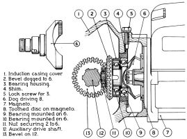 |
| Fig. 22. Magneto Layshaft |
The layshaft (6) of Figure 22, through which each magneto was driven, had a bevel gear (2) mounted on and dogged to its inner end. The jaws at the spindle end were internally serrated. The bevel gear meshed with the bevel gear (13) on the auxiliary drive shaft (12), and the jaws engaged a disc (8) keyed to the magneto spindle. The spindle was supported in two ball bearings (9) and (10), of which the inner races, separated by a spacer, were retained on the spindle by the back of the bevel wheel (2). The outer bearing races were freely mounted on each side of a central shoulder in a steel housing (3). The housing was screwed into the side of the induction casing drive housing, where it was locked by a set screw (5). Adjustments for depth of mesh between the layshaft and auxiliary drive shaft bevels was provided by a shim (4) fitted between the end of the bearing housing socket and a flange around the outer end of the bearing housing. A minimum timing adjustment of 12° was effected by altering the meshing of the layshaft with the disc keyed to the magneto spindle by one tooth.
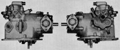 |
| Fig. 23. Auxiliary Drive Unit |
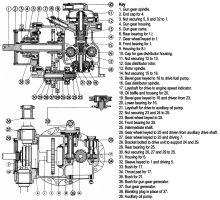
The casing was in three parts – the body, the distributor cover and the gun gear housing. The body was divided internally into front and rear compartments The rear compartment housed the front end of the gun gear spindle and the front bearing for that component; its rear end received the gun gear housing. A bracket supporting the intermediate shaft was retained beneath the rear compartment by two studs. The front compartment was fitted at its upper and lower ends respectively with a bush and bearing housing for the gas distributor spindle. Bushes for the reception of the auxiliary oil pump and engine speed indicator layshafts were fitted in the port side of the front compartment. A facing to which the fuel pump was attached was provided on the starboard side of the front compartment. The upper end of the front compartment projected above the main body of the casing, and in it an annular track for the gas distributor rotor was machined. Each of the fourteen equally spaced ports around the track communicated via a duct with a socket for a hollow stud in the side of the casing. The studs, when the distributor was in use, receive banjo unions at the ends of pipes taken to the cylinder non-return valves; when delivered to the Service, the hollow studs were fitted with blanking sleeves, as the distributor was not used. A flange for the attachment of the distributor cover projected beyond the distributor track. A union and an oil priming nipple were mounted in the casing at the back of the distributor track. The union supplied oil to the bush that supported the distributor spindle upper end. The distributor cover was a flanged cup secured by five studs to the flange around the distributor track. A union for the connection of a pipe from the source of starting mixture was fitted horizontally across the top of the cover.
The cylindrical gun gear housing was attached to the auxiliary drive unit body by a flange around its front. A shoulder in the gun gear housing front received a steel housing for the driving spindle rear bearing. The gun gear housing rear end was internally threaded to take a duralumin cover through which the gun gear spindle end projected. A flanged sleeve for mounting a gun gear generator was secured by two studs to a facing around an aperture in each side of the gun gear housing. When no gun gear was carried, the sleeves were blanked off by hollow shouldered plugs fitted at the outer ends with ring nuts.
 |
| Fig 24. Auxiliary Drive Unit |
The intermediate shaft (see fig. 24) consisted of a spindle (25) having large and small spur gears (26) and (27) keyed side by side at its center, and a small bevel gear (23) at its front end. The larger gear engaged the auxiliary drive shaft, the smaller gear drove the gun gear spindle, and the bevel gear operated the gas distributor spindle (16). The spindle was supported in two ball bearings (24) and (29), carried in the bracket (28) fitted beneath the drive casing. The rear bearing inner race was mounted directly upon the spindle behind the smaller gear, where it was retained by a nut (30) that bound it and the two gears against a shoulder near the spindle front. The front bearing inner race was mounted around the boss of the bevel gear (23), which was keyed to the spindle in front of the shoulder against which it was retained by a nut (22). Lips were formed at the bearing housing inner ends in the bracket to limit the end float of the gear.
The gun gear spindle (1) was driven at airscrew speed through a spur gear (7) keyed close to its front end. The gear was a push fit on the spindle and abutted a shoulder thereon, but was not otherwise positioned. A ball bearing inner race (8) was mounted on the spindle in front of the gear but, apart from abutting the gear boss, was not positioned. A second ball bearing inner race (6) was mounted on a flanged sleeve (32), keyed to the spindle behind a shoulder near the spindle center, and was positioned between the shoulder and the sleeve flange. The flange rear face bore a radially-serrated lip, which engaged a similar lip on the front of a two-lobed cam freely mounted on the spindle behind it. The cam had a similar lip on its rear face for engagement of a second and similar cam fitted to the spindle behind it. The two cams (5) and the flanged sleeve (32) were held up to the shoulder around the spindle by a nut (3). The spindle projected through the gun gear housing end cap (2) to the rear of the nut, and was provided with a helical oil retaining groove to prevent oil leakage at that point. Shaft end float was limited by the outer bearing races, the front race being prevented from moving forwards by a lip at the front end of its housing, and the rear race being prevented from moving rearwards by a shoulder to the rear of its housing.
The gas distributor spindle was carried vertically in the drive unit body front compartment, and was driven at half crankshaft speed through a bevel gear (19) keyed and nutted to its lower end. The spindle was not attached directly to the rotor, but received a spindle (13) on which the latter was mounted in its upper end; a cotter or peg passed through both components and transmitted the drive from one to the other. A bevel gear (15) keyed to the spindle near its center and retained by a nut against a shoulder thereon, drove the fuel pump, which was attached to the starboard body side. A skew gear (16) was formed around the spindle a short distance below the bevel gear to drive the engine speed indicator and auxiliary oil pump layshafts. The spindle incorporated elaborate oil grooves at the upper end, where it was supported in a bush pressed into the drive casing; it was supported at the lower end in a ball bearing (20). The inner race of this bearing was mounted upon the boss of the lower bevel wheel (19), and was gripped between shoulders around the boss and the spindle. The outer race of the bearing was located positively between a shoulder and a spring ring in the bore of an aluminium housing (18) carried in the body of the drive unit. The housing included a tubular extension that projected into the front compartment interior so that a small quantity of oil was retained therein.
The rotor (12) was a phosphor-bronze disc having a short peripheral transfer port through which the compressed mixture supplied to the distributor cover reached the ports in the distributor track. A taper-bored boss was formed at the upper face of the rotor for its attachment by a nut (11) to the upper end of the rotor spindle (13). The rotor spindle was a short spindle, the lower end of which was received in and cottered to the upper end of the distributor spindle. Except when the distributor was in operation, the rotor was maintained clear of the track by a coil spring fitted between the rotor spindle lower end and the distributor spindle bore bottom. The cotter slot in the rotor spindle was deeper than the cotter, and permitted the rotor to be blown down on to the track in the drive casing when compressed mixture was delivered to the distributor cover. The rotor was adjusted and locked so that mixture commenced to be delivered to each cylinder after its piston has passed 12° beyond TDC firing stroke, and the delivery was discontinued about 30° of crankshaft movement later. The rotor spindle axial and radial drilling permitted the spindle to be used with a rotor by which the cylinders on induction stroke could be supplied with mixture; this rotor was not supplied for Service use.
The auxiliary oil pump (17) and engine speed indicator (21) layshafts were carried in flanged bushes (33) and (35) respectively in the auxiliary drive casing port side, and were driven at one quarter engine speed through skew gears integral with their inner ends. The oil pump layshaft (21) was the longer of the two, was hollow and had the outer end slotted to drive the pump. The engine speed indicator layshaft (17) was hollow and had the bore center portion squared to engage the squared end of the flexible shaft to the indicator. The skew gear reaction of each shaft drew the shaft inwards against a phosphor-bronze in the drive casing starboard side. The oil pump layshaft bush flanged end, in addition to retaining the bush in place, provided mounting for the auxiliary oil pump. A screwed union for the sheath of the flexible shaft to the indicator was machined on the retaining flange of the bush for the indicator layshaft.
 |
| Fig. 25. Fuel Pump |
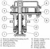
The fuel pump (Fig. 25) was driven at half crankshaft speed from the bevel gear at the gas distributor spindle center and was of the meshed pinion type. The pump was retained as a unit to the auxiliary drive unit starboard side by a flange around one of three castings, which comprised the pump body. Of these three castings, the one (3) attached to the drive unit was of aluminium, and consisted of a housing for two packing glands and a chamber from which oil and fuel leaking past those glands was drained via an external pipe to the induction elbow. The housings for the glands were formed at the outer end of the drainage chamber, and in the outer end of a bronze bearing (1) for the inner end of the driving spindle (11). This bearing was received in the inner end of the drainage chamber, where it was retained by four studs. The gland packings were of cork compressed into the gland housings by duralumin washers borne on by a common spring (10) fitted around the driving spindle between the two housings. The central body casting (7), also of aluminium), was the pump casing proper and was open-ended; a phosphor-bronze end plate (4) was fitted between this casting and a shaped facing at the outer end of the gland housing. The third body casting (6), which was of phosphor-bronze, formed the outer cover for the outer end of the pump casing, and provided a stub axle for the driven pinion (8); the inlet and outlet unions for the pump were mounted in this casting. Eight common bolts secured the three portions of the pump body together. The driving pinion (5) was keyed to the outer end of the spindle (11) at the inner end of which the driving bevel was machined. The spindle was supported in the bearing carried at the inner end of the gland housing, in the outer end of the gland housing and in the pump casing cover. No provision was made for lubricating the two latter bearings.
The auxiliary oil pump ((39) of Fig. 24), was a small reciprocating plunger pump driven at one-quarter engine speed from the pump layshaft in the auxiliary drive unit. All pump working parts were housed in a single casing provided with a flange for its attachment to the drive unit. The casing housed a bush that supported a spindle tongued at the outer end for engagement with the slotted end of the layshaft. The further end of the spindle was provided with an eccentrically located pin fitted with a bush to engage a slot in the side of the plunger. The plunger worked in a barrel at right angles to the spindle housing. As the spindle was turned, the plunger was forced to travel backwards and forwards in the barrel. The ends of the barrel were provided with unions for the inlet and delivery oil pipes, and were fitted with unloaded non-return ball valves. A spring-loaded transfer ball valve was fitted in the head of the plunger, and through it oil drawn into the intake end of the barrel, by the out stroke of the plunger, was transferred to the delivery end on the back stroke of the plunger.
 |
 |
 |
| Fig. 26 | Fig. 27 | Fig. 28 |
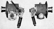
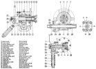
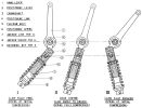
Figures 26-28 illustrate the hand turning gear; the annotations in the text refer to those in Figure 27.
The gear casing consists of a cylindrical body (12) closed at the front end, and open at the rear, and a cover (2) spigoted and studded to the body rear end. A spigot and flange around the front body end provided for the location and attachment of the casing to the induction casing cover. An L-section outer race (7) for a ball bearing that supported the worm wheel shaft front end was housed centrally in the casing front end, and a similar sectioned race (3) for a roller bearing that supported the shaft rear end was carried in the cover. A bush (27) and a bearing plate (25) were fitted to the body starboard and port sides to support the worm shaft that was carried beneath the worm wheel. The bush was retained by a shoulder around its inner end being drawn up to the inner end of its housing by a cap (28) screwed to its outer end; when it was desired to operate the worm shaft starboard end, the cap could be replaced by a nut. The bearing plate was retained by four studs and carried two spring-loaded pawls (23) that engaged a ratchet fitted to the worm shaft. In addition to sealing the body casting end and supporting the worm wheel shaft, the end cover provided the mounting for the turning claw striking gear. The casing lower portion acts as an oil reservoir for worm and worm wheel lubrication, and was filled through a nipple in the upper portion.
The worm wheel carrier (4) was hollow, and was splined internally at the rear end to transmit the drive to the starter claw. The carrier was supported at the front end in a ring of uncaged balls which bore directly around it. At its rear end, the carrier was supported in a ring of caged rollers, which again bore directly around it. The carrier end loading was transmitted to the lips of the two bearing's outer races by the balls and by the cage for the rollers. The balls bore upon a shoulder around the shaft, whilst the roller cage bore upon a ring (15) bolted to the back of the worm wheel. The worm wheel (5) was a Y-alloy forging and was retained to a flange around the carrier by six bolts; these bolts also retain the ring (15) to the back of the wheel.
The worm shaft (14) was hollow and had the worm machined near its center. A shoulder around the shaft on each side of the worm transferred thrust to a thrust bearing (26) interposed between it and a boss on the bearing plate (25). Both shaft ends projected beyond the gear casing sides and were serrated. The serrated portion of the shaft port end was the longer of the two, and in addition to receiving the starting handle, engaged the shank of a ratchet wheel (24). This wheel, which was secured to the shaft by a rivet, engaged the two spring-loaded pawls carried on the flanged bearing (25), and prevented the shaft from" kicking back" on the occurrence of a back-fire.
The starting claw (10) has a long hollow shank to the rear of the claw proper. The shank front end was supported in the worm wheel carrier front end and the rear end, which was serrated, engaged the serrations in the rear end of that component. The mouth of the claw proper was threaded to take a nut by which the striking gear advanced the claw into engagement, and by which the striking gear was returned past dead centre when the engine started or when a back-fire occurred.
The striking gear main components were a connecting rod, a crankshaft, and a spring-loaded link. The crankshaft (16) was carried laterally across the back of the gear casing in a gunmetal casting (32) bolted and studded to the end cover. The shaft throw, which was located opposite the end of the starter claw, took the form of two webs between which the connecting rod (13) small end was secured by a detachable pin (17). The connecting rod passed through the starter claw bore and had the inner race of a universal bearing (9) secured to its front end by a nut. The outer race of this bearing was retained at the back of the nut in the front end of the starter claw, by a spring (6) and a washer (8). If the crankshaft was rocked in its bearing, it would cause the connecting rod to slide the starter claw to and fro in the worm wheel shaft, the forward thrust being applied to the nut in the mouth of the claw, and the return thrust through the washer (8) and spring (6). A setscrew (20) was fitted in the end cover of the gear casing to limit the backward movement of the connecting rod small end.
The crankshaft port end projected through a hollow bracket integral with the end of its bearing (32). The shaft was serrated at this end and was fitted with a short lever (31) and a long lever (1). The long lever, which was fitted outside the bracket, was for hand operation when it was desired to engage the gear. The short lever, which was fitted inside the bracket, was connected to a spring-loaded positioning link (34) that positioned the crankshaft so that the starter claw was either fully engaged or free. Figure 28 illustrates the action of the positioning link. The link (4*) was tubular, and was pin-jointed at the upper end to the shorter of the two crankshaft levers. A longitudinal slot was formed in the link a short distance below this joint, and through it passes a bolt (5*), which was taken through the sides of the hollow bracket integral with the crankshaft bearing. This bolt also provides a fulcrum for the upper end of an anchor link (7*), which was an easy slide fit in the bore of the positioning link. When the hand lever (1*) was moved from position I or III of Figure 28 towards the centre position, the short positioning lever causes the positioning and anchor links to swing about the fulcrum bolt, and the positioning link to slide downwards over the anchor link. This action continued until the centers of the crankshaft, positioning lever pin and fulcrum bolt were in line as in sketch II of Figure 28. After this has occurred, further movement of the hand lever, while accompanied by the same pivoting of the link, caused the positioning link to reverse its sliding action upon the anchor link and to return towards its original position. A coil spring (6*) under a considerable initial load was fitted between a shoulder around the positioning link and a sleeve (8*) secured to the end of the anchor link by a nut (9*).
As the hand lever was moved from one extreme position towards the other, this spring was compressed, the compression continuing until the dead centre position was reached. After the lever was taken past the dead centre position the spring was free to expand, and force the lever, crankshaft, etc., home. It was the initial loading of this spring that held the starter claw up to the claw of the auxiliary drive shaft, against the load tending to separate the two claws while the engine was being turned. The spring (6), at the back of the bearing (9) through which the claw was moved, was fitted to relieve the connecting rod joint pin of the inertia snatch of the claw when the spring (19) took charge on disengagement.
On to Part 3: Induction, Ignition and Lubrication