Armstrong Siddeley Panther IIA
Part 1: Power Section
Compiled by Kimble D. McCutcheon
Published 18 Dec 2024
| The Armstrong Siddeley air-cooled radial engine lineage began with the 7-cylinder Lynx, which had a 5.000" bore, 5.500" stroke, 755.95 in³ displacement and 5.0:1 compression ratio. The Lynx had a 215 hp at 1,900 rpm takeoff rating and weighed 512 lb. The Jaguar used 14 Lynx-size cylinders in two rows for a 1,511.89 in³ displacement that was takeoff-rated 415 hp at 1,900 rpm and weighed 812 lb. The Jaguar Major produced more power by enlarging the bore to 5.250" for a 1,666.86 in³ displacement. This was subsequently renamed Panther and first ran in 1929. This article is derived largely from Panther IIA Aero-Engine, Air Publication 1428, Volume 1, 2nd Edition, October, 1932. Thanks to Bruce Vander Mark for providing AP 1428. |
 |
 |
 |
 |
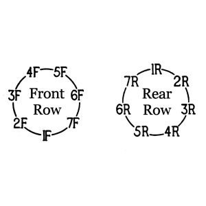
| Armstrong Siddeley Panther IIA | Panther IIA Cylinder Numbering (viewed from front) | ||
| Part 1: Power Section |
| Part 2: Auxiliary Section |
| Part 3: Induction, Ignition and Lubrication |
| General | Carburetion |
| Type = Air-Cooled Static Radial | Carburettor = One Claudel-Hobson Type A.V.T. 70.H |
| Number of Cylinders = 14 | Fuel consumption at 90% Power, Normal rpm = 5.35 pint/hp/hr |
| Cylinder Arrangement = Two Staggered Rows | Main Jet Calibration (each) = 1450 cc/min |
| Bore = 5.250" | Slow Running Jet Calibration (each) = 270 cc/min |
| Stroke = 5.500" | Power Jet Calibration = 410 cc/min |
| Displacement = 1,666.6 in³ | Venturi Diameter = 60 mm |
| Compression Ratio = 5.0:1 | Altitude Control Range = 40-50% |
| Reduction Gear = Epicyclic | Fuel Supply Pressure Range = 10.5" to 12 ft 0" |
| Reduction Gear Ratio = 0.657:1 | Fuel Level Below Joint Face (10.5" head) = 13 mm |
| Crankshaft Rotation Direction = Left Hand Tractor | Fuel Level Below Joint Face (12.0 ft head) = 5 mm |
| Airscrew Rotation Direction = Left Hnd Tractor | Ignition |
| Normal Crankshaft rpm = 2,000 | Sparking Plugs per Cylinder = 2 (1 inlet, 1 exhaust) |
| Maximum Crankshaft rpm = 2,300. | Sparking Plug Type = Lodge A2 |
| Rated Altitude = 3,000 ft | Sparking Plug Gap = 0.012" – 0.015" |
| Maximum Power at 3,000 ft = 600 bhp | Magnetos = Two B.T.H. Type SC.14-1A |
| Normal Power = 535 bhp | Port Magneto Operates All Exhaust Valve Plugs |
| Engine Dry Weight (less airscrew hub) = 1,004 lb | Starboard Magneto Operates All Inlet Valve Plugs |
| Lubrication | Contact Breaker Gap (full break) = 0.010" – 0.012" |
| Oil Specified for Summer and Winter Use = Spec. D.T.D. 109 | Distributor Gap = 0.012" – 0.015" |
| Oil consumption at 90% power, normal rpm = 12-16 pints per hour | Timing = Fixed Fully Advanced |
| Normal Flight Oil Pressure = 50 psi | Port and Starboard Magneto Timing = 29° – 31° BTC |
| Minimum Permissible Flight Oil Pressure = 30 psi | Magnetos Must Be Synchronized Within 1° |
| Minimum Warmup Oil Pressure = 40 psi at 900 rpm | Minimum Possible Timing Adjustment = 1.5° |
| Maximum Permissible Warmup Oil Pressure = 100 psi | Magneto Distributor Rotation Direction (cover end) = Anti-Clockwise |
| Oil Pressure Relief Valve Operation = 65 psi | Valve Timing |
| Minimum Oil Outlet Temperature Before Flight = 15° C | Front Inlet Tappet Clearance (cold) = 0.015" |
| Desired Oil Outlet Temperature in Flight = 70°-80° C | Rear Inlet Tappet Clearance (cold) = 0.005" |
| Maximum Oil Outlet Temperature = 95° C | Front Exhaust Tappet Clearance (cold) = 0.025" |
| Oil Circulation = 3.5 gal/min | Rear Exhaust Tappet Clearance (cold) = 0.010" |
| Firing Order | All Tappet Clearances (hot) = 0.010" |
| Firing order = 1R, 2F, 3R, 4F, 5R, 6F, 7R, 1F, 2R, 3F, 4R, SF, 6R, 7F | Inlet Valve Opens 19° BTC |
| Installation | Inlet Valve Closes 60° ATC |
| Overall Engine Diameter = 46.45" | Exhaust Valve Opens 67° BBC |
| Length (engine mounting flange to airscrew back) = 31.35" | Exhaust Valve Closes 12° ATC |
| Overall Length = 63.2" | Minimum Possible Timing Adjustment = 2° |
| Engine Mount Bolt Pitch Circle Diameter = 25" |
Part 1: Power Section
Introduction
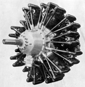
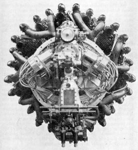
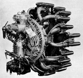
The Panther II.A. aero-engine was a geared 14-cylinder air-cooled radial with cylinders arranged in two staggered rows around a barrel type crankcase. A one-piece crankshaft, along with two connecting rod assemblies fitted with Y-alloy pistons, transferred power to the airscrew. One inlet and one exhaust valve were fitted in each cylinder head, the two valves being operated through separately enclosed push rods from a common cam drum in the crankcase front. The crankshaft drove the airscrew shaft at 0.657 times engine speed through an epicyclic reduction gear mounted in a separate casing at the crankcase front. A small degree of supercharging was effected by a fan driven from the crankshaft rear through a single compound gear wheel in which a friction clutch was incorporated; the degree of supercharging was so small that no boost gauge was fitted, but a gated throttle was employed. The fan drew carburetted mixture from a Claudel Hobson type A.V.T.70.H carburettor and delivered it to seven forked induction pipes from which the cylinders were fed. All auxiliary components such as the magnetos, gas distributor, gun gear, etc., were carried on the back of the fan casing and were driven through a layshaft, which was in turn driven through an idler wheel from the rear end of the crankshaft. The gas distributor was not normally employed, starting being effected by a hand turning gear also carried on the back of the fan casing.
Engine Description
 |
 |
| Cylinders | |
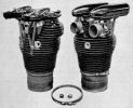
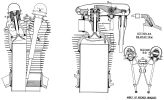
The cylinders consisted of a steel barrel, an aluminium alloy head, two locking rings, an inlet valve, an exhaust valve, valve guides, valve springs, valve spring washers, an inlet valve rocker, an exhaust valve rocker, a common rocker bracket and two valve rocker casings. The cylinder barrel was a high tensile steel forging having eight circular cooling fins towards its outer end. More than a third of the barrel length was accommodated in the cylinder socket where it was retained by being screwed into a shouldered steel sleeve or adaptor inserted into the lower end of the socket. The barrel was prevented from turning by a wedge-sectioned ring fitted between a shoulder beneath the innermost cooling fin and the outer end of the cylinder socket. The ring was split at one point in its circumference and may be contracted by a screw which causes it to force the barrel outwards from the socket and thus lock the screwed joint. The outer end of the barrel was screwed externally to receive the head which, after being screwed home, was locked by a ring screwed to the barrel beneath it. Both the ring and the inner end of the head have chamfered mating surfaces of such a camber that the head and barrel remain firmly locked at all temperatures despite the difference in the rates of expansion of steel and aluminium.
The cylinder heads were aluminium castings liberally provided with cooling fins around and over the combustion chamber and gas passages. The combustion chamber, which was approximately hemispherical, had two aluminium bronze valve seats screwed, shrunk and expanded into it on a line at right angles to the crankshaft axis; the inlet valve was on the left side of the head when the cylinder was viewed from the engine front with the head uppermost. The gas passages serving the valve seats were taken across the top of the head to the back of the casting where they terminated in bolted-on steel flanges; a boss for a priming atomizer was provided near the outer end of the inlet passage. The inlet flange provided a screwed attachment for the end of an induction pipe, and the exhaust flange presented a grooved stub to which a branch of the exhaust collector ring was clipped by a cotter screw. A projection was formed at the front of each bolted-on flange for the support of the rear end of a rocker casing. A phosphor bronze valve guide was fitted in each gas passage; the two guides were not interchangeable. An adaptor for a sparking plug was screwed and pegged into the front of the head beneath each valve, and an adaptor for a gas starter non-return valve was fitted at the rear of the head in a similar manner. A stud for an ignition cable clip was fitted at the centre of the head and supports the rear end of a. steel baffle plate for the protection of the high tension cables; the front end of the plate was attached to the rocker bracket.
The non-interchangeable inlet and exhaust valves had trumpet-shaped heads. The exhaust valve stem end was case hardened while a bearing roller was pressed and peened into the inlet valve stem end. Each valve was retained on its seat by two concentric coil springs, which at one end bore against a washer fitted around the valve guide outer end and at the other end against a second washer attached to the valve stem by the customary split cotter sleeve. A spring circlip was fitted around the valve stem below the cotter sleeve to prevent the valve from falling into the cylinder when the springs were removed.
Two valve rocker types operated the valves; one type was used for all valves of the front cylinder row and one for all valves of the rear cylinder row. The only difference between the two rocker types was the angle at which the push rod tappet sleeve socket was inclined to the rocker body. The rocker body consisted of a steel forging supported near the centre on two ball bearings lubricated through a nipple screwed into the top of the rocker. The valve operating end of the rocker carried a case hardened steel pad and the push rod operated end was split and tapped to receive a sleeve fitted with a thrust pad against which the push rod bore. When adjusted, the sleeve was locked by a clamp bolt through the rocker end. The thrust pad was a steel disc with cylindrically ground faces that provided line rolling contact with the push rod and rocker sleeve. The axes about which the upper and lower pad faces were ground were disposed at right angles to each other so as to accommodate universal movement between the push rod and sleeve. The thrust pad was a loose fit in the sleeve bore, but had to be sprung into position past a shoulder near the mouth of the sleeve.
The rocker brackets were mounted in the forked ends of rods bolted to lugs on the cylinder head front. The rods were tied together at their outer and inner ends by a built-up bracing piece shaped like an X; the assembly thus formed was known as the rocker bracket. The nuts that retained the bracing piece ends to the outer ends of the rods also retained the front ends of the rocker casings. The forked ends of the rods received short fulcrum bolts upon which the rocker bearings were supported and which, when tightened, drew the sides of the forks up against two washers fitted on each side of the rocker. The washers were of different outside diameters, the larger washer was fitted next to the rocker and was of such a size as to seal the bearing housing. A spacer was fitted at the centre of each fulcrum bolt to separate the inner races of the bearings. The bracket was attached to the cylinder head in such a position that it provided compensation for the effects of cylinder thermal expansion on valve clearances. As soon as the engine was run, the cylinder barrels and heads warmed up and expand but the rocker bracket being in the airscrew slipstream remained cool and did not expand by any appreciable amount. The expansion of the cylinder barrel causes the rocker bracket, rockers and valves to travel outwards, a movement which by itself would increase the valve clearances. At the same time as the cylinder barrel was expanding, the cylinder head and valve stems also expanded, which tended to decrease the valve clearances by bringing the valve stem ends closer to the rocker ends. A packing piece was fitted between the two parts constituting the bracket bracing piece and included a stud to which an ignition cable clip was attached. This stud and the one at the cylinder head centre also provided the attachment for a sheet steel baffle by which the ignition cables were protected from heat radiating from the cylinder head.
Each rocker was enclosed by a two-piece pressed rocker casing approximately streamline in shape, the two portions being secured together by a spring bolt and catch. The lower portions of the casing were supported clear of the cylinder head at the end of the studs integral with the inlet and exhaust flanges and at the ends of the rods which support the rockers. Two types of lower portion were used, one for the front cylinders and one for the rear; the only difference between the two types lies in the shapes of the front ends. The ends were inclined so as to be at right angles to push rods which passed through them (the angles of inclination of the push rods serving the front and rear cylinder lines differ). The same type of upper half casing was used for both cylinder rows.
 |
| Piston |
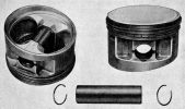
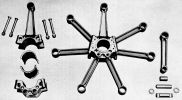
The piston and connecting rod unit consists of seven forged Y-alloy pistons secured by full floating gudgeon pins to the small ends of a connecting rod assembly. The connecting rod assembly consists of one master and six auxiliary rods. This assembly is described in detail below.
The piston had a concave head beneath which two plain compression rings and one grooved oil scraper ring were fitted in separate grooves. All rings were diagonally jointed and free to turn in their grooves. Numerous oil return holes were drilled through the centres of the scraper rings, through the bases of the scraper ring grooves and in the pistons beneath those grooves. The piston skirt was relieved to accommodate bosses for the hollow gudgeon pins, which located between circlips that were sprung into grooves in the gudgeon pin bores. The pistons were fitted with the longer skirt edge on the inlet valve side of the cylinder. In early engines, such pistons were fitted to the master connecting rods only; pistons with equal length skirts were fitted to the auxiliary rods.
 |
| Connecting Rods |
The I-shank master rod housed a white-metal-backed steel bearing shell between the big end and cap. Both cap and big end were flanged and the flanges drilled to receive the ends of the knuckle pins by which the auxiliary rods were attached. The joint between the big end and cap was V-shaped and was not taken through a crankpin diameter but midway between the knuckle pin sockets for the auxiliary rods serving cylinders 2 and 3, and 6 and 7. The cap accommodates more than half of the bearing shell and has the horns opened out to permit the fitting and removal of the shell. Four bolts secure the cap to the big end and break into the sockets for four of the knuckle pins. The bearing shell was split across a diameter and was flanged at each end. The flanges around the ends of the portion received by the cap were notched to engage locating pegs fitted in the cheeks of the cap. No oil grooves were used in the bearing shell. The rod small end was drilled with eight oil transfer holes and carried a bronze floating bush similarly drilled. The four knuckle pins fitted to the sockets broken into by the rod cap bolts were notched to clear the bolts and were located by those components against end movement. These pins were push fits in the rod and cap. The two remaining pins were of larger diameter at one end than at the other and were located against end movement by circlips carried in the cap; these pins were light drive fits in the cap. Both types of pin were hollow, the notched pins being bored eccentrically and the plain pins concentrically.
The I-sectioned shank auxiliary rods had a housing for a floating bronze bush formed at each end. Both bushes and housings were each drilled with eight oil transfer holes. The gudgeon pin bushes were interchangeable with those of the master rods and were larger than the knuckle pin bushes. Hardened steel spacer washers were fitted between the auxiliary rod knuckle pin ends and the master rod cheeks; the washers bore on the rod ends and not on the bushes.
 |
| Crankshaft |
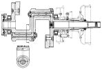
No center main bearing was provided, which was a design limitation of the engine. The flanged nut, in conjunction with a flanged sleeve around the annulus boss, limited the crankshaft end float by fixing it between the sleeve and a bush fixed in the crankcase unit. No locking device was provided for the flanged nut; the front nut was serrated externally and behind it was fitted a thick aluminium washer of the same external diameter and bearing similar serrations. The washer was keyed to the shaft and the nut tightened till the serrations around the two components registered; an internally serrated sleeve of a thickness nearly equal to the combined thickness of the nut and washer was then passed over the two components so as to lock them together. The sleeve was retained against loss by a circlip fitted around the nut.
A compound gear wheel was keyed to the shaft behind the rear main roller bearing inner race; it and the race were secured by a nut screwed to the shaft end and locked by a split taper pin. The gear wheel was of composite construction, the smaller portion being bolted and spigoted to the rear face of the larger. The larger ring of teeth transmitted the drive, through an idler wheel and auxiliary drive shaft to the magnetos and other auxiliary components. The smaller ring of teeth drove the fan through an intermediate gear wheel in which a centrifugal friction clutch was incorporated. A shoulder was formed in the rear crankshaft journal bore to receive the rear fan bearing outer race.
The crankshaft and crankpin journals were bored for lightness and lubrication. Drillings in the front and centre crankwebs connected the crankpin bores and the main journal front end. The shaft was bored concentrically and the pins eccentrically. The crankpin bores were fitted with long, interchangeable, duralumin plugs that were drilled so as to transfer oil directly from the crankweb ducts to two holes drilled in a groove on each side of both pins. This construction prevented sludge from collecting in the crankpin bores and obstructing the oil holes when the engine was cold. The plugs were detachable for cleaning, being secured by nuts and washers and being prevented from turning by large setscrews. The crankshaft bore, where it broke through the front crankweb, was sealed by a duralumin plug, which was a force fit in the end of the shaft in which it was located behind a shoulder by a circlip sprung into the end of the bore. A plug having a small central aperture was fitted in the front end of the shaft where it was secured by a grub screw.
 |
 |
 |
 |
 |
 |
| Front Cover | Intermediate Bearing Housing | Crankcase | Rear Diaphragm | Induction Casing and Cover | |
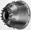
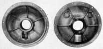
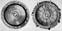
The front cover enclosed the reduction gear, housed the airscrew front bearing and provided mounting for the main oil pump unit. It was bolted and spigoted to the intermediate bearing housing, which was in turn bolted and spigoted to the crankcase. The intermediate bearing housing was in the form of a diaphragm that received the bush in which the front end of the crankshaft and the reduction gear annulus hub were supported. It also steadied the oil pump driving spindle upper end.
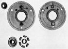
The crankcase housed the crankshaft, valve timing gear and front main roller bearing; it also provided the cylinder mountings, two breathers, an oil filter and a lifting eye. The rear diaphragm, which was bolted and spigoted into the rear end of the crankcase, housed the rear main roller bearing and provided mountings for the fan intermediate gear and idler wheel spindles. The fan induction casing provided the fan volute chamber and the front portion of the fan chamber; it received the inner ends of the induction pipes and provided rear fan bearing mounting. The fan induction casing cover closed the fan chamber, housed the auxiliary drive shaft and provided the mountings for magnetos, hand turning gear, the auxiliary drive unit, and the carburettor and induction elbow unit.
The crankcase was a Y-alloy forging with a shallow extension beyond the closed front end that housed the cam drum and associated valve timing gear parts. The annulus was bolted and spigoted to the ring concentric with the extension exterior. The tappet guides were accommodated in fourteen sockets around the extension exterior and in the ring. The front main roller bearing outer race was trapped between a lip at the front end and a ring sprung into the rear end of a steel housing shrunk into the crankcase front end. A ring nut screwed and peened to the front end of the housing drew a flange around the rear end up against a seating in the crankcase. The housing was prevented from turning by a number of projections on the flange that engage notches in a lip around the seating in the crankcase.
The 14 cylinder sockets were arranged in two staggered rows, being machined in deep bosses that projected from the forging's main body. Each socket housed an internally threaded steel sleeve or adaptor, shouldered at its inner end to bear around the lower end of the socket in which it was an easy fit. The adaptor was secured in any one of twelve positions by a peg fitted in the wall of the socket and secured from the outside by a circlip; this peg took no part in the adaptor location once the cylinder's base locking ring was tightened. A lifting eye was screwed into a boss between the two uppermost cylinder sockets in the front row and carried a calibrated jet through which oil was injected into the crankcase from the main pressure system. A facing for the attachment of an oil sump and strainer was formed between the sockets for the two lowest rear-row cylinders. A breather was fitted to the casing on each side of the socket for the uppermost rear-row cylinder to communicate with a space between the crankcase and induction casing.
The rear diaphragm was a duralumin forging that was spigoted and dowelled to the crankcase rear end and secured by 21 studs. A housing for the rear main roller bearing outer race, similar in all respects to the front housing, was fitted at the diaphragm centre. Above and below it were mounted the spindles for the idler wheel and the fan intermediate gear.
The induction casing was machined from an aluminium alloy casting. The central aperture received a steel housing for the rear fan bearing outer race, the housing being secured by 6 bolts through a flange at its rear end. The bearing's outer race was retained between a lip at the housing rear end and a ring sprung into the front end. The housing was sealed at the rear end by a spring-loaded gland ring fitted at the back of the fan bearer to bear on a facing at the retaining flange rear. A large socket in the front of the casing above the bearing housing received the auxiliary driving shaft gear wheel bearing flanged outer race and the hole in the rear of the casing in line with it steadies the front end of a sleeve through which the shaft passes and which bridges the passage between the fan chamber and volute. The smaller holes in the casing above and below the fan bearing housing received the rear ends of the spindles mounted on the rear diaphragm for the support of the idler and intermediate gear wheels.
A deep trough around the casing's rear face formed the volute chamber to which the fan delivered, and seven equally spaced bosses around its exterior received the inner ends of the induction pipes. Each boss contained a ring of Dermatine packing that was compressed by a duralumin ring borne on by a screwed sleeve around the pipe's end and against a conical shoulder at the inner end of the boss. The sleeve was screwed into the outer end of the boss and was locked by a spring-loaded plunger that engaged one of several axial grooves in the threaded portion. The dished flange that projected to the rear of the volute chamber provided the means for attaching the engine to the airframe. The 14 slotted holes through the flange's web portion received the high tension cables. The casing was spigoted, dowelled and retained by numerous bolts to the back of the crankcase.
The induction casing cover was machined from an aluminium casting. The casing front end was circular, and was spigoted, dowelled and retained by numerous studs around the volute chamber of the induction casing. The inclined facing at the casing centre back was for attaching the induction elbow and surrounds one end of a short elbow-like intake gas passage that led to the far chamber centre. The small studs fitted in the stiffening ribs on the casing back received high tension cable clips, and the two large studs secured a bracket that steadied the induction elbow.
The box-like projection (hereafter referred to as the drive housing), above the intake gas passage received the two magnetos, the layshafts by which they were driven, the hand turning gear and the auxiliary drive unit; it also housed the auxiliary drive shaft through which the various components were driven. The magnetos and the layshafts through which they were driven were mounted one at each side of the drive housing, the layshafts being screwed into sockets and the magnetos studded to facings. The hand turning gear was mounted at the housing rear end, and the gas starter and auxiliary drive unit was mounted above the housing. The auxiliary drive shaft passed through the drive housing from front to rear. A flanged sleeve was screwed into the front of the drive housing to surround the auxiliary drive shaft, and had its front end steadied in a socket in the induction casing. This sleeve bridged the passage between the fan and volute chambers and thus sealed the fan chamber and volute from the crankcase and drive housing. The sleeve was prevented from turning by a spring-loaded bolt mounted in the boss into which the sleeve was screwed; the end of the bolt engaged between castellations around the sleeve flanged end. A steel housing for the auxiliary drive shaft rear bearing outer race was secured by a flange to a wall cast across the interior of the drive housing just in front of the mounting flange for the hand turning gear. The race was held between a lip at the front end of the housing and a ring nut, screwed into the rear end. Oil draining from the gas starter and auxiliary drive unit collected in a sump cast between the drive housing and the intake gas passage, and was withdrawn by the auxiliary oil pump through a small gauze filter screwed into the sump rear end.
The intermediate bearing housing was machined from an aluminium alloy casting and was spigoted, dowelled, and retained by 14 studs to the crankcase front. The central housing accommodated a phosphor-bronze bush that supported the reduction gear annulus, the bush being retained by six studs through a flange around its front end. An internal groove was turned at the centre of the bush to connect up a ring of six large oil transfer holes spaced so that one registered with the upper end of a duct in the bush housing. The lower end of this duct received a bush that supported the upper end of the oil pump driving spindle. The driving spindle was hollow and through it the pump delivered the oil supply to the crankshaft. A steady for the oil pump casing upper end was formed in the web of the intermediate bearing housing beneath and in line with the afore-mentioned duct.
The front cover, machined from an aluminium alloy casting, was spigoted and dowelled to the intermediate bearing housing, where it was retained by the same studs which retain the housing to the crankcase. The outer race of the airscrew shaft front bearing is housed in the front end of the cover where it is gripped between an internally toothed ring plate of steel and a cover plate of duralumin. The ring plate is fitted on the inside of the cover and the cover plate on the outside, the two components being drawn up to the end of the cover by fourteen common bolts. The ring plate provides an anchorage for the front end of the reduction gear sun wheel, and the cover plate seals the front end of the cover by making an oil tight joint with the cylindrical shank of a nut which secures the inner race of the front bearing to the airscrew shaft. A facing for the attachment of the main oil pump unit is provided on the underside of the front cover and an inspection window, through which the magneto timing mark on the reduction gear annulus may be observed, is provided on the upper surface of the cover; this window is normally sealed by a cover plate. The four studs shown on the cover were for the attachment of cowling supports.
 |
 |
|
| Cam Drum Components and Diagram | ||
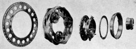
The sun wheel was formed as a steel sleeve, keyed to the crankshaft and gripped between the front main roller bearing inner race and the front cam drum bearing inner race. A ring of thirty-six teeth was machined at the sleeve front end and a shoulder was formed at the rear end to provide the rear cam drum unit bearing inner race.
The cam drum unit was of composite construction and comprised the cam drum, the cam drum bearer or timing casing, three compound planet wheels and their spindles, a bevel wheel that drove the oil pump, a ball bearing and a ring of caged rollers. The steel cam drum had four rows of cams around it, with four equally-spaced cams in each row. The front cam row operated front cylinder row inlet valves; the second cam row operated rear cylinder row the inlet valves , the third and fourth cam rows operated exhaust valves in the front and rear cylinder rows respectively. The drum was provided with a deep internal web by which it was attached to the cam bearer, nine bolts and the ends of the planet pinion spindles being employed to effect the attachment.
The cam bearer, or timing gear housing, was a steel sleeve supported at its front end upon a ball bearing and at its rear end upon a ring of caged rollers. The ball bearing was mounted on the crankshaft in front of the sun wheel, with rollers around the shoulder at the sun wheel rear end. The sleeve was flanged at each end, the rear flange being circular and the front flange star shaped. The three planet wheels were mounted between the flanges and meshed with the sun wheel through openings in the sleeve. In addition to the sockets for the planet wheel spindle rear ends, the rear flange was drilled with the nine holes for the attachment of the cam drum, which was mounted around a spigot on its rear face; there were also numerous lightening holes in the flange. Six holes were drilled in the star-shaped front flange for attaching the bevel wheel; three of the holes were also used to receive the planet wheel spindle front ends. A ring was sprung into the sleeve front end to retain the ball bearing outer race against a shoulder in the sleeve.
The pinion (11 teeth) and the gear wheel (33 teeth) portions of each planet wheel were integral, being formed at the front and rear ends respectively of a hollow boss. The boss was fitted at each end with a flanged phosphor bronze bush for its support on the spindle. The spindle had a collar towards its rear end, which was received in a socket in the cam bearer rear flange and was drawn up to the cam drum web front face by a nut at the back of the web. The spindle was squared to the rear of the collar and fitted a square hole in the web. The spindle front end was shouldered against the cam bearer front flange rear face and projected through both that flange and the bevel wheel flange attached thereto. A nut screwed to the spindle front end retained the bevel wheel, which drove the oil pump; the nut also bound the bearer flange solidly to the spindle. In appearance, the bevel wheel closely resembled a crown wheel, the inclination of the teeth being very slight. A shim, by which the depth of the wheel mesh of was determined, was fitted between the bevel wheel and cam bearer.
The annulus had eighty-four teeth. The teeth were machined around the bore of a ring attached to the crankcase through a deep supporting flange drilled with 18 lightening holes. The flange outer edge was spigoted for reception in the front crankcase projection that also received the tappet guide inner ends. There were 7 unequally pitched studs in the crankcase facing and 45 equally pitched stud holes around the flange, an arrangement that permitted the annulus to provide a minimum timing adjustment of 2°.
 |
 |
 |
| Valve Gear, Tappets and Push Rod Covers |
||
One tappet design was used to operate all push rods. The tappet had a hollow cylindrical body that was forked at the inner end to receive a roller that was of considerably greater diameter than the tappet; it rotated about a helically grooved pin which, in turn, floated in the forked tappet end. Four oil retaining grooves were machined around the tappet centre the along with a circlip groove close to the outer end. The circlip prevented the tappet from falling through the guide when the cam drum was removed. The push rod end was received in a hemispherical socket in the tappet outer end.
Two tappets that operated the push rods of each cylinder were accommodated, one in front of the other, in a common aluminium guide. The lower end of each tappet guide bore was slotted to take the projecting portions of the tappet roller, a construction that prevented tappet rotation. The guide inner end was received in the rim which projects from the closed front end of the crankcase; the outer end was received in the crankcase outer wall. Each guide was secured by two bolts. The projecting bolt heads engaged recesses in the crankcase wall and thereby prevented the guide from turning. The hooked projections on the bolts beyond the heads, by bearing on the sides of the guide, prevented the heads from bending under the eccentric loads to which they were subjected. A circlip fitted around the stem of each bolt prevented it from falling through into the timing gear after the retaining nut has been removed. In addition to retaining the tappet guides to the crankcase, the bolts also secured the push rod inner end guides covers.
The non-adjustable push rods had tubular bodies with case-hardened plugs soldered into each end. The tube outer ends were swaged down to a taper that received collars against which the push rod spring lower ends bore. The outer end plugs were flat so as to bear on the cylindrically-round rocker tappet sleeve thrust pads. The inner plugs were ball-ended so as to mate with the recessed tappet ends. The push rods were of three different lengths. The shortest was used for both front cylinder valves; the longest for rear cylinder exhaust valves; those of intermediate length for the rear cylinder inlet valves.
Aluminum push rod covers enclosed each push rod. The covers' inner ends were accommodated in a common magnesium alloy bracket bolted to the tappet guides' outer ends. The tubes were swaged to a narrow funnel shape and had internally-lipped duralumin caps riveted to their outer ends. Four equally spaced radial notches were machined into the lip edges and a like number of recesses were machined in the lip under surfaces between the notches. The caps were held in contact with the rocker casings by coil springs anchored to the outer ends of the push rods by the sleeves. The spring outer ends bore on washers anchored to the caps by four radial lobes that projected from their edges. These lobes engaged the recesses in the caps and, when the washers were being fitted, were passed through the notches in the caps. Four recesses were provided in the outer faces of the caps to register with four rivets in the under surfaces of the rocker covers. The brackets that received the cover tube inner ends featured a felt ring in a groove at the outer end of each socket to render the tube joint oil tight. Because of variations in length and inclination of the various push rods, three types of cover tube and two types of bracket were required. The shortest tubes were used for all front-row cylinders; longer tubes that had a diameter step down at the inner end was used for the rear-row exhaust rods; the third tube type was used for the rear-row inlet rods. Of the two bracket types, those marked F were used for all front-row rods and the other type for all rear-row rods. The action of retaining the cover tube outer ends against the rocker casings was merely auxiliary to the main purpose served by the springs fitted to the outer ends of the push rods. These springs were primarily intended to retain the push rod inner ends in engagement with the tappets and thus eliminate chatter and consequent wear.
Airscrew Shaft and Reduction Gear
 |
 |
 |
| Reduction Gear Components and Diagrams | ||
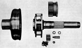
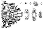
The airscrew shaft was mounted in line with the crankshaft from which it was driven through an epicyclic reduction gear at a 0.657:1 ratio. The reduction gear, which consisted of an annulus fixed to the crankshaft, five plain planet wheels carried by the airscrew shaft and a sun wheel anchored to the front cover, was housed between the front cover and the intermediate bearing housing.
The annulus was splined to the crankshaft front end and centered between two phosphor-bronze cones. An air-hardened steel bearing sleeve for reception of the intermediate bearing was mounted on the annulus boss. The sleeve was prevented from turning on the annulus boss by a number of radial projections around a flange at its front end. These projections engage a like number of notches in a lip around the back of the annulus cup so that two oil transfer holes through both sleeve and annulus were in register. A nut screwed to the crankshaft retained the annulus and the airscrew shaft rear bearing inner race. When this nut was tightened, the front centering cone, annulus and rear centering cone were forced backwards until a lip at the bearing sleeve rear end was forced against the crankshaft center nut. As a result, the crankshaft end float in the crankcase was limited to the difference between the length of the intermediate bearing and the distance between the flange and rear end of the sleeve. A cone shaped oil baffle was riveted to the front of the annulus; the purpose of this baffle will be described later. A timing mark for setting the port and starboard magneto timing was engraved upon the annulus.
The airscrew shaft was hollow and at the rear end had a five-sided boss formed with pockets to take the planet pinions. The shaft front end was splined for engagement with the airscrew hub, which was centered on the shaft between two phosphor-bronze centering cones. The rear cone, which was slotted through one side, abutted against a nut that retained several bearing components in place. The front cone, which was split across a diameter and grooved internally at the front end, was forced up into the hub bore by a nut screwed to the shaft end. The nut was locked as follows: its front end projected beyond the shaft end and was splined internally to engage a spring-loaded sleeve carried in the shaft front end. The sleeve was keyed to the shaft through projections that worked in slots in the shaft end and was closed at the front end for the spring abutment. The spring rear end bore on a plug pressed and pinned into the shaft end. When it was desired to unscrew the nut, the sleeve was forced inwards until its front end disengages the nut bore.
The airscrew shaft rear end was supported on a roller bearing, the inner race of which was carried by the crankshaft. The bearing outer race was housed in the shaft rear end where it was retained against a shoulder by a spring ring. The shaft was also supported in front of the planet pinions and sun wheel in a second bearing that took both thrust and journal loading through balls of unusually large diameter carried in very deep grooves. The bearing inner race was split circumferentially to permit the assembly of the balls, and was located positively upon the shaft between a nut at the front end and a spacer washer and the sun wheel bearing inner races at the rear end. The nut made an oil seal with the front cover. A floating bush was fitted in the airscrew shaft bore beneath the previously-mentioned bearing and, until there was sufficient airscrew thrust to take up the bearing end float, transmitted the airscrew shaft journal loading to the crankshaft front end.
The planet pinions were hollow and supported upon hollow pins fitted through the pockets in the boss at the airscrew shaft rear end. The pinion bores were ground and provided the outer races for three rings of uncaged rollers that also bore directly around the pins. The rollers were located between lips at the pinion ends and steel rings mounted on the pins. The pins, which were push fits in the airscrew shaft boss sockets were of larger diameter at the front than at the rear. They were retained by nuts that drew shoulders at their rear up against the ends of their sockets. Each pin was keyed into the rear socket in such a position that an oil hole, drilled from an oil collector lip at the airscrew shaft boss rear, registered with a hole in the pin end. Oil passed through this hole to the pin bore and was then delivered via a staggered ring of four transfer holes to the pinion bore. The pins were bored from the front ends and those ends sealed by screwed duralumin plugs.
The sun wheel was constructed as a sleeve supported on the airscrew shaft through a ball and roller bearing. The sun wheel rear end was situated beneath the planet pinions and was machined with a ring of teeth for their engagement; the front end was also toothed and was locked to the front cover by being engaged in the internally toothed ring plate fitted therein. The ball bearing on which the sun wheel front end was supported was of standard type. The bearing outer race was positively located in the wheel between a shoulder and a spring ring; the inner race was positively located upon the airscrew shaft immediately in front of the sun wheel rear bearing inner race. The rear bearing was a roller bearing of special design; the outer race was formed by the ground bore of the sun wheel rear end and the inner race around the rear end of a steel sleeve gripped between the front bearing inner race and a shoulder around the airscrew shaft. The sleeve front end was screwed to engage an extractor tool since the sleeve was a tight fit on the airscrew shaft.
The airscrew hub consisted of a flanged sleeve, splined, centered and retained on the airscrew shaft, and a loose flange splined to the sleeve front end. A pressed steel boss for the mounting of a hucks starter claw was secured to the loose flange with eight taper-headed bolts, the bolts being fitted with locating pegs to prevent them from turning. Eight long bolts retained the loose flange and the airscrew to the flanged sleeve.
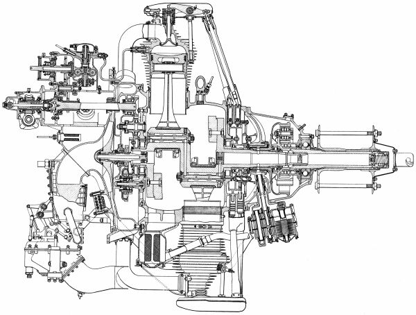 |
| Armstrong Siddeley Panther IIA General Arrangement |
On to Part 2: Auxiliary Section