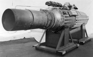
XJ37 Turbojet (NARA)
The Lockheed L-1000 (XJ37) Turbojet
Compiled by Kimble D. McCutcheon
Published 29 Jan 2022; Revised 18 Oct 2023
Author’s Research Overview
Precious little has been written about Nathan Price and the Lockheed L-1000 Jet Propulsion Engine. This article attempts to create a factual baseline with the hope that future researchers may enhance it. It is based almost completely on primary sources, what few there are. The National Archives and Records Administration (NARA) lost a microfilm reel covering Materiel Command (MatCmd) Engineering Division Power Plant Laboratory memorandums for most of 1943. The author suspects that this missing microfilm reel would have been a significant information source. The J37 Case History and J37 correspondence documents deal primarily with contracts, costs and schedules, and only peripherally address technical details. I have preserved most of the details despite the fact they are not strictly technical because I think they illuminate how a very early jet engine was to be built, developed and tested.
Very little is known about the engine’s life at Menasco, and practically nothing about it once it went to Wright Aeronautical. If anyone can add to the story USING PRIMARY SOURCES, I would be very pleased to hear from you via the "webmstr" link at the page bottom. In hopes of promoting further research on this topic, I have made nearly all of my primary source material available to AEHS members; please see the Reference list at the page bottom.
Nathan C. Price
According to Ancestry.com 1940 Census records, Nathan Cozens Price was born in New Jersey about 1905, making him 35 in 1940. At that time he lived in Los Angeles, California with his wife, Constance. Price and Genevieve Sweetser Wood were married on 15 Apr 1952 and lived in Hollywood, California. His patent filings indicate he lived in Berkeley, Hollywood, Los Angeles, and St. Helena, California; Seattle, Washington; Barcelona, Spain; Mexico City, Mexico and Geneva, Switzerland. At this point, little can be found about Price's early life, education and early work history. Clearly, a deeper dive into Price's biography is in order.
In 1930, Price went to work for Doble Steam Motors of Emeryville, California where he designed high-pressure, high-capacity boilers and their controls. He was also involved in the design of a two-cylinder steam engine for William J. and George Besler, which they used in their steam-powered Travel Air 2000, which flew in 1933. When Doble Steam Motors folded in 1931, Price may have worked briefly for the Besler Corporation, also of Emeryville, which acquired most of the Doble assets.
Price next worked for Boeing, which he apparently tried to interest in steam-powered airplanes, to no avail. However, Boeing was interested in pressurizing the cabin of its Model 307 airliner. Price invented and patented the cabin pressure regulator system that made this possible, along with other cabin heating schemes and controls. (U.S. Patents 2,208,554, 2,193,141, 2,251,420, 2,193,142, 2,231,295, 2,186,344, 2,620,719, 2,276,371, 2,280,128)
Price was a steam automobile and airplane man, with most of his early patents aimed at new kinds of small, lightweight boilers and their control systems, which were applicable to aircraft and other vehicles. Steam generation at high altitude required a way to pressurize the air to sea level pressure and deliver it at a constant rate to the steam generator burner. Sometime in the mid-1930s he hit on the idea of connecting a centrifugal compressor to a gas turbine driven by the hot gasses coming out of a burner between the compressor and turbine. Hot gasses exiting the turbine then traveled to a boiler go generate steam, which drove steam turbines connected to propellers. This is a circuitous way to power an airplane, but was nevertheless a stepping stone to a turbojet as it contained a compressor, burner and turbine. (U.S. Patent 2,223,856) It was not a huge leap to use only that gas jet to propel an airplane.
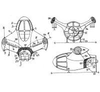
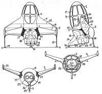
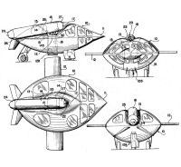
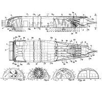
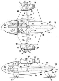
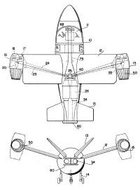
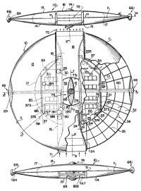
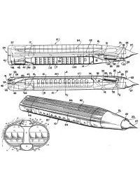
While Price had a fertile mind and an impressive command of the applicable aerodynamic and thermodynamic principals, his command of the practical was a bit less stellar. His inventions were often overly complex and some were downright fantastical. Still, one cannot help but be impressed with Price's 98 patents and cannot help but wonder how he found time for any real work! Price's patents covered astounding technological breadth, predicting just about every gas turbine advancement that has come along since, including multi-spool engines, ducted fans, mixed-flow compressors and turbines, air-cooled turbine blades, and variable-geometry supersonic inlets, to name but a few.
 |
 |
 |
 |
| US 2,610,005 | US 2,668,026 | US 2,953,900 | US 2,973,921 |
 |
 |
 |
 |
| US 2,762,584 | US 2,780,424 | US 3,103,324 | US 3,148,848 |
The Lockheed L-133 Airplane and L-1000 Engine
Price went to Lockheed Aircraft Corp. in 1941 as a consultant on General Electric turbosupercharger installation for the Lochkeed XP-49. [StPeters 90] There he met Lockheed Chief Research Engineer Clarence "Kelly" Johnson, who he told about his gas turbine concepts. Johnson was working on a high-speed airplane design that seemed a natural fit with Price's engine. Thus was born the Lockheed L-133 airplane and L-1000 engine. [Schlaifer, 88, 448-450]
Chronology
 |
| Lockheed L-133-0-10 Wing Area = 325 ft² |
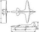
In a 30 Mar 1942 letter to the Materiel Command (MatCmd) Experimental Engineering Section Chief, Lockheed Vice President and Chief Engineer Hall L. Hibbard submitted a proposal introducing the Lockheed Model L-133, a " …very advanced design for a single place interceptor…", and offered to send Lockheed engineers to Wright Field to discuss the proposal. In addition to the usual documents detailing design features, weight and balance, model specification, performance, stress data, etc., the proposal included Lockheed Report No. 2579, "Manufacturer's Preliminary Brief Model Specification, Jet Propulsion Unit." This is the first mention of the Lockheed L-1000 (XJ37 Air Corps designation) turbojet power plant, although at the time MatCmd and Lockheed referred to it as the "power plant". [CHD 2-3]
First Generation L-1000
The author knows of no one that has yet produced a genuine Lockheed L-1000 drawing, let alone an early one. The following is the author’s best guess at the L-1000 version that Lockheed first proposed to MatCmd. It is taken from U.S. Patent No. 2,540,991 and discussions that appear later in MatCmd correspondence. An axial flow compressor and a three-stage centrifugal compressor comprised the early L-1000 compressor section. We do not know the number of axial compressor stages, but we do know it was driven through a fluid coupling, making it variable speed. This was done to accommodate lower atmospheric pressure at altitude; the compressor was driven at a slow speed at sea level and at its maximum speed at maximum altitude (50,000 ft). Air exiting the axial compressor passed through a liquid-cooled intercooler before entering the first centrifugal stage, and then through a second liquid-cooled intercooler before passing into the second centrifugal stage. Lockheed maintained all this intercooling was necessary to keep the turbine inlet temperature within reason. Lockheed planned to circulate the intercooler coolant through radiators in the wing skin. The patent presents the option of using a multi-cylinder reciprocating compressor instead of the three centrifugal stages; this option was not exercised. Air exiting the third centrifugal stage entered can-annular burners where fuel was added and ignited. Price had been designing burners for years but appears to have stumbled with the L-1000 combustion chambers; they were apparently too short and did not work correctly until after Wright Aeronautical had taken over the project in 1948 [StPeters 106]. Lockheed first proposed a five-stage turbine, but later reduced this to four stages. Price envisioned air-cooled turbine blades and nozzles, providing air passages throughout the engine. (U.S. Patent 2,448,825) Following the turbine section was an afterburner with a variable area nozzle. In the engine's center was a bevel bull gear that drove several accessory drive pinions and shafts. Some of these powered the usual range of accessories — generators, starters, hydraulic pumps, fuel pumps, etc. Some were intended for much more novel applications, including blowers for boundary layer control and a scheme to drive the landing gear wheels, promoting a faster takeoff.
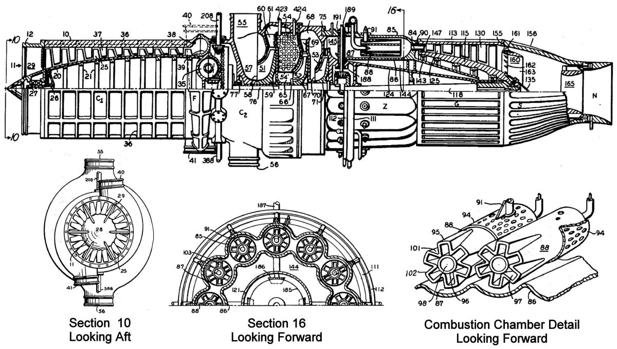 | |||
| C1 = Axial Compressor C2 = Centrifugal Compressor G = Turbine N = Nozzle S = Secondary Combustion Chamber Z = Combustion Chambers 10 = Housing11 = Annular Opening 12 = Grooved Spigot 20 = Rotor Shell 21 = Axial Reinforcing Ring 25 = Impeller Blades 26 = Hollow Spindle 27 = Bearings 28 = Forward Bearing Housing 29 = Struts 35 = Hydraulic Coupling 36 = Longitudinal Ribs 37 = Diffuser Vanes 38 = Outlet Housing 39 = Outlet Housing 40 = Outlet Spigot 41 = Outlet Spigot |
51 = Centrifugal Stage 52 = Centrifugal Stage 53 = Centrifugal Stage 54 = Intercooler 55 = Inlet Nozzle 56 = Inlet Nozzle 57 = Annular Chamber 58 = 1st Stage Inlet 59 = 1st Stage Impeller 60 = Diffuser Vanes 61 = Annular Chamber 65 = Intercooler Outlet 66 = 2nd Stage Inlet 67 = 2nd Stage Impeller 68 = Annular Chamber 69 = Diffuser Vanes 70 = 3rd Stage Inlet 71 = 3rd Stage Impeller 75 = Diffuser Vanes 77 = Forward Bearing 78 = Rear Bearing 84 = Vanes |
85 = Housing 86 = Shroud 87 = Barrels 88 = Burner Tubes 90 = Nozzle Ring 91 = Strut 94 = Perforated Cylindrical Sleeve 95 = Concentric Tube 96 = Inner Burner Tube 97 = Concentric Tube 101 = V-Shaped Flute 102 = Burner Outlet 111 = Air Manifold 112 = Fuel Manifold 113 = Housing 115 = Rotor 118 = Tapered Shaft 124 = Conductor Bar 125 = Turbine Blades 130 = Stator Blades 135 = Conical Cap |
143 = Baffle 144 = Annular Space 145 = Combustion Chamber Forward End 147 = Cooling Air Nozzle 155 = Secondary Combustion Chamber Attachment 156 = Housing 160 = Annular Baffle 161 = Struts 162 = Heat-Resistant Strut Leading Edge 163 = Refractory Strut Trailing Edge 165 = Moveable Nozzle Throat 186 = Bevel Pinion 187 = Auxiliary Drive Shaft 188 = Auxiliary Pinion Shaft Bearing 189 = Auxiliary Pinion Shaft Bearing 191 = Auxiliary Pinion Shaft Stuffing Box 208 = Accessory Drive Shaft 388 = Boundary Layer Control Fan Drive 423 = Intercooler Coolant Inlet Pipe 424 = Intercooler Coolant Outlet Pipe |
In his 28 May 1942 reply, MatCmd Experimental Engineering Chief Col F.O. Carroll, accepted Lockheed's offer to send representatives to Wright Field. Carroll observed that Lockheed's L-133 proposal represented goals that could be achieved only after a long, elaborate research and development effort, was too complex an undertaking for a single project and suggested a more conventional airplane be discussed at the upcoming conference. He further observed that the power plant data submitted with the proposal was insufficient for evaluation and that the power plant and aircraft development should be separate endeavors. [CHD 4]
During the week of 3 Aug 1942, Lockheed's Hibbard and Kelly Johnson met at Wright Field with Technical Staff Chief Col H.Z. Bogert, MatCmd Engineering Division Chief Col L.C. Craigie and Col M.S. Roth. The participants agreed that Wright Field representatives would visit Lockheed during the week of 17 Aug to discuss the proposal, including the power plant, in more detail. [12 Aug 1942 letter, Hibbard to Carroll, CHD 5]
 |
| L-133 Intercooler Radiator Scheme |
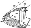
The proposed L-133 skin radiators had been replaced with a cooling core located within two aft augmenters, which Lockheed hoped would increase thrust with a small empty weight penalty. Lockheed was still toying with the idea of takeoff assistance by driving the landing wheels and intended to explore flap boundary layer control by wind tunnel testing. MatCmd suggested the power plant was too complicated and Lockheed was trying to simplify it, including postponing selection of accessories until later. Lockheed objected to MatCmd's push to eliminate the compressor interstage intercoolers, stating that turbine inlet temperature would limit burner fuel flow and ultimately, power plant thrust. MatCmd was concerned about intercooler battle damage, but Lockheed thought intercooler circuit redundancy would mitigate this. MatCmd was also critical of the variable-speed fluid coupling, but Lockheed pointed out that axial compressor speed had to vary considerably with altitude and that the fluid coupling design incorporated variable vanes to minimize coupling heat dissipation. Lockheed agreed to eliminate one set of accessory drive gears.
MatCmd had apparently questioned the number of compressor stages but Lockheed stated that the compressor efficiency was dependent on careful aerodynamic study, which had predicated the number of stages. Lockheed opined that the cooling core weight was offset by thrust gain and that the maintenance issues resulting from radiator choice would be favorable with the proposed scheme. Detailed weight studies were under way, power plant weight was projected to be about 1,700 lb, and the weight study would be complete in a week. [8 Sep 1942 letter, Hibbard to Carroll, CHD 6-8]
In a 21 Oct 1942 conference attended by Cols Carroll, Bogert, Keirn, Roth, Fighter Branch Chief Col R.P Swafford and Lockheed representatives, Col Keirn requested additional power plant technical material. Lockheed pointed out that more accurate performance data at various altitudes and fuel flows would require additional sheets showing families of curves for each affecting variable. The resulting document would allow one to pick thrust and specific fuel consumption for any speed, altitude, power plant air consumption and turbine inlet temperature. Lockheed expected to deliver the more refined power plant data around 1 Dec 1942.
Apparently Lockheed had plans to coat the combustion chamber interiors with carborundum, but Col Keirn's remarks relating MatCmd experience with carborundum refractory material's effects on downstream turbine buckets had caused Lockheed to change the combustion chamber design, making use of chrome-nickel steel cooled by excess air. The most recent power plant weight estimate was 1,620 lb, which included the lubrication system and necessary accessories. The external intercooler core weight was estimated to be 140 lb per power plant. [24 Nov 1942 letter, Hibbard to Carroll, CHD 9-10]
In a 2 Jan 1943 IOM from Carroll, now a Brigadier General and Engineering Division Chief to Power Plant Laboratory (PPL) Chief Col Edwin R. Page, Carroll stated that it was essential for MatCmd to decide on further action regarding the L-133 and its power plant. Since the aircraft performance Lockheed had estimated depended on successful engine development, a feasible engine development program was an essential first step. The various airframe development phases should be timed to power plant development so that little development effort is wasted due to engine difficulties. Brig Gen Carroll suggested the power plant and airframe development be handled separately while also being closely coordinated. The PPL should handle engine development while the Aircraft Projects Section handled the airframe development phases. Brig Gen Carroll invited Col Page's comments. [CHD 12]
Col Page responded to Brig Gen Carroll's 2 Jan IOM in a 9 Jan 1943 letter. He stated it was not a good policy to encourage aircraft manufacturers to develop and manufacture engines, as they lacked the facilities for power plant engineering and manufacture, and expected the Government to provide said facilities. Col Page also said that power plant development by aircraft manufacturers was slower because so many subcontractors were required, citing the example of the Northrop Turbodyne.
Hibbard telephoned Col Bogert on 15 Jan 1943 inquiring whether Nathan Price had supplied all the requested information. Col Bogert replied that quite a bit of additional information had been supplied and forwarded to the PPL for Col Keirn's comments, who was worried about the hydraulic coupling, among other things. Hibbard asked if further airframe and engine development would be done separately; Col Bogert said PPL was worried about how Lockheed could do the job having to subcontract so much of the work. Hibbard said it was not a production job and only required one mill and one lathe, and that Lockheed was not worried. Col Bogert said PPL was worried about exactly that, along with the intercooling and other questionable things. Hibbard admitted Price may have been overly optimistic. A discussion about the XP-49 ensued. Col Bogert introduced a new concern, that work on the L-133 might impact P-38 production. Hibbard thought the L-133 engineering effort would not affect the P-38 at all as the engineers who had been working on the P-38E would become free when it went into production in April 1943. [15 Jan 1943 telcon, Hibbard to Bogert, CHD 16-18]
Second Generation L-1000
These changes, which comprised the second-generation L-1000, resulted in a significant weight reduction to about 1,285 lb with further weight reductions contemplated. The engine length and outside diameter was now projected to be 147" x 25".
| Performance at 50,000 ft | Performance at Sea Level | ||||
|---|---|---|---|---|---|
| Static Thrust (lbF) | Static Thrust (lbF) | ||||
| Air/Fuel Ratio | Without Augmentation | 20% Augmentation |
Air/Fuel Ratio | Without Augmentation | 20% Augmentation |
| 50:1 | 920 | 1,100 | |||
| 33:1 | 1,090 | 1,300 | 33:1 | 2,230 | 2,700 |
| 15:1 | 1,520 | 1,830 | 15:1 | 3,000 | 3,600 |
Lockheed predicted that mass flow could probably be further increased with a resultant thrust increase. The new design adiabatic efficiencies were: Inlet Axial Compressor = 85.5%, Central Axial Compressor = 90.0%, Gas Turbine = 90%, Propulsive Nozzle = 94%. Lockheed intended to submit two power plant development proposals, one for complete development and a second for phased development. [29 May 1943 Memorandum Report ENG-57-506-28. Conference on Lockheed L-133 Proposal. CHD 19-20]
As with the first-generation L-1000, the author is not aware of any second-generation Lockheed drawing. The following is the author’s best guess at the second L-1000 version, based on U.S. Patent No. 2,575,683 and discussions that appear in MatCmd correspondence. The biggest change to the compressor was the elimination of the triple centrifugal high-pressure stage in favor of a 16-stage axial flow type. The 16-stage low-pressure compressor was driven through a gear train at a different (but unspecified) speed. The first four low-pressure stages were driven through a fluid coupling, making them variable speed, again to accommodate the lower air density at high altitude. Air exiting the low-pressure compressor passed through a liquid-cooled intercooler before entering the high-pressure compressor. The intercooler coolant circulated through a radiator surrounding the tailpipe. Cooling air entered a concentric duct, passed around the engine, through the radiator and into the exhaust stream. A four-stage turbine drove the compressors and fed an afterburner with a variable-area nozzle. The number of accessory drives had been reduced and the scheme to drive the landing gear and boundary layer control blowers was gone. [ModDesig1]
 | |||
|
A = Low-Pressure (LP) Compressor B = High-Pressure (HP)Compressor C = Combustion Chamber D = Turbine E = Intercooler G = Nozzle 10 = LP Compressor Outer Casing 11 = Aft LP Compressor Rotor 12 = Aft LP Compressor Blades 12a = Fore LP Compressor Blades 13 = LP Compressor Stator Blades 14 = Spider 15 = Strut 16 = Aft LP Compressor Bearing |
17 = Aft LP Compressor Bearing 26 = HP Compressor Inner Casing 28 = HP Compressor Rotor 29 = Spider 30 = Spider 31 = HP Compressor Bearing 32 = HP Compressor Bearing 33 = HP Compressor Blades 34 = HP Compressor Stator Blades 35 = Bevel Drive Gear 36 = Right-Angle Shafts 37 = Pinion Clusters 38 = Driven Gear 40 = LP Compressor Annular Discharge Duct |
43 = Combustion Chamber Casing 44 = Turbine Casing 45 = Annular Shroud 46 = Nozzle Ring 47 = Annular Combustion Space 48 = Annular passage 49 = Fuel Nozzles 50 = Annular Fuel Manifold 51 = Fuel Supply Line 52 = Igniter Plugs 53 = Turbine Rotor 54 = Turbine Shaft 55 = Turbine Rotor Blades 56 = Turbine Stator Blades |
57 = Turbine Exhaust Duct 58 = Nozzle Convergent Section 60 = Augmenter 18 = Fore LP Compressor Rotor 19 = Fore LP Compressor Bearing 20 = Aft LP Compressor Hub 21 = Variable Speed Hydraulic Unit 25 = HP Compressor Outer Casing 61 = Tubular Shroud 62 = Annular Air Passage 85 = Intercooler Coolant Pump 87 = Intercooler Coolant Supply Manifold 91 = Intercooler Coolant Return Manifold 136 = Intercooler Fins |
 | |||
| Second Generation Lockheed L-1000 Partial Cutaway (NARA) | |||
Lockheed calculated that in an airplane traveling at 650 mph its power plant would develop 6,700 lbT at sea level and 2,200 lbT at 50,000 ft. Lockheed also thought its high-pressure power plant more amenable to thrust augmentation and a consistently-governed speed than lower-pressure power plants. Hibbard further argued that although the weights of the Lockheed and Halford H-1 were about the same, the Lockheed engine was about half the H-1's diameter, the space required to house it about 60%, the thrust almost double, and the specific fuel consumption 50% better. One should note that on the day this letter was written the H-1 had been FLYING for over three months while Lockheed was still just dreaming. A Halford H-1B powered the Lockheed P-80 prototype.
| A. Phases Performed in Sequence | ||
|---|---|---|
| Phase I | Compression | 23 months |
| Phase II | Combustion | 8 months |
| Phase III | Expansion | 19 months |
| Phase IV | Assembly with Accessories | 3 months |
| Total Time Required | 53 months | |
| B. Phases Performed Concurrently | ||
| Phase I | Compression | |
| Phase II | Combustion | |
| Phase III | Expansion | 23 months |
| Phase IV | Assembly with Accessories | 3 months |
| Total Time Required | 26 months | |
| Note: Ground performance tests not included. | ||
| A. Phases Performed in Sequence | |||||
|---|---|---|---|---|---|
| Phase I ($) | Phase II ($) | Phase III ($) | Phase IV ($) | Total Cost ($) | |
| Labor Hours | 22,695 | 1,654 | 8,429 | 2,643 | 33,421 |
| Labor Rate | 1.51 | 1.51 | 1.61 | 1.51 | 1.51 |
| Direct Labor | 34,269 | 2,498 | 9,709 | 3,990 | 50,465 |
| Overhead – 100% | 34,269 | 2,498 | 9,709 | 3,990 | 50,465 |
| Outside Production | 96,320 | 25,548 | 33,600 | 165,468 | |
| Material | 35,838 | 5,886 | 14,759 | 56,483 | |
| Direct Cost | 200,696 | 36,430 | 67,775 | 7,980 | 312,881 |
| Engineering* | 227,500 | 28,250 | 157,750 | 25,500 | 439,000 |
| Tooling | 52,573 | 8,100 | 8,700 | 69,373 | |
| Total | 480,769 | 72,780 | 234,228 | 33,480 | 821,254 |
| Test Equipment** | 19,850 | 5,000 | 8,800 | 24,850 | 59,500 |
| Total | 500,619 | 77,780 | 244,026 | 58,330 | 880,754 |
| Accessories (Plant) | 12,768 | ||||
| Factory Cost | 893,512 | ||||
| Administrative Expense @ 2% | 17,870 | ||||
| Total Cost | 911,382 | ||||
| Fixed Fee (6%) | 54,683 (6% crossed out, 4% written in) | ||||
| Total Plant Cost | 966,065 | ||||
| Spares (40% Equivalent Value) | 386,426 | ||||
| Total Cost of Plant Including Spares | 1,352,401 | ||||
| *Inclueds approximately $86,000 preliminary development expense extended to 31 May 1943. **Government will furnish two Allison engines for testing purposes. | |||||
| Phase | Item ($) |
Phase Total ($) | |
|---|---|---|---|
| Phase I | Costs ($) | ||
| 1. Mock intercooler core | 3,000 | ||
| 2. Test engine gear box, extension shaft and universal joints | 1,900 | ||
| 3. Instruments and special pyrometric testing equipment | 9,600 | ||
| 4. Pneumatic test bench | 1,150 | ||
| 5. Hydraulic test bench | 950 | ||
| 6. Small mechanical test bench | 1,500 | ||
| 7. Blower blade air test rig | 850 | ||
| 8. Dynamic balancing bench | 900 | ||
| Phase I Total | 19,650 | ||
| Phase II | Costs ($) | ||
| 1. Mock combustion chamber | 5,000 | ||
| Phase II Total | 5,000 | ||
| Phase III | Costs ($) | ||
| 1. Rig for aerodynamic and static torque measurement and thermal investigation of gas turbine buckets consisting in part of a section of approximately 30° of the turbine wheel with buckets, intermediate vanes and a simulated section of the combustion chamber | 9,800 | ||
| Phase III Total | 9,800 | ||
| Phase IV | Costs ($) | ||
| 1. Test cell exhauster venturi | 2,400 | ||
| 2. Special timber bed frame, suspension trusses and miscellaneous testing ducting | 800 | ||
| 3. Building Alterations: | 4,650 | ||
| a. Brick exhaust gas tunnel and outside extension | 800 | ||
| b. Fireproof test cell enclosure | 900 | ||
| c. Fireproof doors and heavy glass windows | 350 | ||
| d. Ceiling fan | 150 | ||
| e. Fire protection equipment, necessary piping and spray nozzles | 300 | ||
| f. Buried fuel tank and concrete pit for fuel measuring equipment | 850 | ||
| g. Vacuum pit for whirl testing parts | 1,200 | ||
| 4. Water flow test apparatus (to ascertain streamlines and local velocities in flow passages | 9,000 | ||
| 5. Electric test bench | 1,100 | ||
| Phase IV Total | 24,850 | ||
| Grand Total | 59,500 | ||
This budget was approved 30 Jun 1943 via Letter Contract Special Form W-535-ac-40690. [CHD 21-28]
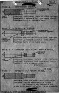 |
On 22 Jun 1943 Gen Carroll assigned secret project number MX-411 to the Lockheed L-1000 gas turbine power plant. [22 Jun 1943 IOM from Brig Gen Carroll to PPL Chief, CO 7-8]
On 5 Jul 1943 MatCmd issued AFP 322189 for the purchase of one Lockheed L-1000 Jet power plant at a cost of $1,352,491. This axial-flow compressor, four-stage turbine engine was to be about 12 feet long and 25" in diameter. There were to be provisions for supplementary tail-pipe fuel injection (afterburning) to achieve maximum thrust. Maximum sea-level static thrust was to be 5,100 lbT with full supplementary fuel injection. Static sea-level thrust at best efficiency was to be 3.500 lbT. [5 Jul 1943 Lockheed Power Plant Proposal L-1000, CO 9]
Nathan Price had learned that Dr. H.C. Cross, Research Metallurgist at the Battelle Institute of Columbus, Ohio sometimes consulted with certain military projects, giving advice on metallurgical applications. Price wanted Dr. Cross to visit Lockheed and confer about L-1000 details. [7 Sep 1943 letter, Hibbard to Col Keirn, CO 13] MatCmd authorized this meeting but prohibited Lockheed from asking about the Halford H-1 or General Electric I-16. [17 Sep 1943 letter, Gen Carroll to Price, CO 18] Dr. Cross wrote MatCmd saying he planned to be at Lockheed on 24 Oct 1943. [27 Sep 1943 letter, Cross to MatCmd, CO 21]
A 10 Sep 1943, letter, Carroll to Development Engineering Branch requesting expedited construction of a Lockheed test building. [CHD 31]
A 13 Sep 1943 Contractor's Proposal references Specification No. 4247 dated 1 Aug 1943 and quotes the following:
| Item | Description | Cost ($) | Fee @ 4% | Total ($) |
|---|---|---|---|---|
| A | Power Plant, 1 ea Lockheed Model L-1000 | 1,081,746 | 43,270 | 1,125,016 |
| B | Maintenance Parts (50% of A) | 194,189 | 7,767 | 201,956 |
| C | Miscellaneous Items (Handbooks, Engineering Data, Models, Export Packing, etc. | |||
| D | Total Fixed Price or Estimated Cost (All Items) | 275,935 | 51,037 | 1,326,972 |
| Delivery of all items was to be by Aug 1945 [CHD 32-35] | ||||
Lockheed learned that some Royal Aircraft Establishment reports had been obtained dealing with British axial compressor analysis, combustion chambers and gas turbines. Lockheed asked to examine these reports [13 Sep 1943 Letter, Hibbard to Col Keirn, CO 17] Gen Carroll notified Lockheed on 22 Sep 1943 that the Royal Aircraft Establishment reports were being compiled for general distribution and a copy would be sent when they became available. [22 Sep Letter, Gen Carroll to Hibbard, CO 20]
On 29 Nov 1943 Gen Carroll wrote Lockheed requesting that brief weekly progress reports be submitted to Col Keirn, with the first report being submitted for the week ending 27 Nov. [CO 23]
Lockheed submitted its first progress report for the week ending 27 Nov 1943 on 8 Dec 1943, enclosing 10 photographs. Additional major L-1000 casting had been received, vane templates had been constructed, final gear set design had been checked by the Gleason Gear Works and a number of smaller parts had been sent for machining. A cascade test rig for testing enlarged scale airfoil inlet and high pressure blower vanes was installed in the Lockheed wind tunnel. Flow similarity tests were continued on mock internal power plant portions using the water test apparatus. A combustion chamber test apparatus had been set up. An electric resistance projection welding technique for attaching blower and turbine blades to drums (U.S. Patent No. 2,448,825 was established using sample parts. Resistance projection welding, or RPW, is a form of resistance welding where electricity, force, and time are concentrated on raised segments (or projections) to join parts. This process has the benefit of forcing the welds to occur in very specific and small locations, minimizing the heat dissipation in the weldment. [8 Dec 1943 progress report, Lockheed to Col Keirn, CO 26] Author's comment: Although the RPW process is fast and accurate, the resulting weld cannot avoid being porous, which makes it vulnerable to low-cycle thermal fatigue and high-cycle vibration fatigue. For compressor and turbine blades, this process, in retrospect, was a very bad idea.
Lockheed submitted its second progress report for the week ending 4 Dec on 8 Dec 1943 enclosing a half-scale proof layout dwg # 300,000 and 8 pictures. The combustion chamber test apparatus had been run to check air pressure drops preparatory to installing the combustion chamber on the power plant. Measurements on a blower airfoil cascade were made in the Lockheed wind tunnel. Construction of a moving airfoil test rig using water for flow similarity was completed; this rig was to be used for detailed blower and turbine vane investigation. The new test building was to be ready for occupancy about 1 Jan 1944. [8 Dec 1943 progress report, Lockheed to Col Keirn, CO 25] Author's note: This is the last progress report for which we have any details; there are scores of additional cover letters, but no actual reports.
On 8 Dec 1943 ,Rear Admiral L.B. Richardson, U.S. Navy Bureau of Aeronautics Assistant Chief wrote MatCmd enclosing Westinghouse 19B installation manual, photographs, a report and expected performance for boster units and main power plant units. Specifications for both unit types were identical; the static thrust was 1,680 lbF, the weight was 695 lb, and the specific fuel consumption was 1.12 lb/hr/lbT. He acknowledged receipt of General Electric TG-100 (T31) and TG-180 (J35) project reports and wondered if these power plants could be made available to the Navy for ground and flight test purposes. He also requested information on the General Electric I-40 and Lockheed L-1000 projects including estimated delivery dates. [CO 27] Brig Gen Carroll responded on 31 Dec 1943 stating that delivery of TG-100 and TG-180 power plants were expected to begin arriving in Jun 1944, but they were all allocated. If Navy wanted one or two, the order needed to be placed immediately. No I-40 or L-1000 data was available but was on order and would be forwarded to Navy when it became available. [CO 32] The Navy requested six TG-100 and two TG-180 engines in a 6 Apr 1944 letter. Navy also stated that additional TG-100 applications were being studied and might result in additional requirements. Navy wanted to know about asymmetrical tail pipe configurations that might be used in conventional tractor installations and stated it might be interested in these. [CO 54] MatCmd replied that the requested units could be made available in March 1945. Gen Carroll stated that an asymmetrical TG-100 tail pipe was under development that would discharge under the fuselage in a TG-100 tractor installation. [19 Apr 1944 letter, Gen Carroll to Rear Adm Richardson, CO 55]
On 28 Dec 1943 Col J.M. Gillespie, PPL Chief requested that Lockheed send 12 L-1000 data folders to Col Keirn for distribution. [28 Dec 1943 letter, CO 30] These were received on 6 Jan 1944. [6 Jan 1944 receipt, CO 39]
On 1 Jan 1944, Brig Gen Carroll wrote Hibbard introducing MatCmd representative Weldon Worth, who had recently joined the MatCmd jet propulsion team. Mr. Worth planned to visit Muroc and Los Angeles in early Jan 1944 and Gen Carroll asked Lockheed to share information about the L-1000 engine, the XP-80 aircraft and similar projects. [CO 33]
A 15 Jan 1944 letter from Col Gillespie directed Hibbard to send copies of all weekly progress reports to date and all future reports to the Commanding General, Army Air Forces in Washington, and to Capt R.C. Schulte, Assistant Chief of the Air Staff, Materiel Maintenance and Distribution. [CO 43]
In a 6 Feb 1946 telegram to Consolidated Vultee, PPL Chief Col R.J. Minty approved request to receive L-1000 data in conjunction with an aircraft preliminary design. [CO 50]
Lockheed intended to withdraw its 15 Mar 1944 letter if this proposal was accepted. [7 Jun 1944 Contract Revision Request, Lockheed to MatCmd, CHD 36-40]
On 16 May 1945 Col Keirn telegraphed Lockheed authorizing L-1000 discussions with Boeing representative Marvin Greenwood. [CO 56]
All data had to be corrected to the NACA standard atmosphere. The curves described had to be plotted with and without supplementary tail pipe burning, and the effect of variable tail pipe nozzle shown. Curve points were to be taken from idle to maximum rpm in 10% increments. [10 Jun 1944 letter from Col Gillespie to the Aircraft Procurement Branch, CO 59]
On 10 Jul 1944 Col Gillespie wrote Lockheed a reminder that the last progress report was from 1 Apr 1944 and requesting the balance of reports be sent expeditiously. He also requested that the reports be sent weekly rather than in groups of 12. [10 Jul 1944 letter, Col Gillespie to Lockheed, CO 60]
In a 29 Aug 1944 letter Hibbard revealed that Lockheed had been led to believe that MatCmd had information regarding the development and test of axial-flow power plants, and went on to request copies. Although the L-1000 design had been complete for some time, information on testing and results of other axial-flow units might help accelerate L-1000 development. [29 Aug 1944 letter, Hibbard to Col Keirn, CO 61] Col Keirn replied that suitable data was being prepared and would be forwarded in the near future [9 Sep 1944 letter, CO 62] Gen Carroll then wrote the British Air Commission seeking its permission to forward six reports to Lockheed. [9 Sep 1944 letter, CO 63] N.S. Muir, Chief of the British Engine Development Section responded on 18 Sep 1944 offering no objection to Lockheed getting the reports and suggested further discussion along with receiving copies of Lockheed reports. He thought such information and interaction would be of considerable mutual benefit. [18 Sep 1944 letter, CO 65] Col Keirn then notified Lockheed that reports were enroot and that the NACA would soon be making further testing information available. [5 Oct 1944 letter, Col Keirn to Lockheed, CO 66]
On 27 May 1945 Clarence L. Johnson and Nathan C. Price visited Gen L.C. Craigie at Wright Field and requested a completion date delay and additional funding. Lockheed had originally planned to use Menasco Manufacturing Company as a subcontractor to the L-1000 project, but Menasco was required by the Army Air Forces to use all its capacity to manufacture landing gear and other parts. This required Lockheed to find other manufacturing facilities in the Los Angeles area and to coordinate the supply of engineering data, material and parts. All of this required additional labor, additional personnel and incurred additional costs. The completed parts produced by the myriad contractors were also often not up to specification. Lockheed also discovered that much more extensive (and expensive) tooling was also required by the wartime workers with their lower skill levels. Additionally, there were problems with acquiring common raw materials, steel casting and special alloys
Lockheed requested that the contract be extended until 1 Jun 1946 and that an additional $607,326 (changed to $666,592 on 26 Jul 1945) be allocated. Since Menasco's Republic P-47 landing gear production was coming to an end, as was Lockheed's P-38 production, skilled engineers and suitable facilities should be available in the future. MatCmd approved Lockheed's request for delivery delay until 1 Jun 1946. The request for additional money started making rounds at MatCmd. [2 Jul 1945 Contract Revision Request, Lockheed to MatCmd, CHD 41-47]
On 29 Jul 1944 Hibbard sent Col Keirn L-1000 progress reports 20 through 34. These had been withheld due to the indeterminate contract state. [29 Jul 1944 letter, Hibbard to Col Keirn, CO 57]
On 28 Aug 1945, Col Keirn wrote Lockheed regarding the failure of the L-1000 high-pressure compressor drum, PN 300651. He suggested the need for a design factor based on actual tests for rotating part design such as the high-pressure drum that failed while undergoing overspeed tests. He requested that Lockheed forward the design calculations showing the stresses at the speed at which the high-pressure drum had failed, along with the strength data and hardness tests on the pieces that had failed. Col Keirn hoped this would help produce the needed design factor. [28 Aug 1945 letter, CO 72]
In a 19 Sep 1945 letter, Lockheed advised Gen Craigie of Lockheed/Menasco L-1000 details. Lockheed and Menasco proposed that the L-1000 project be 100% contracted to Menasco with Lockheed retaining project completion responsibility. Menasco had committed its full facilities and resources to a program of developing and manufacturing power plants. Menasco was an aircraft engine company before WWII and during the war became the predominant hydraulic landing gear source for the western U.S. Menasco concluded that the western aircraft industry called for an adequate power plant source and Menasco was ideally suited to fill that need. John C. Lee, a Menasco director and president, would continue to give this personal attention.
The L-1000 and other engine projects would continue to receive greater concentration from a company specializing in power plant work than in an airframe company. Menasco knew its future depended on successful power plant work. Lockheed could not manufacture the L-1000, whereas Menasco had the equipment, capacity and metallurgical laboratory (one of the country's best), along with "engine conscious" personnel.
For two years, Menasco had accumulated L-1000 prototype manufacturing experience. Menasco's experimental shop had been indoctrinated in the handling of special materials and processes peculiar to gas turbine manufacture. Menasco had been able to increase its L-1000 monthly production hours from 500 to more than 3,000. Menasco could accelerate L-1000 production. As of 1 Sep 1945, 37% of engine components, 20% of tooling and 38% of test equipment has been subcontracted to Menasco. If Menasco could plan on L-1000 concentrated work, it could devote over 6,000 hrs/month, even with the 40-hr week. With a longer work week and some additional specialized equipment then available as surplus, Menasco could increase this number. A speedier L-1000 delivery, with its obvious efficiency and economy in one company was obvious.
Further turbine development, as indicated by Nathan Price's and his L-1000 project group, was physically situated at Menasco. Their first responsibility would be L-1000 completion, but they should also begin planning follow-on turbojets for both piloted and pilotless aircraft. Both Lockheed and Menasco Directors had approved the transfer of the Nathan Price unit to Menasco with continued assurance from Lockheed of its Menasco support as a power plant company. [19 Sep 1945 letter, Lockheed to Brig Gen Craigie, CO 74-76]
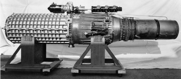 |
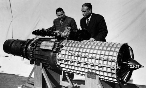 |
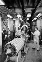 |
| Lockheed XJ37 (NARA) | Lockheed XJ37 with Hall Hibbard (Left) and Nathan Price (Right) (NARA) | |
The L-1000 (XJ37) at Menasco
In a 18 Sep 1945 meeting Lockheed advised MatCmd of its intention to subcontract the remainder of L-1000 work to Menasco. On 26 Sep, a second letter elucidated these plans. The project was then about 2/3 complete, but Lockheed lacked the specialized machine tools necessary for L-1000 fabrication, which had resulted in Lockheed subcontracting about 60% of the work. Menasco at that time had been the subcontractor for about 37% of the engine components, 20% of the tooling and 38% of the test equipment. Termination of war contracts had left Menasco with the capacity to perform all but about 10% of the remaining L-1000 work. Despite subcontracting, Lockheed intended to retain its prime contractor responsibilities for engine performance, and would render Menasco the necessary assistance to ensure the success if its role; Lockheed would retain patent and design rights ownership, and would keep the 2% fee. [26 Sep 1945 letter, Lockheed to MatCmd, CHD 48-50]
On 15 Oct 1945, Brig Gen Craigie requested an additional $300,000, raising the W-535-ac-40690 contract total to $1,492,402, citing limited engine background, difficulty with material acquisition, lower wartime worker skill and wartime tooling shortages as factors contributing to the overrun. [15 Oct 1945 Routing and Record Sheet, CHD 51]
In a 18 Oct 1945 telegram, Col Keirn approved Lockheed's release installation and performance information to Phillip Taylor of Pan American Airlines. [18 Oct 1945 telegram, MatCmd to Lockheed, CO 77]
MatCmd approved Lockheed's plans to subcontract the balance of L-1000 work to Menasco on 22 Oct 1945. [Letter, MatCmd to Lockheed, CHD 52-53]
An additional $300,000 was added to the contract. [15 Nov 1945 Change Order, CHD 54]
On 13 Nov 1945 Lockheed submitted its report on the high-pressure compressor rotor drum failure, "Whirl Tests of Rotor Forgings" dated 4 Oct 1945. [Letter, Lockheed to Col Kerins, CO 80]
On 19 Nov 1945, Hibbard submitted the last L-1000 progress report, No. 101, to MatCmd. Menasco had taken over the development activity and Nathan Price was to submit future progress reports. [Letter, Hibbard to Col Keirns, CO 82]
On 12 Dec 1945, Col P.H. Rockey wrote Price requesting the estimated J37 torque versus speed characteristics, starting characteristics and power takeoff pad data. [CO 85]
In a 4 Feb 1946 telegram, the Consolidated Vultee plan representative sought approval to receive XJ37 data from Menasco. [CO 68]
On 8 Feb 1946 MatCmd granted permission to assemble an accessory section gear grain to serve as a fuel pump drive during testing [8 Feb 1946 letter, CO 87]
On 12 Feb 1946, Lockheed informed MatCmd that it would be unable to deliver by 1 Jun 1946 and requested a delivery extension until 1 Feb 1947. Lockheed estimated that $396,800 would be required to complete the contract and requested the remainder of the $666,592 ($366,592) be allocated. Lockheed blamed the return to the 40-hour work week, production process development difficulty (welding compressor and turbine blades), inability to acquire high-alloy steel castings (requiring increased machine time to make parts from billets), damage to test equipment because of undetected material flaws and tooling development to work with new materials. Menasco had acquired over $100,000 in new machine tools primarily for use with the L-1000 program and was studying Lockheed engine drawings in preparation for production planning. [CHD 55-57]
On 13 Feb 1946 Lockheed again wrote asking for the additional $398,800 it had previously requested, and submitted a revised costed work breakdown structure. [Letter, Lockheed to MatCmd, CHD 58-60]
On 19 Feb 1946, Menasco President John C. Lee wrote Col Keirn informing him that since Jun 1943 Menasco had been working with Lockheed to develop the L-1000 (XJ37) and had used Defense Plant Corporation (DPC) buildings and facilities originally constructed for the L-1000 program. The facilities, commonly known as Lockheed Unit 80, had been transferred to the Reconstruction Finance Corporation (RFC) as Plant Corporation (Plancor) 1193, RCS Project 202B-2. Since about 90% of the remaining L-1000 work was being transferred to Menasco, a formal subcontract was desired and would be submitted around 1 Mar 1946. In the meantime Lockheed transferred its entire L-1000 engineering staff to the Unit 80 facility, where work continued. Menasco asked MatCmd to obtain for Menasco a lease to the Unit 80 property. [CHD 61]
On 20 Feb 1946 Lockheed recommended transferring the Unit 80 property and facilities to Menasco. [Letter, Lockheed to MatCmd, CHD 62-63]
In a 5 Mar 1946 letter, Lockheed substantiated its 13 Feb 1946 request for an additional $398,800. Safe and expeditious XJ37 development required unanticipated and unbudgeted component testing, which it outlined in two attached exhibits.
| Exhibit A: XJ37 Development Test Costs ($) Beyond Original Scope | Exhibit B: Future Required XJ37 Development Test Costs ($) Beyond Original Scope | |||
|---|---|---|---|---|
| 1. Axial flow compressor blading tests | 167,422 | 1. Hydraulic drive tests | 55,790 | |
| 2. Slipper-type bearing tests | 58,031 | 2. Accessories tests | 18,230 | |
| 3. Intercooler 30° segment tests | 19,107 | a. Fuel pump tests with gasoline | 8,100 | |
| 4. Primary combustion chamber tests | 61,006 | b. Speed governor tests | 5,000 | |
| 5. Intermediate turbine combustion chamber tests | 19,031 | c. Fuel control valve tests | 5,130 | |
| 6. Tailpipe combustion tests | 10,505 | 3. Step-wise power plant central portion tests | 312,400 | |
| 7. Fuel pump operation tests | 31,470 | a. With 4 high-compression stages and 1 turbine stage | 171,700 | |
| Total Estimated Exhibit A Costs | 366,592 | b. With 16 high-compression stages and 4 turbine states | 21,200 | |
| c. (b) above with intercooler | 10,100 | |||
| d. (c) above with low-compression stages | 85,200 | |||
| e. (d) above with hydraulic drive | 24,200 | |||
| (Final tests were included in original plan) | ||||
| 4) Endurance testing proposal | 1,140 | |||
| 5) Propeller drive exhaust driven turbine preliminary design | 9,240 | |||
| Total Estimated Exhibit B Costs | 396,800 | |||
[Letter, Lockheed to MatCmd, CHD 64-67]
On 18 Mar 1946, PPL recommend the Unit 80 transfer to Menasco. [MatCmd internal memorandum, CHD 68]
Lockheed provided a cost breakdown of Exhibits A and B was provided; A = $366,592, B = $396,800, total = $763,392 additional funds requested. [25 Mar 1946 letter, Lockheed to MatCmd, CHD 69-76 and 8 Apr 1946 letter from PPL to TSEPE3 Mr. Shaw, CHD 78]
On 28 Mar 1946 Lockheed informed MatCmd that the L-1000 engine program would require about $5,000,000 for preliminary development and small production. [Telegram, Lockheed to MatCmd, CHD 77]
By 8 Apr 1946, the PPL had analyzed Lockheed's 25 Mar requested contract modification and wrote an expanded and refined version of the tasks to be accomplished. This is the version that appears in the 25 Mar discussion above. [8 Apr 1946 letter from PPL to TSEPE3 Mr. Shaw, CHD 78-81]
In a 15 Apr 1946 telegram, Brig Gen Craigie informed Lockheed that $2.5 M for the engine program had been included in the FY 1947 budget and that Lockheed was expected to match that amount from its own funds. The matching clause was marked through by Gen Craigie. [15 Apr 1946 telegram, Brig Gen Craigie to Lockheed, CHD 82]
In a 22 May 1946 telegram the Washington, DC Engineering Division requested: 1) when the XJ37 would first run and 2) when the XJ37 would be sufficiently developed to permit installation in a limited quantity of experimental aircraft. [Telegram from Washington, DC Engineering Division to Gen Craigie, CHD 83] In a 24 May 1946 telegram, Gen Craigie informed Washington that the XJ37 was expected to run in August 1946 and be ready for flight about 18 months later [Telegram, Gen Craigie to Washington Engineering Division, CHD 84]
A 29 May 1946 internal memo from Lt. Col C.D. Glasser, Propulsion Section Chief to Brig Gen A.R. Crawford relayed the XJ37 schedule information Gen Craigie had submitted. Col Glasser was concerned over the unfavorable Westinghouse 24C experience and was keen to get another engine of comparable dimensions and weight. He observed that while the XJ37 schedule did not appear overly optimistic, he urged caution to any firm contemplating designing around the XJ37 as it had several desirable features that might be hard to perfect. Col Glasser nevertheless suggested asking Gen Craigie if the XJ37 development could be accelerated. [CHD 85]
In a 6 Jun 1946 letter, Menasco quoted four sets of unassembled detailed XJ37-1 power plant parts at $1,937,000. Menasco understood that the PPL was to authorize acquisition of raw materials and purchased parts when test reports had been submitted and approved. Menasco requested a letter contract with a 90% partial-payment clause as soon as possible. Menasco estimated the parts sets would be delivered 12, 14, 16 and 17 months from contract receipt. [Letter, Menasco to MatCmd, CHD 86-87]
Authority for Purchase No. 4212886 covering the four parts sets was issued on 6 Jun 1946. The attached engine description specified a turbojet engine with two axial flow compressors, intercooler, annular combustion chamber and multi-stage turbine. Additional fuel-burning means were to be included in the tailpipe. The engine was to produce 5,100 lbT static at sea level, weigh not more than 1,235 lb, and have a 25" diameter. Menasco was to submit monthly progress reports by the 15th of each month and could procure raw material and rough forgings, castings and purchased parts, and design necessary tooling, but no work on the parts was to proceed until Lockheed had submitted test reports that had been approved. This was a sole-source procurement. [6 Jun 1946 Authority for Purchase 421288, CHD 88-91]
On 21 Sep 1946 MatCmd cleared Curtiss-Wright airplane division to receive XJ37 data in order to study power plant configurations for several designs. [CO 94]
On 26 Nov 1946 PPL Chief Col R.J. Minty requested data that would allow development of starters and generators:
Generator –
Lockheed replied on 20 Dec 1946:
Menasco Throws in the Towel
In a 14 Aug 1947 conference between Menasco and MatCmd, Menasco revealed its poor financial position due to poor management until February 1947 and an ineffective accounting system. During the last year Menasco had lost $2.5M dollars on $8M in sales. The new Menasco Executive Vice President and General Manager, Donovan Tyson, had cut $200,000 per month in payroll costs. Its bills were being paid currently, but bills incurred before 1 Jul 1947 amounted to $500,000 to $700,000 among over 60 creditors, which was being liquidated at 10% per month. Tyson expected the company to again make money during the next few months, putting it in the position to ask for a Government-guaranteed loan extension on 7 Sep and ultimately loans from private concerns. Menasco's strut business had picked up and it was assembling washing machines from parts kits fabricated elsewhere.
Because of the forgoing, Menasco was in no position to undertake additional obligations connected with ramjet and gas turbine development because it could not get the operating capital to sustain such endeavors while it waited for government reimbursement. Tyson suggested a three-way arrangement between Menasco, Lockheed and some other engine company. Several other business and facility scenarios were discussed, but none got much traction. Col Minty said that MatCmd definitely wanted the L-1000 program to continue under Price's leadership. Lockheed was preparing a proposal that MatCmd was to hear on 9 Sep 1947, so Col Minty postponed a decision until after that. [10 Sep 1947 Memorandum Report TSEPP-506-220, P361971]
On 9 Sep 1947 the Airo Engineering Company of Wayzata, Minnesota requested XJ37 information for a runway snow removal application. MatCmd refused. [CO 101]
On 9 Sep 1947 Lockheed met with MatCmd at Wright Field to discuss XJ37 disposition. Lockheed stated that it was an airframe manufacturer that had to emphasize that business. While an engine project had impacted Lockheed's principal business, Lockheed did not want to leave the impression it had "run out" on the engine project, which would reflect upon Lockheed's integrity or cause the Army to feel it had been let down. Lockheed outlined three avenues for the XJ37: let Menasco continue as at present; let Lockheed re-assume project responsibility; let an organization with superior experience, facilities and capabilities take the project over. Lockheed pointed out that were it to re-assume project responsibility it would have to enlarge its facilities and that its post-war financial position was not strong and obtaining money would be a problem. Lockheed wondered if it, inexperienced in engine development, could give the Army a good product. Lockheed hoped to see some financial return from the XJ37 if it became valuable, but would not let patent and license issues obstruct the XJ37's future. Col Minty observed that any outcome would result in a considerable schedule delay. [24 Sep 1947 Memorandum Report TSEPP-506-226, P361985]
This memorandum was distributed to Allison, General Electric, Packard, Pratt & Whitney, Wright, Lockheed and Menasco. [18 Sep 1947 Memorandum Report TSEPP-506-223, P361980]
On 15 Sep 1947 the PPL held a conference to interest established aircraft engine companies in assuming development and production of the Menasco XJ37, a turboprop version and possibly the XRJ37 ramjet engine. In addition to PPL, Allison, General Electric, Packard, Pratt & Whitney, Wright Aero, Lockheed and Menasco representatives attended. PPL Chief Col Minty gave an XJ37 overview with dimensions, ratings, characteristics, outstanding features, and the project's history and objectives. Col Minty also provided information on the proposed XJ37 turboprop version and the XRJ37 ramjet. Price discussed the engineering status and Lockheed stated its position on patent rights, which amounted to doing whatever was necessary to see the project to completion. Visits were arranged for Price to discuss engineering details and all companies agreed to send engineers to Menasco on 29 Sep 1947 to examine the engine and discuss engineering details. A patent right discussion was to be held at Lockheed on 30 Sep. PPL was to furnish an XJ37 thermodynamic analysis and Lockheed was to send a general statement of license rights before its visit.
MatCmd recommended that a contract be negotiated with Wright to evaluate the J37 and make available to industry its findings, excluding any subsequent proprietary engine changes. At the conclusion of this activity a further decision would be made as to the type and size engine desirable at that time.
MatCmd was compelled to terminate J37 development at Menasco because the company lacked facilities and suffered from financial and management problems. In selecting the new developer, MatCmd placed great emphasis on development test facilities, followed by the developer's willingness to absorb Menasco personnel associated with the project.
| Grades | ||||
|---|---|---|---|---|
| Evaluation Criteria | Maximum | Wright | Packard | Ranger |
| Test Facilities | 400 | 300 | 150 | 25 |
| Manufacturing Facilities | 200 | 150 | 50 | 100 |
| Effect on Existing Contracts | 100 | 75 | 75 | 50 |
| Problem Approach | 100 | 75 | 90 | 60 |
| Menasco Personnel | 200 | 100 | 150 | 175 |
| Total | 1,000 | 700 | 515 | 410 |
[1 Dec 1947 Memorandum Report TSSEP-518-374, P362441]
 |
 |
 |
 |
 |
| Walk Around (Author) | ||||
Wright Aeronautical Takes Over XJ37 Development
Sometime in 1948, XJ37 production was terminated at Menasco and transferred to Wright Aeronautical where, presumably, development continued. [Undated cross reference sheet, CO 106] We know almost nothing about what happened to the engine after Wright took it over. No available correspondence, reports or memoranda address J37 development. According to St. Peters, Wright delivered the last three XJ37s (presumably built from Menasco parts) to the Air Force Arnold Engineering Develeopment Center in Tullahoma, Tennessee in July 1953. The test data and project files were also delivered and made available to American gas turbine manufacturers at no cost. [StPeters 103]
One thing that almost certainly DID NOT happen at Wright is that the J37 became the Wright T35, as many have asserted, but without attribution. With either a two- or three-stage centrifugal compressor, the T35 was a much different, much larger (59" as opposed to 25" diameter), and much heavier (nearly 6,000 lb!) engine [ModDesig2]. According to Douglas Culy’s detailed XT35 paper, taken largely from primary sources, Wright started to study it in 1942, got a development contract on 22 Nov 1944, and ran the engine on 24 Jun 1946, nearly a year and a half before the XJ37 became available. The author is eager to learn what, if anything, happed with the XJ37 at Wright
Conclusion
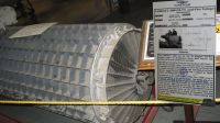
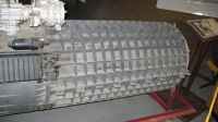
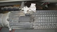
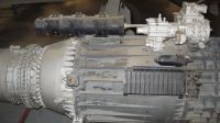
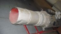
Unfortunately, we have no substantiated XJ37 performance data from actual tests. One source says it only produced only 2,200 lbT, while another says 2,650 (both a far cry from the over 5,000 lbT promised) and James St. Peters says it was never self-sustaining; no source provides any attribution for these data. Similarly, we do not know the size, weight, fuel consumption, actual configuration, etc. One example remains and is on display at the Planes of Fame Museum in Chino, California, but even this artifact has no history. It is a true shame that America’s first jet engine has fallen into such obscurity. One can only hope that some lucky researcher will someday find more documentation on this engine.
References
[CHS] Case History of L-1000 (XJ37-1) Jet Propulsion Engine, Summary. (Wright Patterson AFB, Ohio: Historical Division Intelligence, T-2, Air Force Historical Research Agency 202.2-46, Jun 1946).
[CHB] Case History of L-1000 (XJ37-1) Jet Propulsion Engine, Brief. (Wright Patterson AFB, Ohio: Historical Division Intelligence, T-2, Air Force Historical Research Agency 202.2-46, Jun 1946).
[CHD] Case History of L-1000 (XJ37-1) Jet Propulsion Engine, Documents. (Wright Patterson AFB, Ohio: Historical Division Intelligence, T-2, Air Force Historical Research Agency 202.2-46, Jun 1946).
[CO] Correspondence File, 452.8 - Turbojet J-37 - Lockheed Aircraft. 1943-45-46-47. USNARA Record Group 342 RD3844.
[ModDesig1] Model Designations of U.S.A.F. Aircraft Engines (Wright Patterson AFB, Ohio: Materiel Command, 1 Jan 1950, Section II, Page 6)
[ModDesig2] Model Designations of U.S.A.F. Aircraft Engines (Wright Patterson AFB, Ohio: Materiel Command, 1 Jan 1950, Section III, Page 1)
[P361980] 18 Sep 1947 Memorandum Report TSEPP-506-223. Conference Between Menasco Manufacturing Company and Air Materiel Command on XJ37. USNARA RG342 P361980.
[P361982] 22 Sep 1947 Memorandum Report TSEPP-506-224. Conference Held at Wright Field Between Representatives of Air Materiel Command and Several Engine Companies. USNARA RG342 P361982.
[P361985] 24 Sep 1947 Memorandum Report TSEPP-506-226. Conference with Representatives of Lockheed Aircraft Corporation on the XJ37 Turbojet Engine. USNARA RG342 P361985
[P362450] 25 Sep 1947 Memorandum Report TSSEP-506-228. Menasco XJ37 Turbojet Engine Development. USNARA RG342 P362450.
[P362441] 1 Dec 1947 Memorandum Report TSSEP-518-374. Evaluation of J37 Proposals. USNARA RG342 P362441.
Schlaifer, Robert. Development of Aircraft Engines (Boston, Massachusetts: Harvard University, 1950)
St. Peter, James. The History of Aircraft Gas Turbine Engine Development in the United States: a Tradition of Excellence (Atlanta, Georgia: International Gas Turbine Institute of the American Society of Mechanical Engineers, 1999). This book has several good images of the XJ37 low-pressure compressor, high-pressure compressor, power takeoff, combustor, and turbine.
Acknowledgements