

Rolls-Royce Conway, Part 1
Overview, Compressor, Combustion, Turbine
Compiled by Kimble D. McCutcheon
Published 12 Apr 2016; Revised 24 Apr 2016
Table of Contents
Rolls-Royce Conway Part 1: Overview, Compressor, Combustion, Turbine
Rolls-Royce Conway Part 2: Accessory Drives, Fuel System
Rolls-Royce Conway Part 3: Oil, Starting and Air Systems
Rolls-Royce Conway Part 4: Operation
Rolls-Royce Conway Part 5: Bomber Installations
Rolls-Royce Conway Part 6: Transport Installations
Background
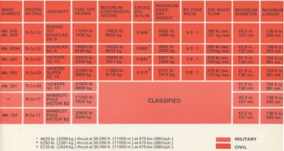
The Conway was initially developed to power the Handley Page Victor B.2. Design started in Oct 1947 and the first engine ran in Aug 1952, producing 9,500 lbT. Development continued until first flight, where a thrust of 13,000 lbT was achieved during Aug 1955. The Conway 12 entered service in April 1960 with a rating of 17,500 lbT. Further refinement led to the Conway 42, which entered service in April 1964 with a rating of 20,370 lbT, and the Conway 43, which entered service in Apr 1965 with a rating of 21,800 lbT.
Because of its historical significance as the world's first turbofan, we shall explore the Conway will in detail within the following pages. Much of this will refer to the Conway Mk 201, but the concepts are applicable across the Conway series.
 |
 |
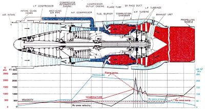 |
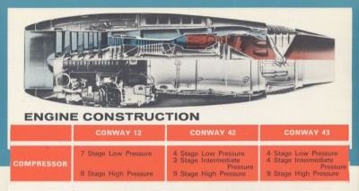
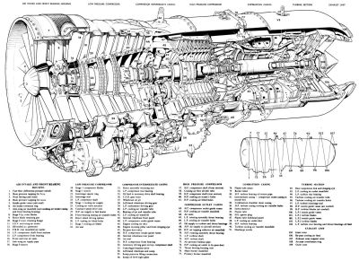
| Conway Models, Specifications and Applications | Conway Construction Details | Conway Gas Flow |
 |
 |
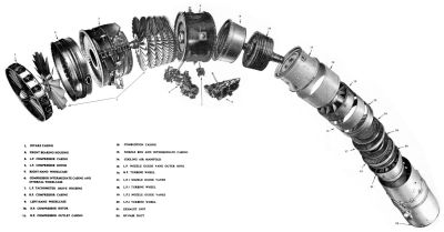 |
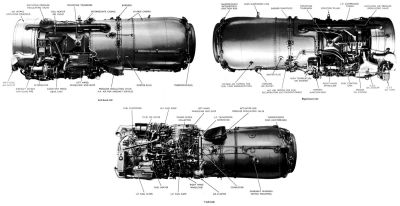
| Conway Views | Conway Cutaway | Conway Exploded |
Overview
The Conway is two-spool axial-flow turbofan that bypasses about 30% of the total airflow around the hot engine core, raising its overall efficiency as compared to pure turbojets. Such engines are now classified as low-bypass turbofans as compared to high-bypass turbofans, which bypass more than 90% of the airflow around the core. The Mk 201 features a seven-stage low pressure (LP) compressor driven by a two-stage LP turbine, and a nine-stage high pressure (HP) compressor driven by a single-stage HP turbine.
Air drawn through intake guide vanes by the first stage of LP compressor blades is swept through all seven stages, each increasing its pressure. Upon exiting the LP compressor, the airflow divides with a portion entering the bypass duct and the remainder being further compressed by the HP compressor. Air from the HP compressor is delivered to combustion chambers where fuel is mixed and ignited. Addition of heat causes the air to expand and its velocity to increase. It then flows through the turbine sections, which extract the energy necessary to drive the LP and HP compressors, and finally joins the bypassed air to be ejected into the atmosphere.
Some LP air is used to pressurize oil seals and cool compressor bearings. Bypass air cools the turbine bearings. HP turbine wheel, blades, and HP nozzle guide vanes are cooled by HP air from the inner combustion chamber casing. Some HP air, tapped from the HP compressor outlet, is used to prevent ice formation in the engine nose fairing and intake guide vanes. The HP compressor shaft drives a number of accessories via one internal and two external wheelcases. A self-contained oil system using gear-type pressure and scavenge pumps circulates synthetic oil through all rotating shaft bearings and gears. The oil is cooled via a fuel-cooled oil cooler. Bearing oil leakage is prevented by air-pressurized continuous grooves and labyrinth seals. An air turbine starter rotates the HP compressor shaft for starting. Two mounting trunnions located on the engine sides transmit thrust loads to the aircraft. In addition two lifting eyes on the engine top serve to absorb side loads and suspend the engine rear.
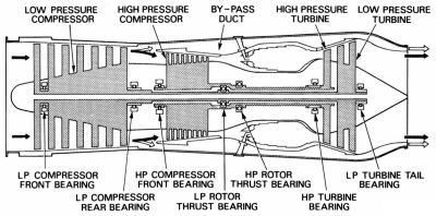 |
| Conway Mk 201 Schematic |
Powered by phpBB © 2001, 2005 phpBB Group |