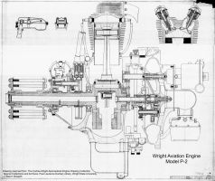
Wright Aviation Engine, Model P-2
(Large Image in the Members' Section)
Wright Aviation Engine, Model P-2 CAD Models
P-2A, P-2B, P-2C
by John Riend
Published 28 Jan 2024; Revised 31 Oct 2025
|
Wright Aviation Engine, Model P-2 (Large Image in the Members' Section) |
Ninety-eight years ago, Wright engineers were hard at work on the latest, greatest air-cooled radial engines. The history on “most of” Wright’s early engine progress has been covered by others, but there are still a few stories to be found. In this case, Wright’s work on the models P-1 and P-2 Cyclones that provided the foundational knowledge for large air-cooled radial engines that progressed into the R-1750 and later R-1820 Cyclones. |
 |
25 Jan 2024
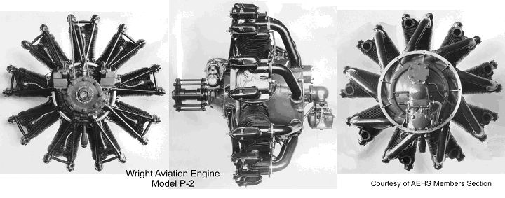
Other than basic specifications, there is very little readily-available technical information or drawings for either engine. Some excellent P-1 photographs and test data exist at the National Air and Space Museum (NASM) (1) and a few P-2 photographs are in the AHES (members section) and NASM (1). There are lots of accounts in the aviation literature on the progress of these engines but that is about it.
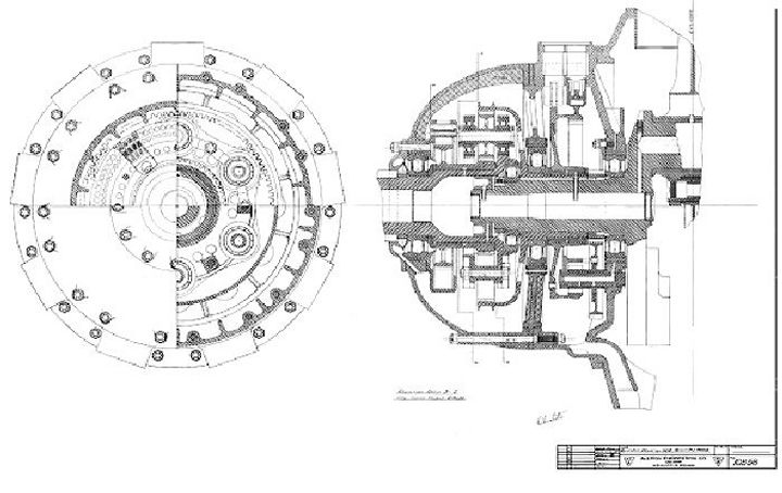
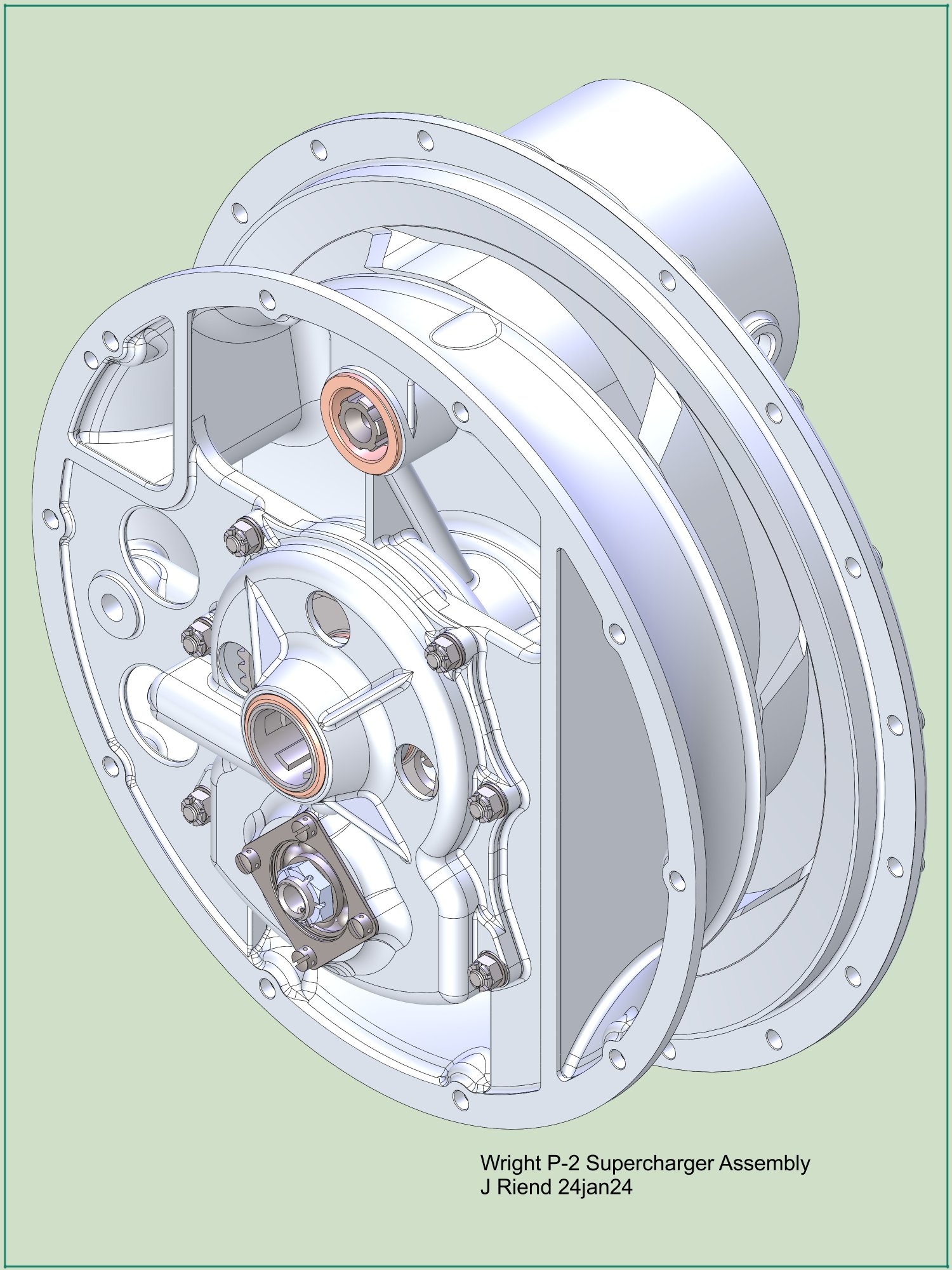
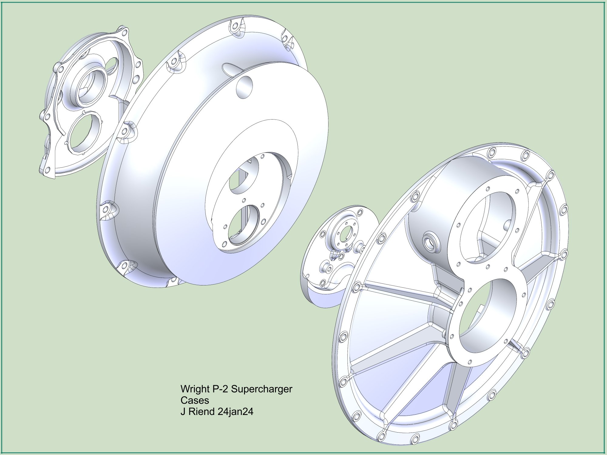
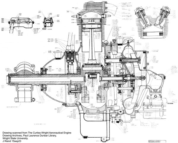
Over several years of research in the Wright Aeronautical Division (WAD) Engine Drawing Archive, I have complied a collection of drawings on Wright’s early air-cooled radial engines (J Series & others), including many on the P-1 and P-2 engines. Unfortunately, many of the key drawings were either not filmed or are missing (bad microfilm, etc.), which makes it difficult to accurately recreate a 3D model of a complete engine. In the case of the P-2, I was able to find sufficient drawings to create an approximate reconstruction of the P-2 supercharger assembly.
Based on the design similarity between the R-1200 Simoon and the P-2, I decided to take a closer look at modeling the P-2, even though there is no crankcase drawing available. Comparing the two engine’s Bills of Material (BOM) shows they used many of the same components, and focusing on the supercharger assembly, both engines used essentially the same components (with some minor variations). Based on that finding I decided my first project on any of the P-1, P-2 and R-1200 engines would be to build an approximate 3D model of the P-2 supercharger assembly.
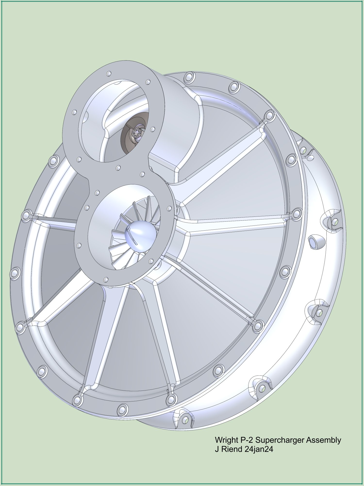
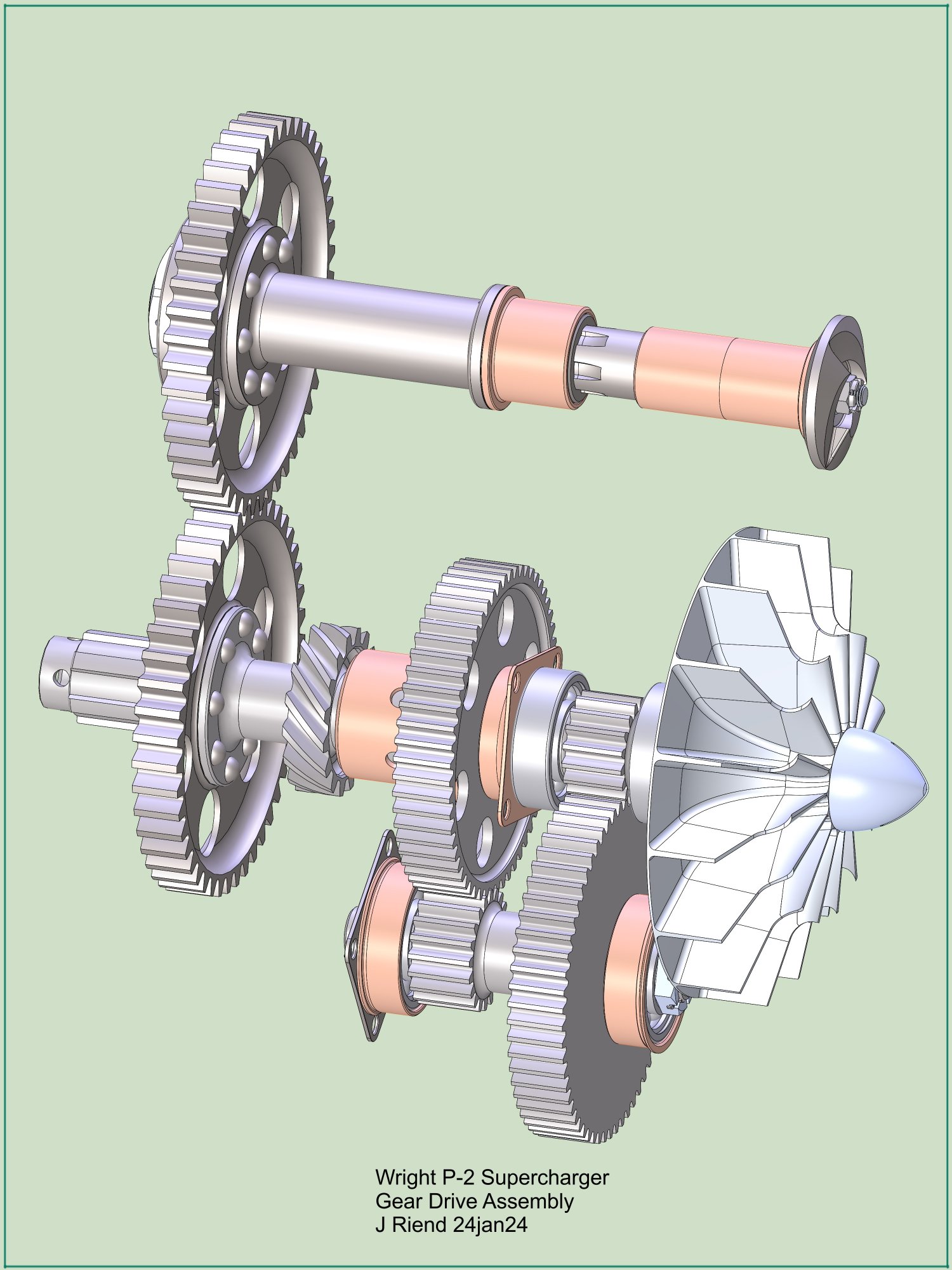
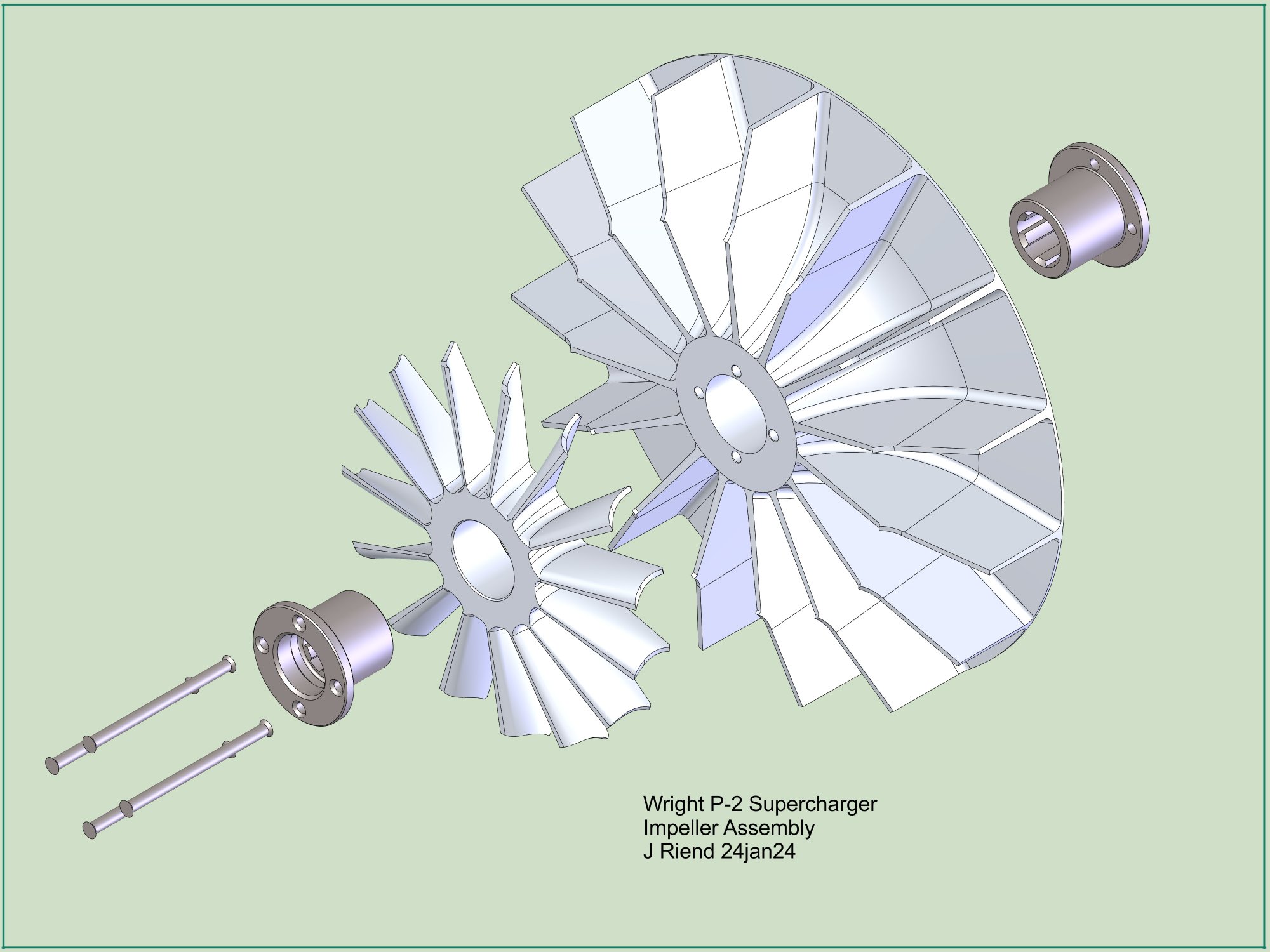
The drawings for the P-2 supercharger components are reasonably legible but have a number of dimensional discrepancies that would have been corrected if the engine had gone into production. There was no drawing for the P-2 impeller, but with outline dimensions from the R-1200 impeller and inducer drawing for the P-2 it was easy to reverse engineer an approximation to the P-2 impeller. Something noteworthy here is the terminology being used at the time. Wright and presumably General Electric (who manufactured the unit for them) used the term “supercharger air scoop” for what’s currently called an inducer.
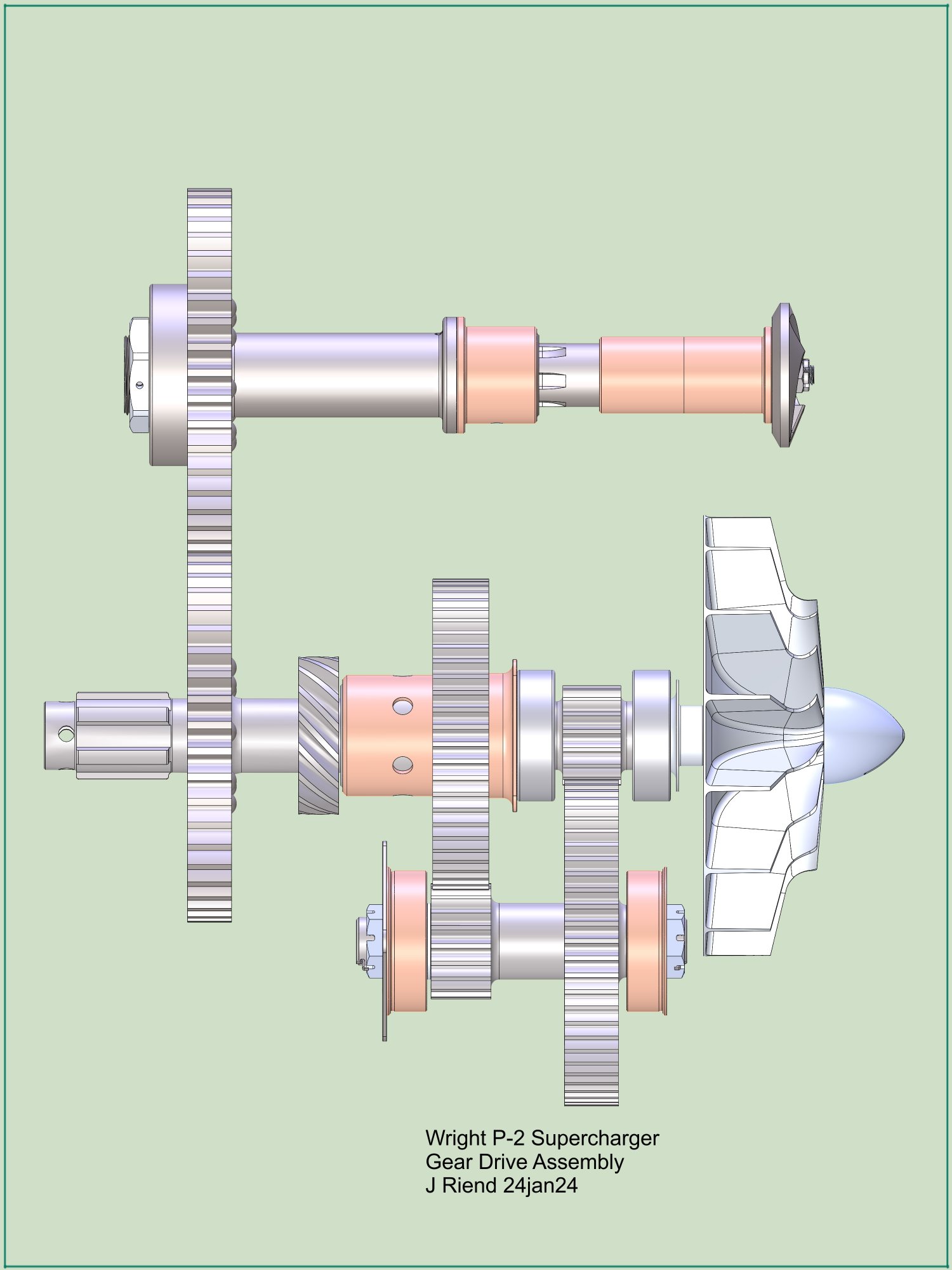
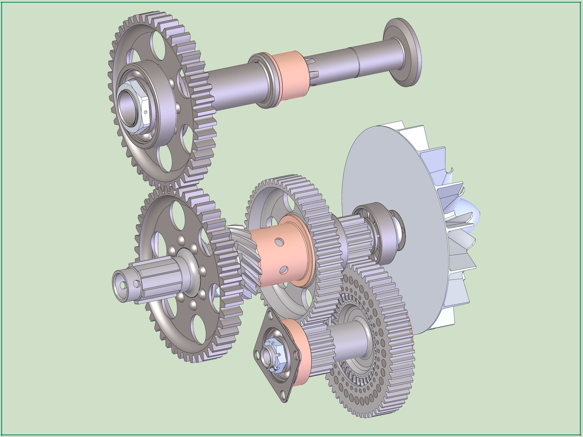
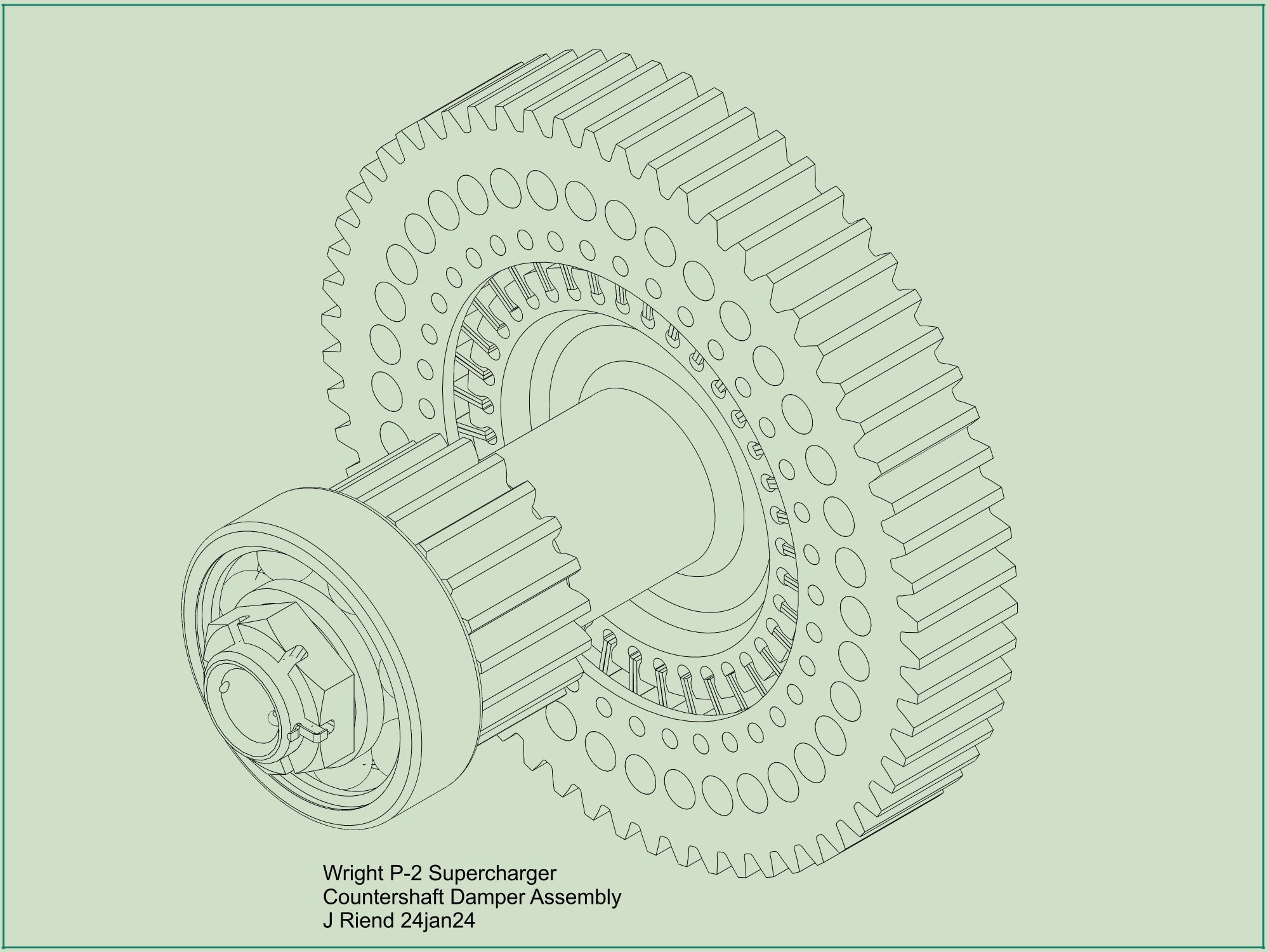
Another item not explicitly covered on the P-2 drawings is a vibration damping coupling used in the propeller reduction gearing (shown below) and supercharger drive gears. There was a P-2 supercharger section drawing stating the gear coupling was made by Allison Engineering. I asked Kim McCutcheon if he would contact his friend at Allison and ask if they had any record of the P-2 coupling project. John Leonard promptly replied with several drawings of spring couplings projects from his plans book Allison Drawings, 1919 - 1943 (2).
 |
Then it was a simple task to track down the patent issued to Norman Gilman at Allison on the spring coupling design (3). Using the few dimensions that I did have, along with the Allison illustrations, I constructed an approximation to what Wright might have used on the P-2 for the spring coupling on their supercharger drive mechanism.
If anyone has any technical information on the Wright P-1, P-2 or R-1200 engines that they would like to share, or has comments or suggestions on my 3D models, please contact me via the AEHS webmaster link at the bottom of this page.
Wright Aviation Engine, Model P-2A
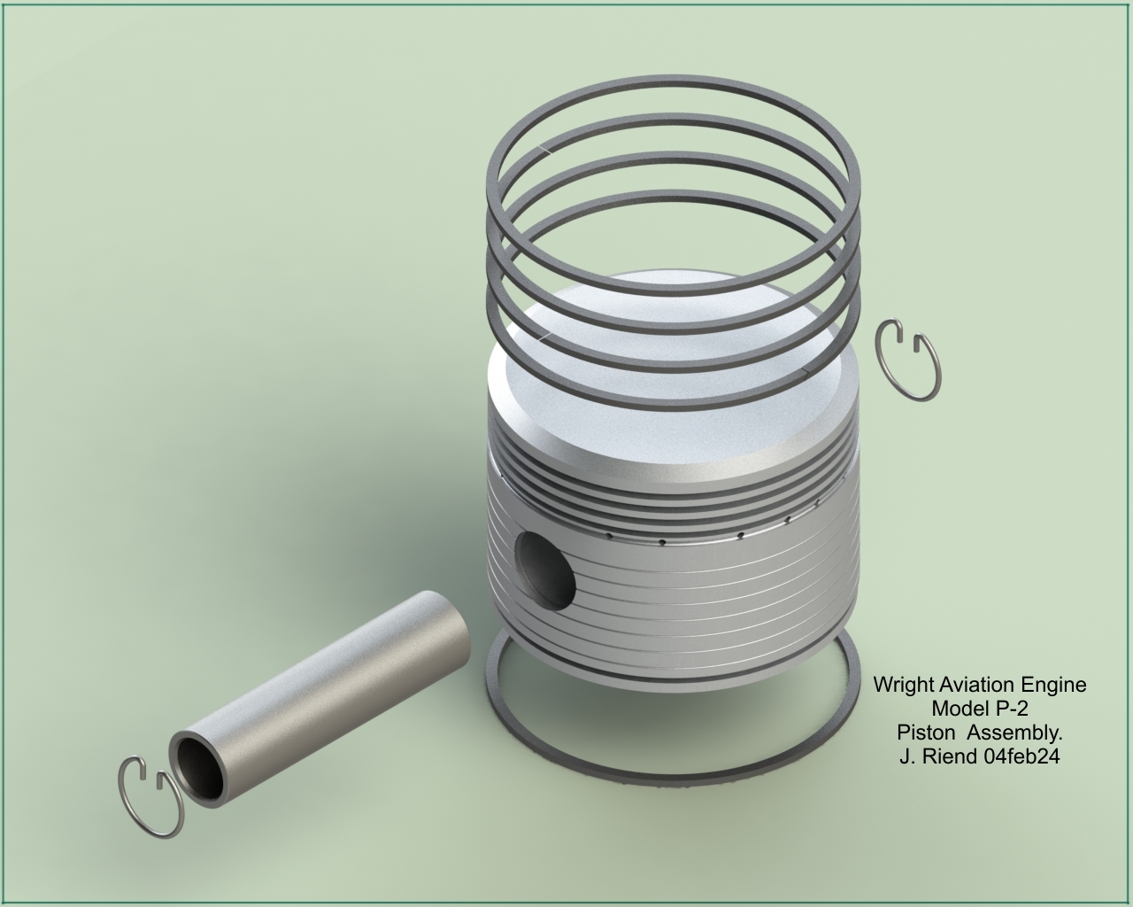
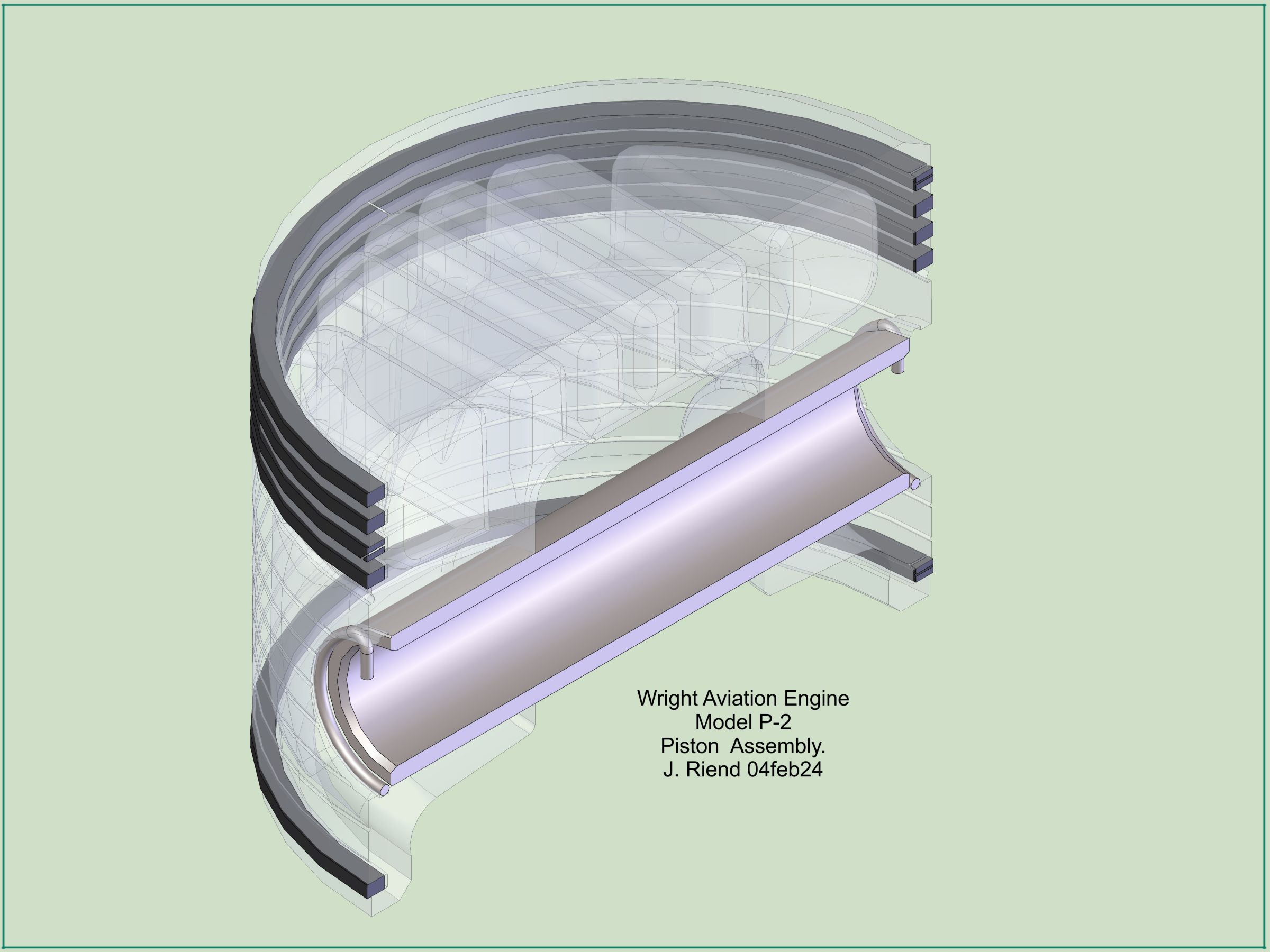
| Complete-Engine Views | Connecting Rods | Crankshaft | Piston | Supercharger |
 |
 |
 |
 |
 |
| Front | Left | Aft | Top | Bottom |
 |
 |
 |
 |
| Top Right Aft | Top Left Front | Exploded View | Drawings (Members' Section) |
 |
 |
|
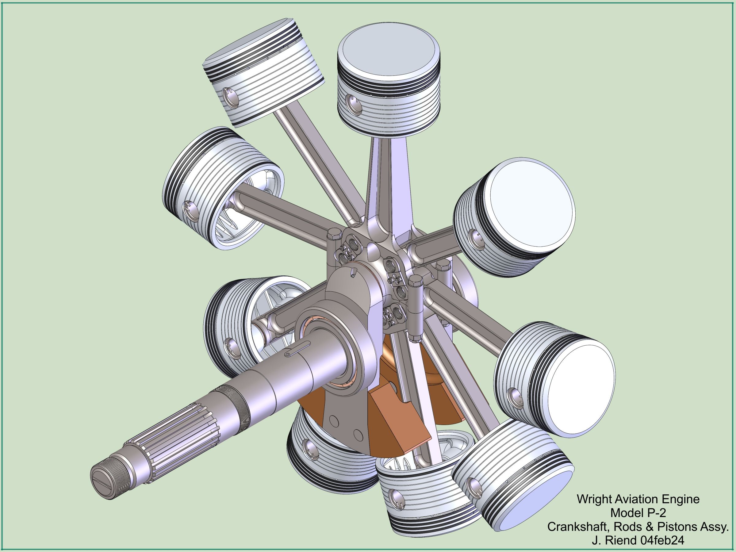
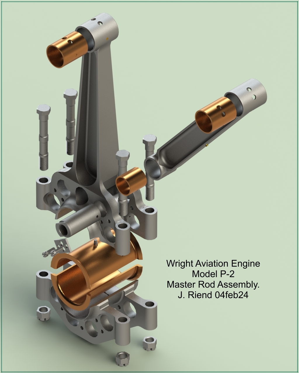
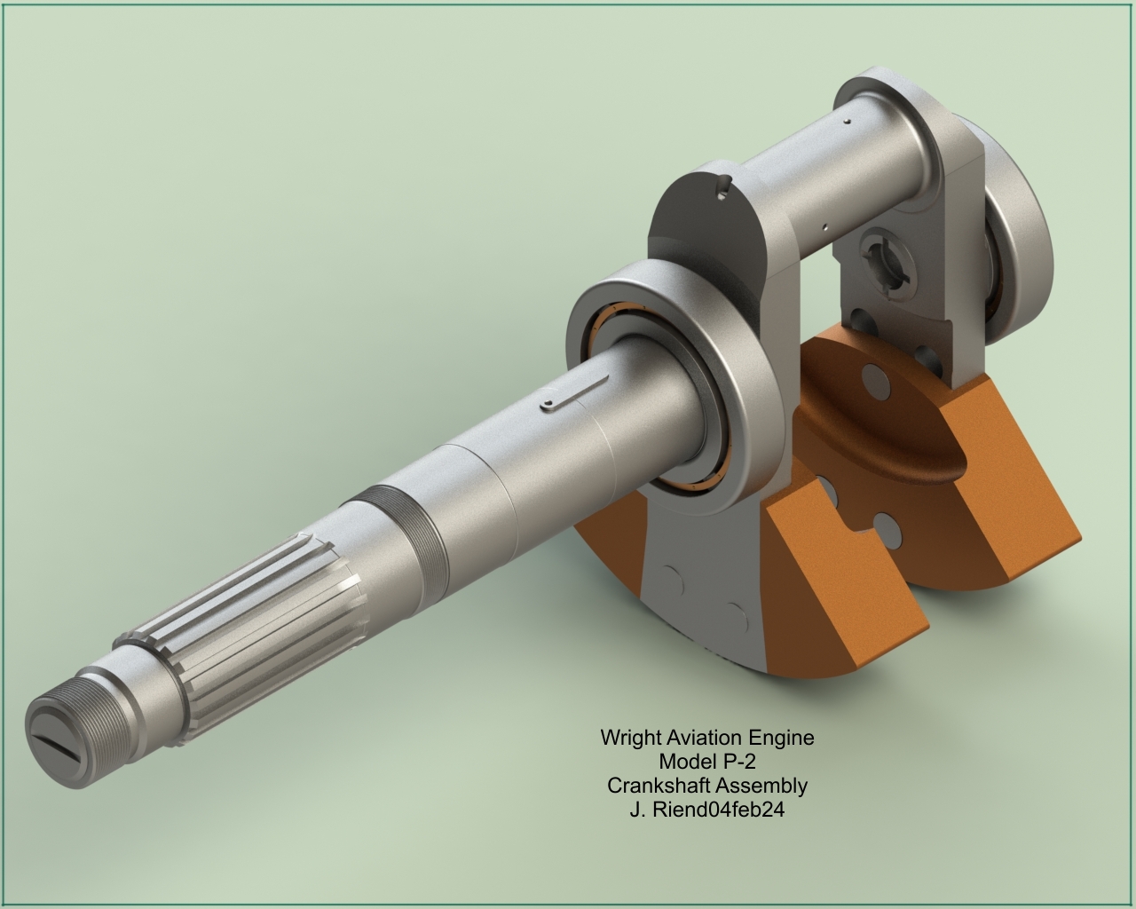
| Crankshaft, Master Rod, Articulated Rods, Pistons | Master Rod | |
 |
 |
 |
 |
 |
 |
 |
 |
 |
 |
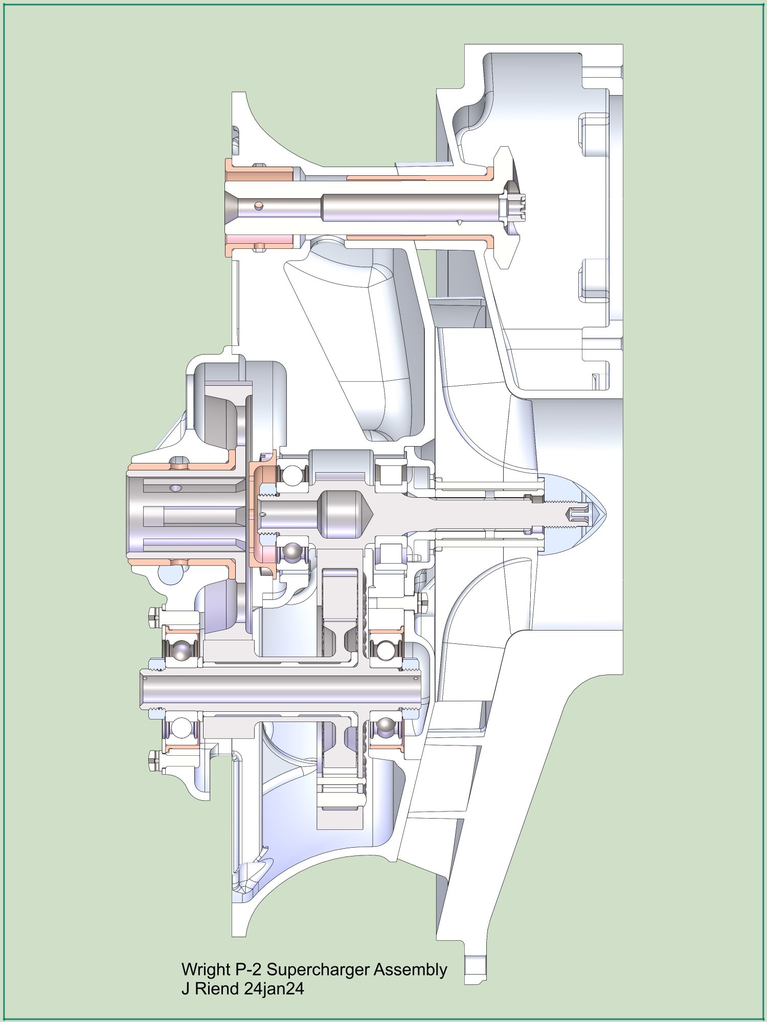
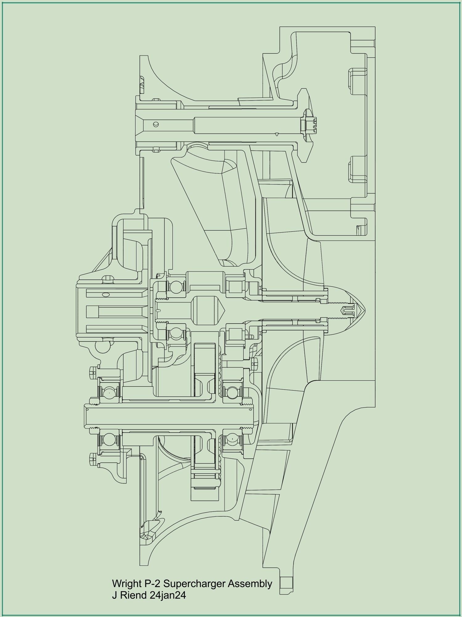
| Supercharger Assembly | ||||
 |
 |
 |
 |
 |
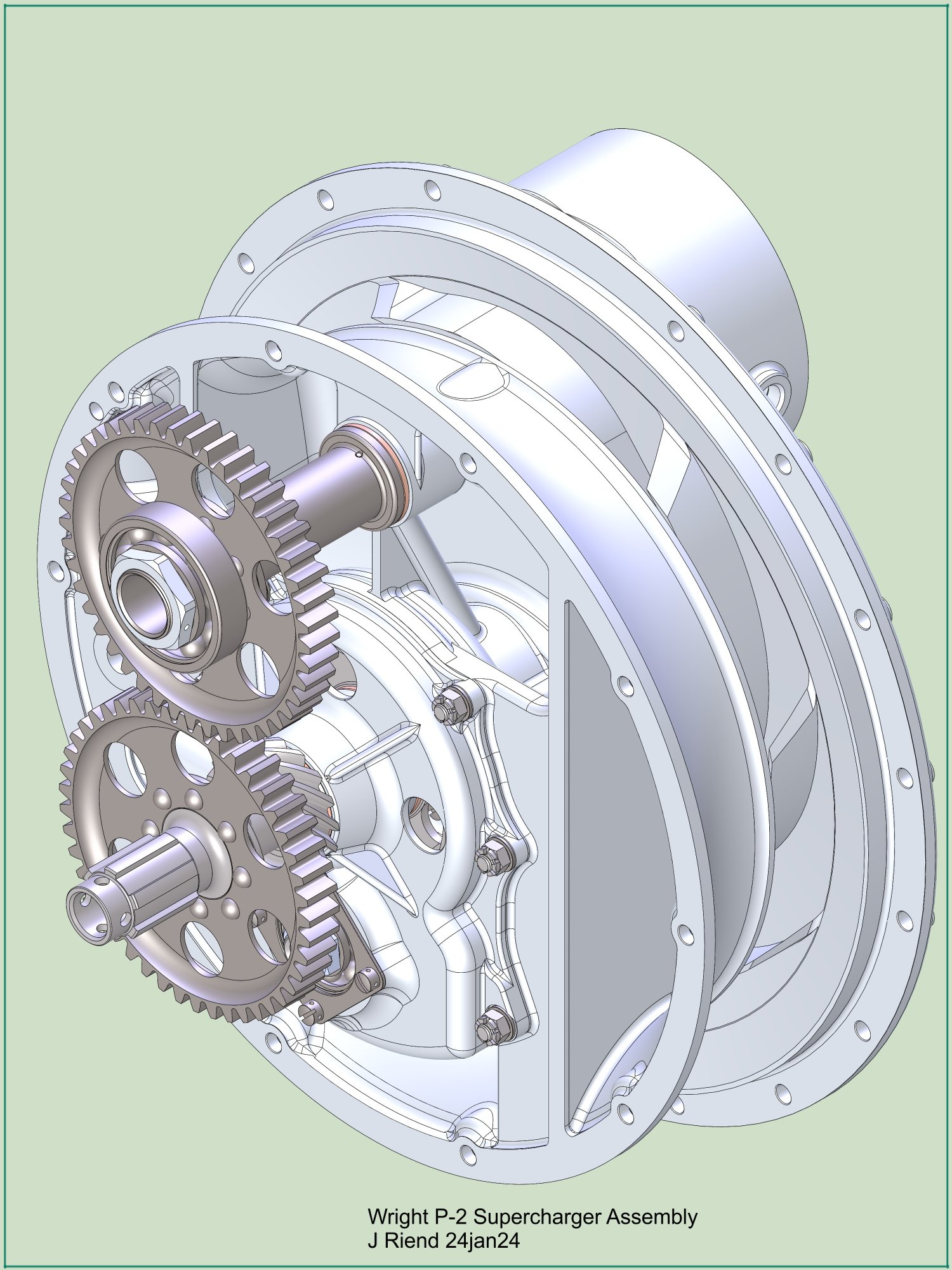
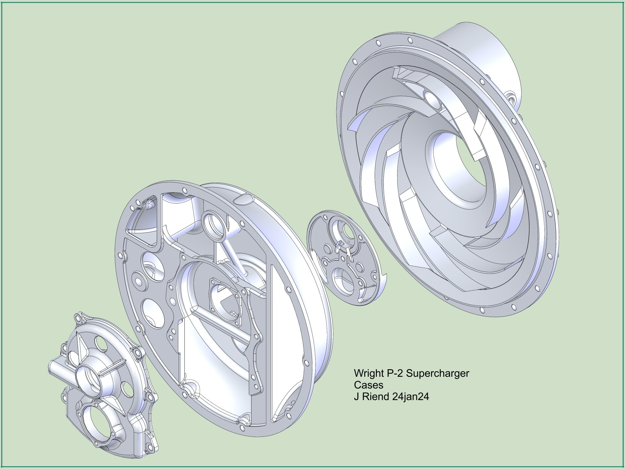
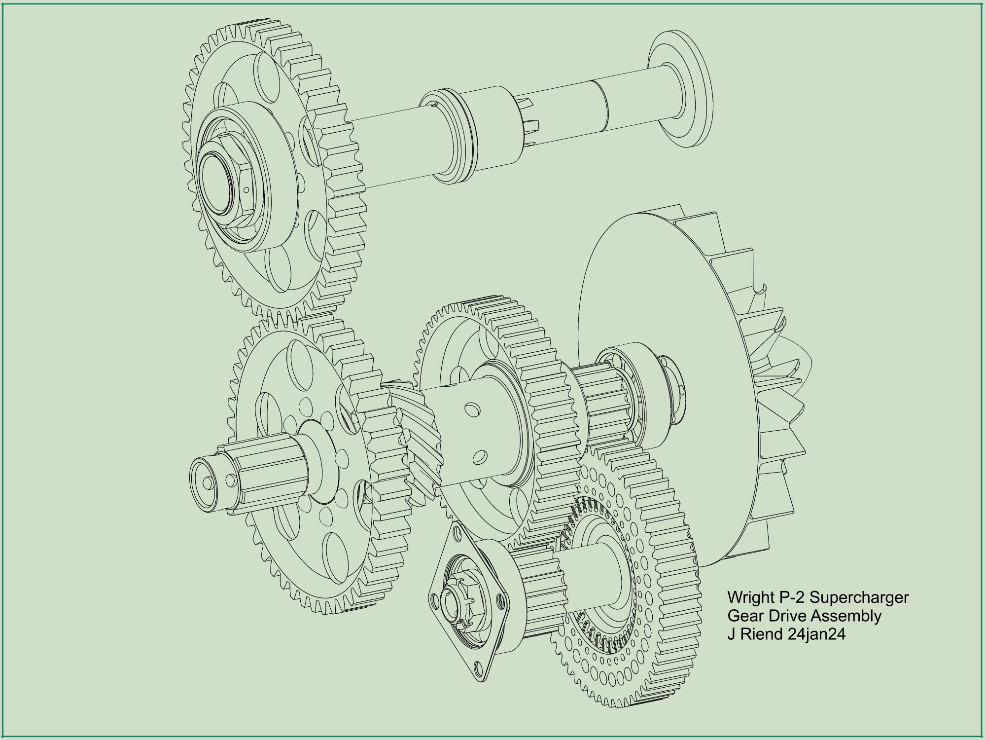
| Supercharger Case | Supercharger Gear Drive | |||
 |
 |
 |
||
| Supercharger Gear Drive | Supercharger Impeller Assembly | Countershaft Damper Assembly | ||
08 Feb 2025
Since completing the P-2 supercharger project I continued my research in the WAD Archive and have identified several new (to me) P-2 engine assembly drawings that provided additional Part Numbers (P/Ns). for some of the missing components. These new P/Ns. allowed me to confirm that several components were not filmed and some were on microfilm rolls that deteriorated and were destroyed due to vinegar syndrome. The three P-2 engine assembly drawings (13410, 13450, & 13705) are among the only available documentation that show the progression of the P-2 Cyclone as it evolved into the future R-1750.
Several documents (4, 5, 5a) show that there were 12 P-2 engines built for the Navy and that 2 of them were replaced with an improved P-2 engine equipped with a 2:1 ratio reduction gear.
After being thrust into building air-cooled engines by the Air Corps and Navy, Wright realized air-cooled engines had a promising future in large military and commercial aircraft. Seeing the potential for sales in commercial aviation, Wright devoted much more engineering effort to the development of the P-2 and R-1750. Wright was also motivated because of their top engineering people running off and forming Pratt & Whitney Aircraft to compete against them. The P-2 engine evolved into the R-1750, and was built in three successive revisions as indicated in their respective assembly drawings:
The original P-2 (P-2A) engine, a continuation of the P-1 project, was a scaled-up version of the Whirlwind engine that included an engine driven supercharger designed by GE. It had (Heron designed?) aluminum cylinder heads with integral cylinder fins and screwed-in flanged liners.
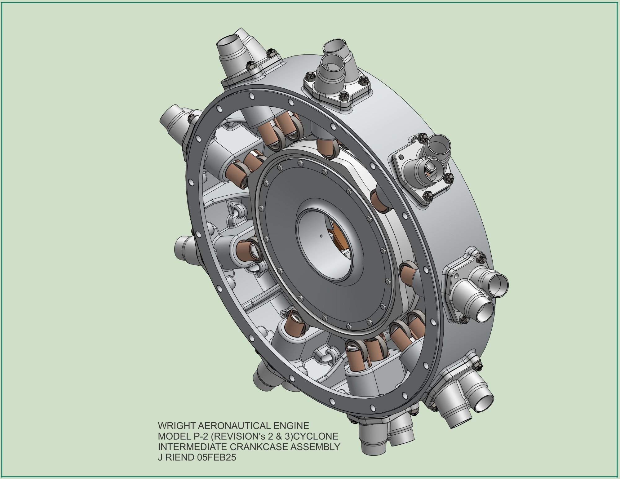
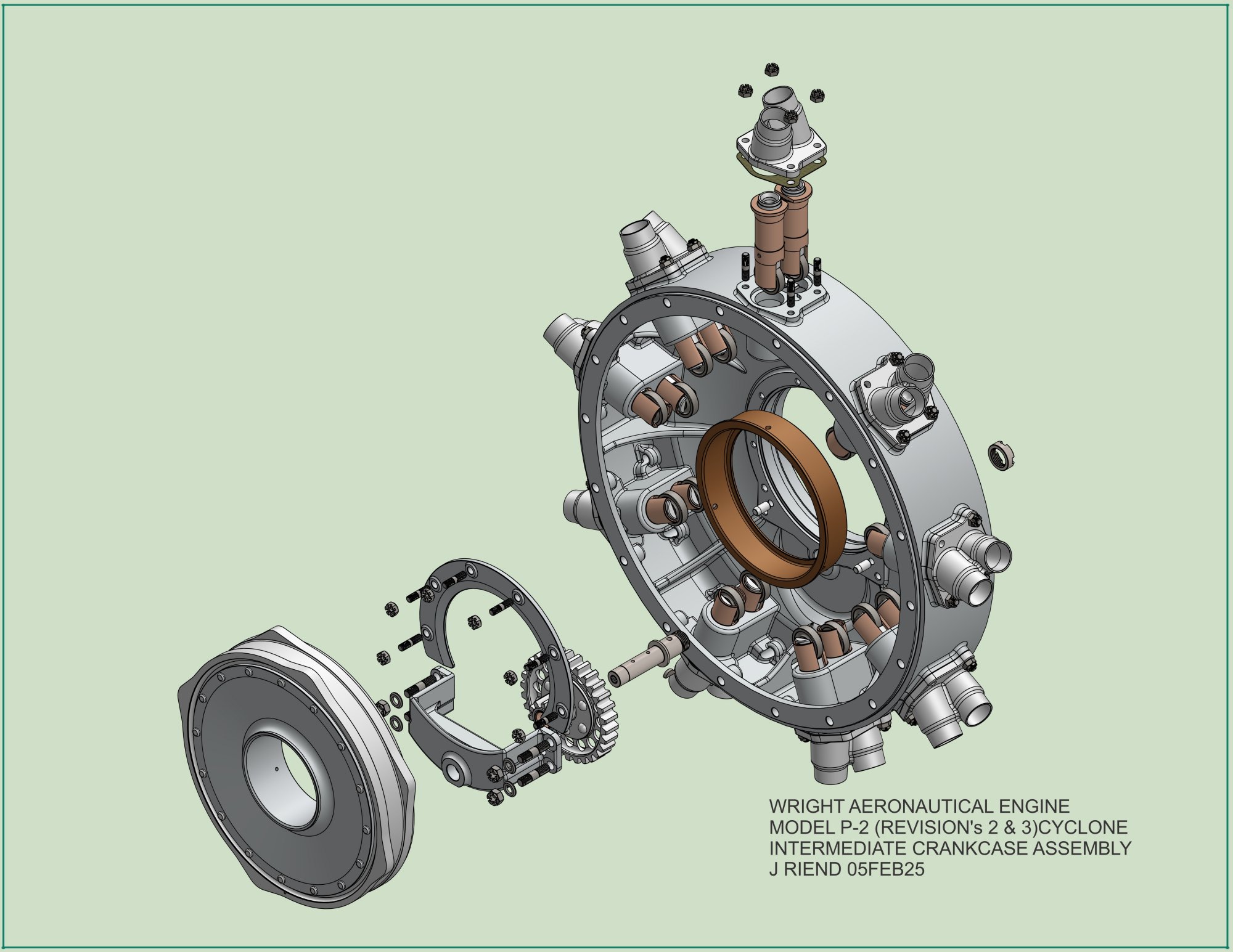
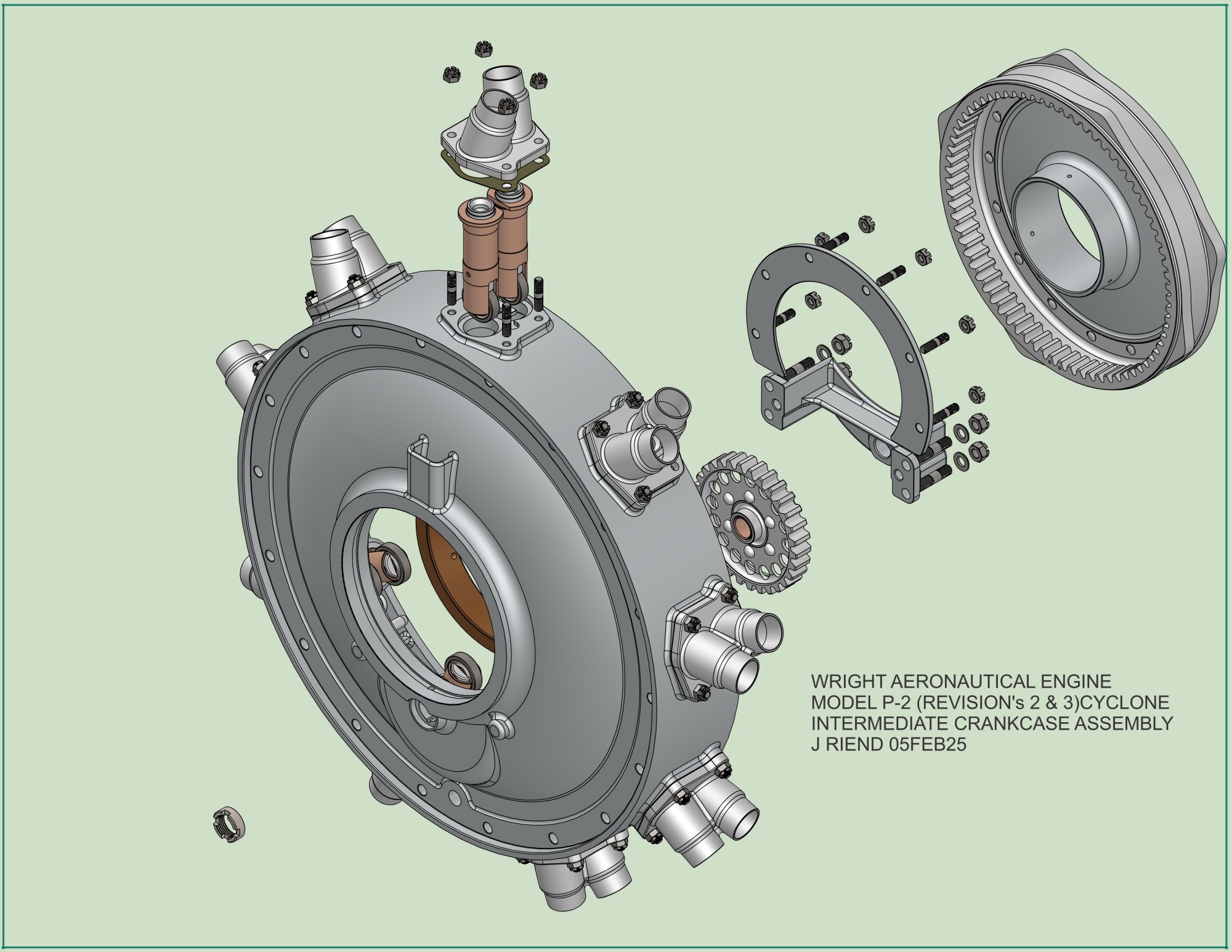
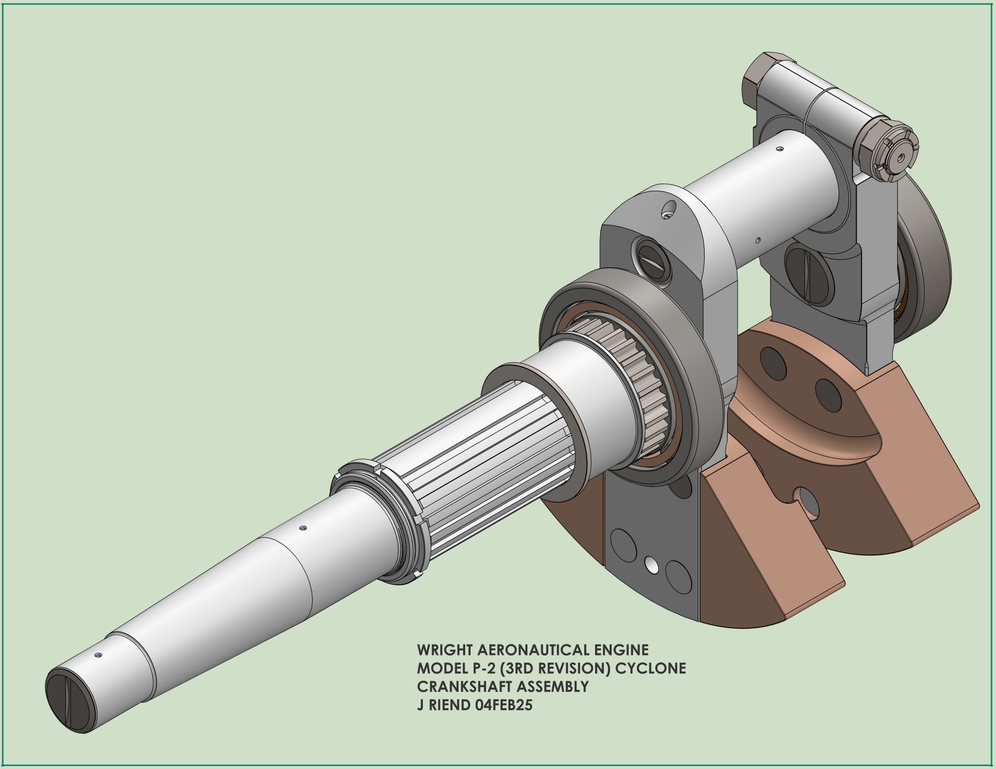
The second revision P-2 (P-2B) had the magnetos and associated drive gears moved aft from mounts on the front crankcase to mounts on the revised main crankcase, a new extended front crankcase which included space in the anticipation of future reduction geartrains. The Intermediate crankcase was redesigned with the intake and exhaust cam drive geartrain mounted below the crankshaft on the rear face of the Intermediate crankcase housing. To accommodate the longer front crankcase the P-2B crankshaft became a longer (still) one-piece crankshaft that utilized the original (and prone to cracks) (6) P-1 master rod. The cylinder heads were fitted with screwed-in fully machined, finned steel cylinder barrels.
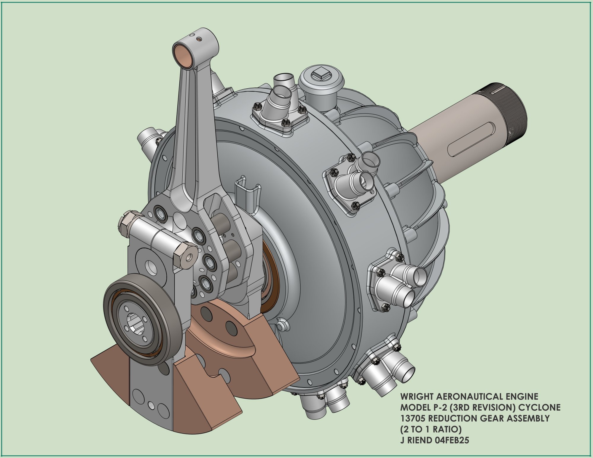
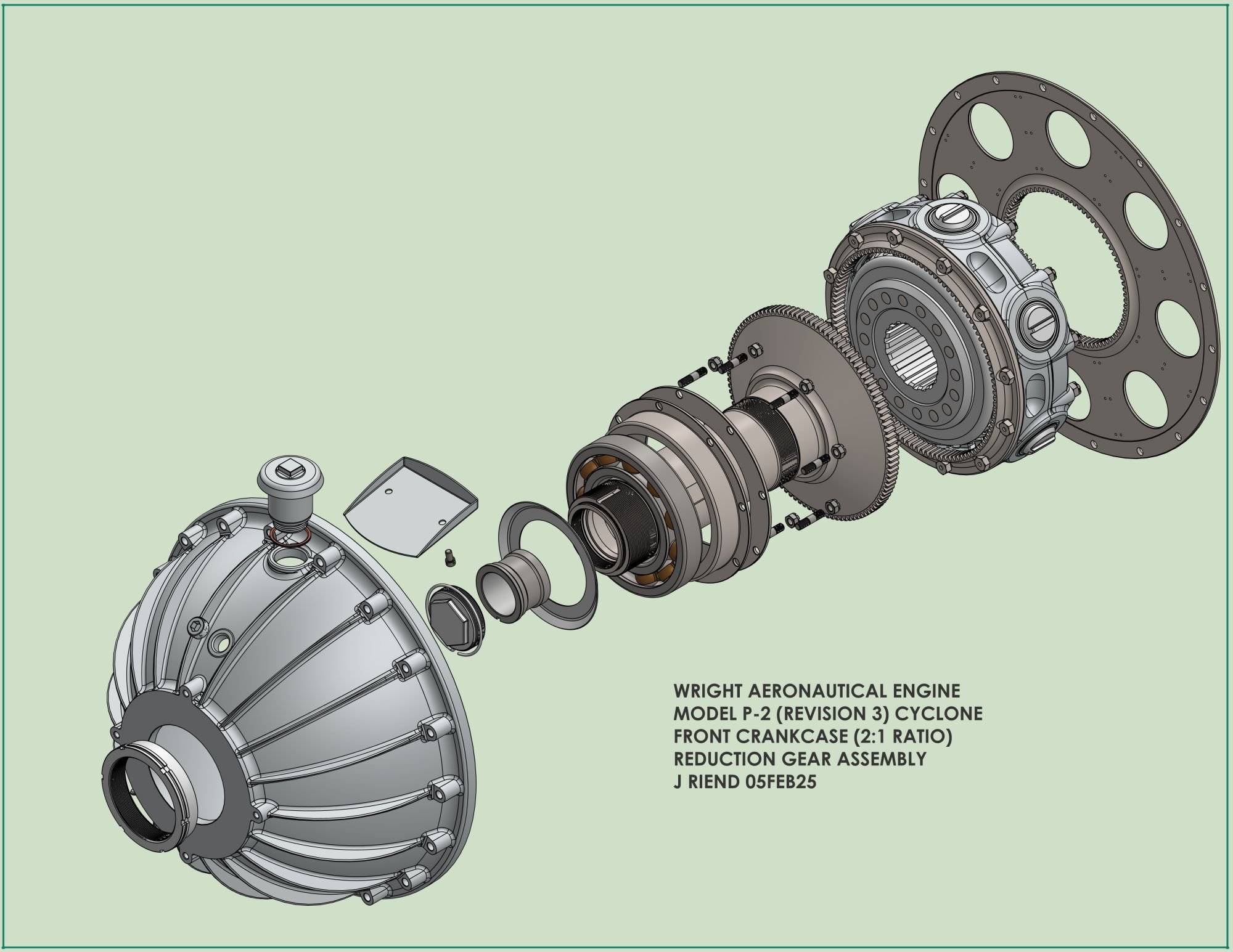
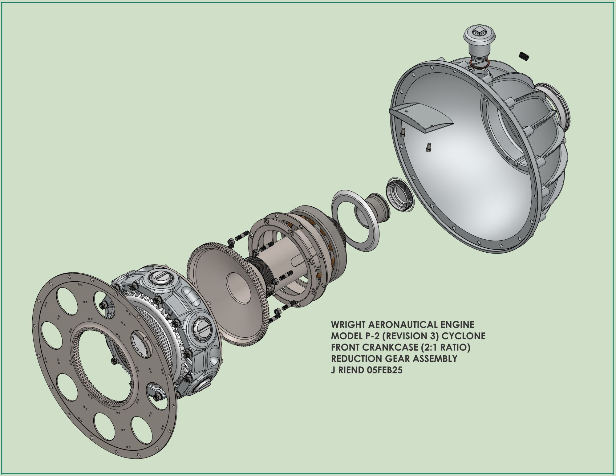
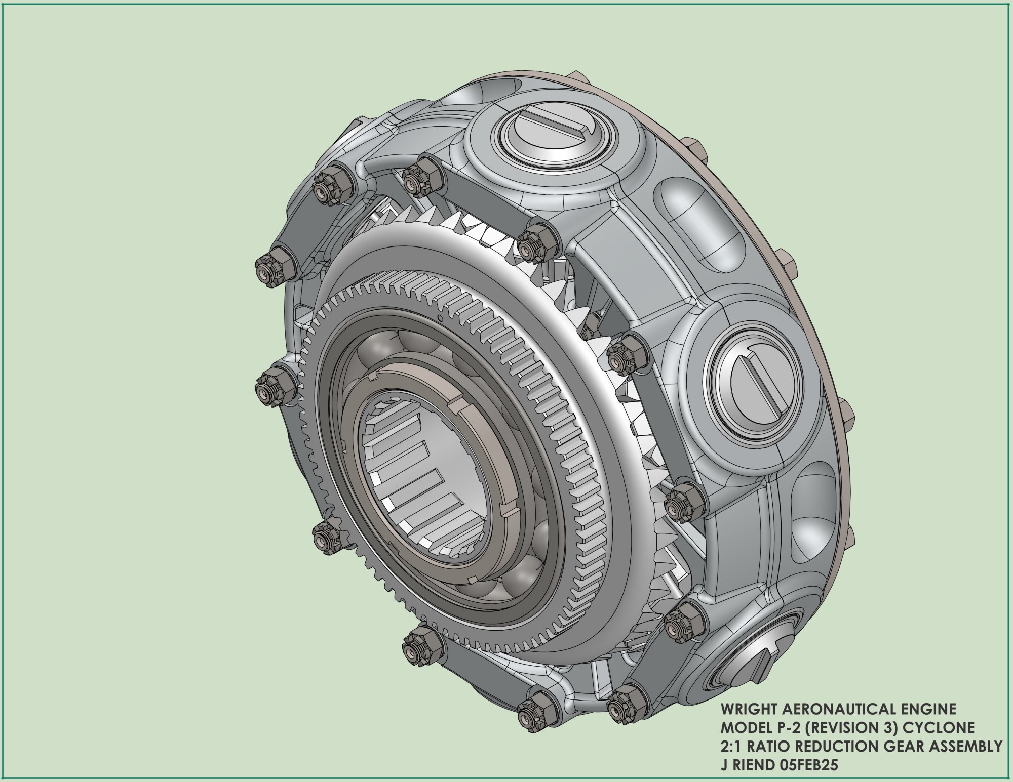
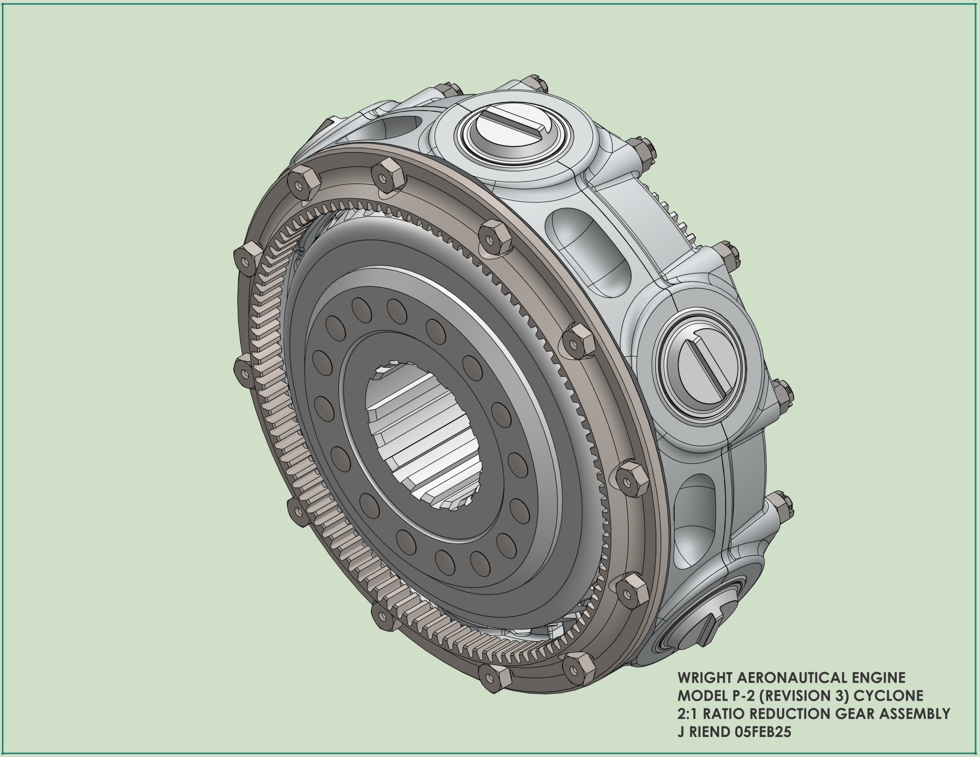
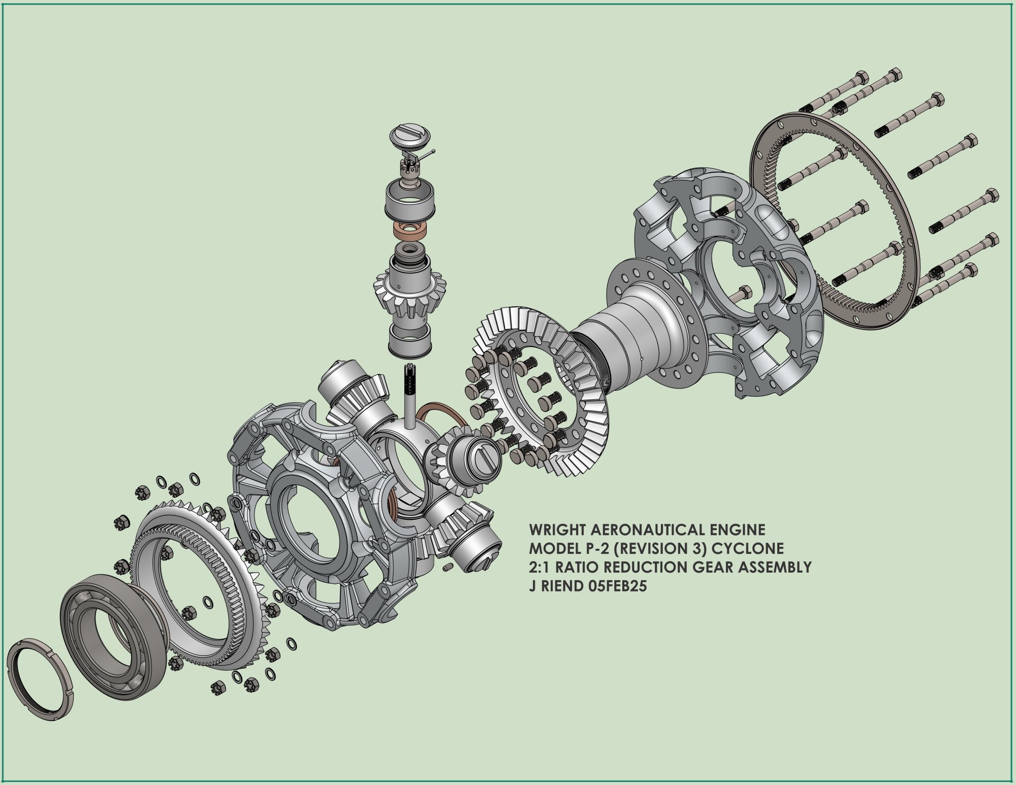
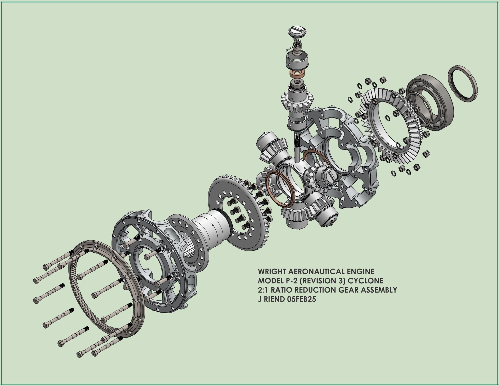
The third P-2 (P-2C) improved on the P-2B with a new two-piece crankshaft and a one-piece master rod along with a 2:1 ratio reduction gearset. It is interesting to note that the P-2C one-piece master rod is a first for a Wright radial engine. Additionally, like the Curtiss R-1454 master rod, the knuckle pin bore locations were adjusted (7) to optimize the piston position during operation.
It turns out that I’m modeling this engine series backwards (it was easier that way). The current batch of P-2C 3D models posted after the supercharger section are those depicted in Drawing No. 13705, Wright Reduction Gear Assembly. In my WAD research last year, I located the P-2B crankcase drawing, so it appears my next project will be to model a complete P-2B engine followed by the complete P-2C and finally the original P-2A engine which utilizes the P-2B crankcase minus the magneto mounting features. Models of the components that are missing drawings will be approximated using the attached associated components and cross sections from the assembly drawing, these include the P-2A main crankcase, P-2B front crankshaft and the P-2B Intermediate crankcase and earlier or later drawings of similar components if available.
13 Oct 2025
Now that the P-2C model is completed, this portion of the WAD engine project is now coming to an end, and it has been an exceptional journey of discovery into the origins of early air-cooled aircraft engines. The evolution of these engines is a testament to ingenuity, experimentation, and the brilliance of pioneering engineering minds, one hundred or so years ago.
The process of collecting and interpreting original engineering drawings—followed by the creation of detailed 3D CAD models—provided invaluable insight into the design principles that shaped early aviation technology. These models represent some of the earliest iterations of high-powered radial engine designs, adding a layer of historical significance to the effort and reinforcing the importance of precision and fidelity throughout the modeling process.
As noted previously, several major component drawings were missing from the archive. To address this, those components were reverse engineered using adjacent parts, assembly cross sections, and by adhering to the tolerances and standards observed across hundreds of WAC drawings.
One pressing question I had going into this project was where the “Cyclone” name came from? The why and when is covered in Cyclone Naming.
Last time (08 Feb 2025), the question was raised as to whether S. D. Heron designed the P-1 and P-2 cylinders. Period literature has largely established that Heron was responsible for designing the heads, cylinders, and valve mechanisms of the Curtiss R-1454 (8), including both the enclosed self-lubricating and non-self-lubricating versions. He is also credited with designing the J, K & M cylinders (9) for the Wright J-5 engine used on Lindbergh’s NYP flight in 1927.
Regarding Heron’s involvement in designing other engines, I have found several references (8, 10) that strongly suggest Heron was also present and actively involved with the team that developed the original Cyclone and Simoon (P-1, P-2, and R-1200) heads and cylinders. All these engines were equipped with his salt- or sodium-cooled exhaust valves. The design similarities to Heron’s work among the listed heads and cylinders are indisputable.
At the end of the Bill of Material for the final P-2C revision, I discovered a list of part numbers for an alternate set of oil pump components. This new oil pump closely resembles the original J-5 design but has been modified to accommodate longer scavenge and pressure gears, while maintaining the original crankcase porting alignments. The gear changes resulted in a theoretical displacement increase of 25% and 37.5% respectively.
Unlike the P-1 and P-2A, the repositioned intake and exhaust cam drive gearing used in the P-2B and P-2C lacks any mechanism for adjusting valve timing.
The P-2B and P-2C impeller maintained the same inlet and outlet dimensions as the P-2A but the vane count went from 15 to 19 and the spring damper coupling in the supercharger drive train was eliminated.
Some additional references (11 – 18) cover much of early air-cooled radial engine history. Most of these accounts were written by or collected from individuals who were directly involved, although some were documented approximately 25 years after the fact, so some dates may not align precisely.
I wish to express my sincere gratitude to Jane Wildermuth, Head Librarian; Toni Vanden Bos, Head of Special Collections and Archives; and their staff at Wright State University Libraries for their generous support and assistance in fulfilling my numerous scan requests. Their expertise and responsiveness have been instrumental to the success of my research.
Special Thanks to Kimble McCutcheon for his time, hard work and expertise arranging, laying out and posting my drawings and renders as well as maintaining the AEHS website.
The End
Rererences:
1. National Air and Space Museum Technical Reference Files: Propulsion | Collection: NASM.XXXX.1183.B
2. Rolls-Royce Heritage Trust – Allison Branch Annex, 1911 Executive Drive Suite A, Indianapolis, IN 46241. Email: HeritageIndy@RRHTAB.org
3. Allison Engineering Co. Gilman Spring Coupling U.S. Patent 1,581,084.
4. C-W Shipments, 1920-1964 AEHS p. 18
5. Senate Hearings S Res 206 George J Mead 1934, p. 136
5a. NACA 11th Annual Report 1925, p. 81
6. 50 Hour Endurance Test and Sea Level Performance Characteristics of the Wright Model P-1 Engine #10062 Mfg. # 6477, WAC-15. Wright Aeronautical Corporation, Paterson, New Jersey (1 Apr 1925), NASM Propulsion Tech Files, BW-719000-01.
7. Angle, Glenn D. "Positioning of Link Rod Wrist Pins in Articulated Connecting Rods" (New York: Aviation Engineering, Jan. 1932, v. 6, no. 1) 11-14 diagrams.
8. Development of Aircraft Engines, Robert Schlaifer, 1950, p. 177 - 192.
9. Air Service Information Circular, Vol. V, No. 425, Technical Bulletin No. 32, p. 16 (K-head)
10. The Curtiss D-12 Aero Engine, Hugo Byttebier, p. 69, 81.
11. Air-Cooled Engines in Naval Aircraft, by E. E. Wilson, SAE Transactions, Vol. 21, PART II (1926), pp. 812-846
12. Smithsonian Annals of Flight, V 1, N4, A Review of the Evolution 0£ Aircraft Piston Engines, C. F. Taylor, p. 46
13. Aero Propulsion and Power Directorate, The McCook Field Years 1917-1927, Misenko 1995, p. 105
14. The Wright Cyclone Aviation Engine, Aviation Week & Aeronautical Engineering 1925-02-16 Vol 18 N 7, p. 185.
15. Janes All the Worlds’ Aircraft 16th 1926, p. 55c
16. Air-Cooled Engines for Aircraft, R. Insley, Scientific American, August 1927, pp. 148-151, 181-182.
17. The autobiography of an aircraftsman, Slipstream, E. E. Wilson, 1950.
18. The New Wright “Cyclone”, Aviation V18 N21 25 May 1926, p. 567.
Wright Aviation Engine, Model P-2B
 |
| Large Image in Members' Section |
 |
 |
 |
 |
| Front | Left | Aft | Right |
 |
 |
 |
 |
| Top Left Front | Top Right Aft | Longitudinal Cross Section | Drawings (Members' Section) |
Wright Aviation Engine, Model P-2C
 |
 |
 |
 |
 |
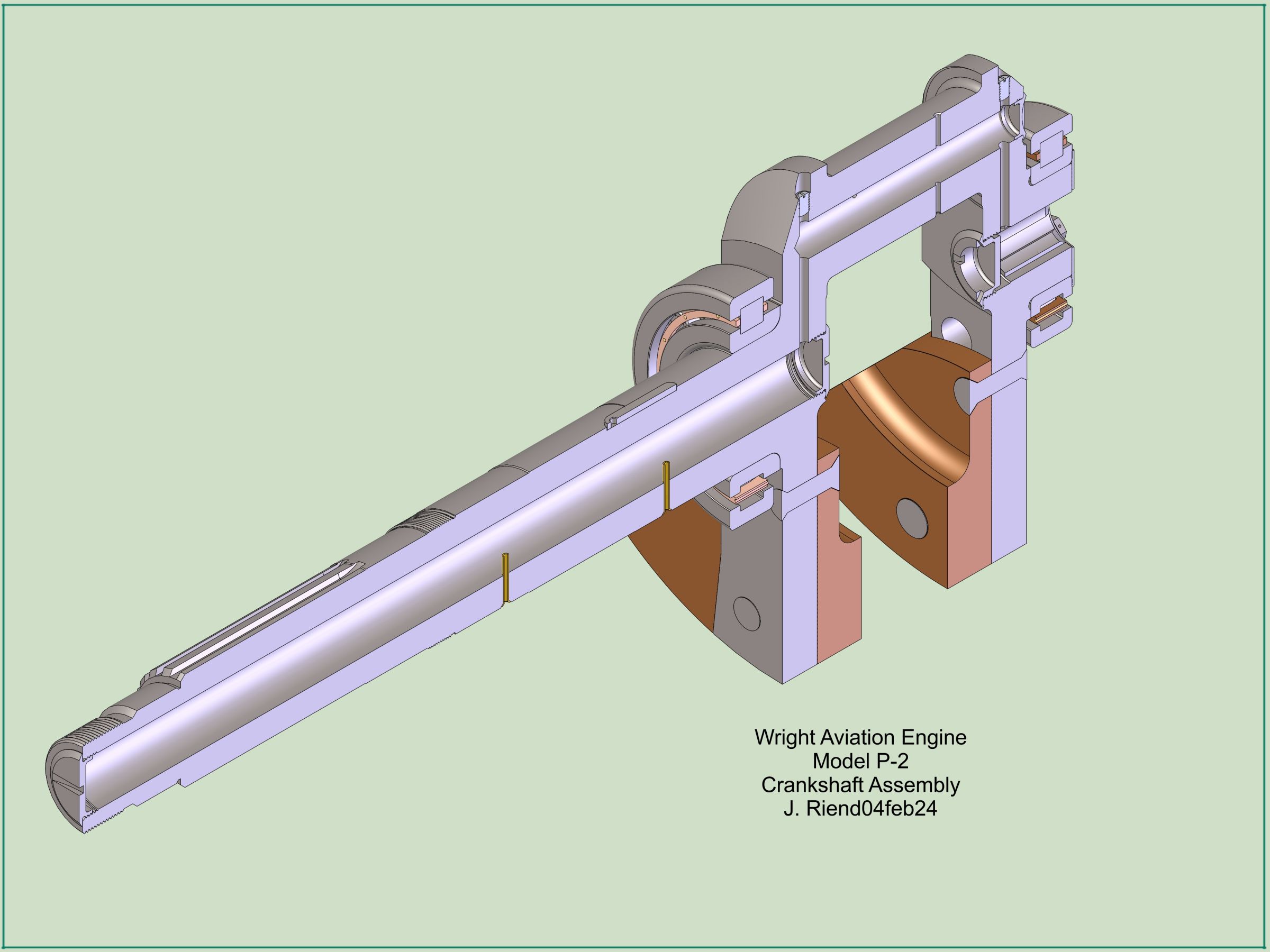
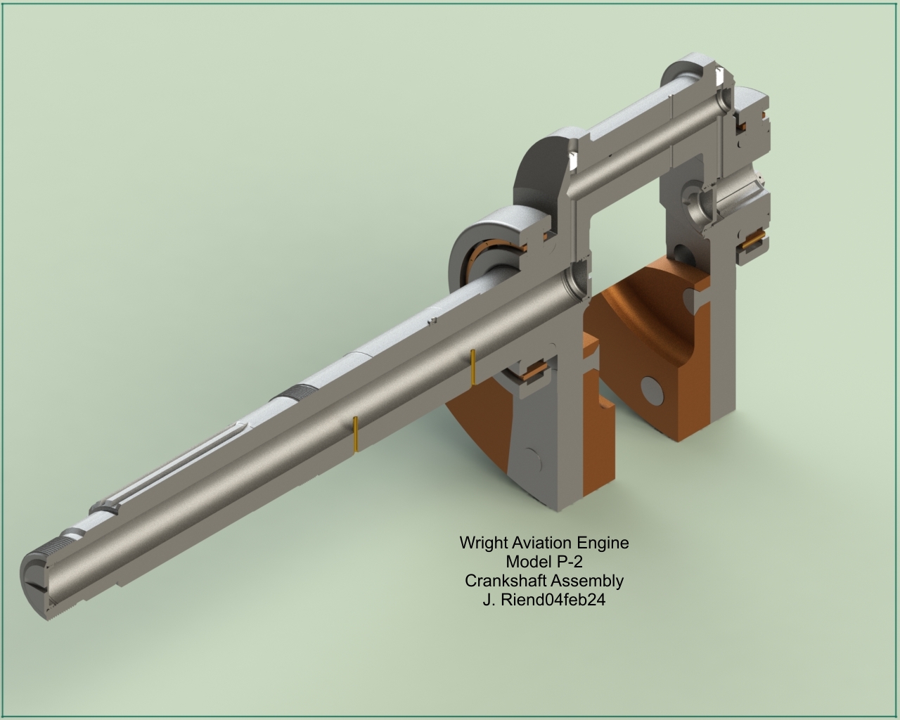
| Front | Left | Aft | Right | Longitudinal Cross Section |
 |
 |
 |
 |
 |
| Top Left Front | Top Right Aft | Exploded View | Drawings (Members' Section) | Oil Pump (Members' Section) |
 |
 |
 |
 |
 |
 |
 |
 |
 |
 |
 |
 |
| Large Image in Members' Section |
 |
 |
 |
 |
Send mail to
![]() with questions or comments about this web site.
with questions or comments about this web site.
![]()