 |
enginehistory.org
Aircraft Engine Historical Society Members' Bulletin Board
|
| View previous topic :: View next topic |
| Author |
Message |
hkewenter
Joined: 13 Jul 2003
Posts: 2
|
 Posted: Mon Sep 18, 2006 08:56 Post subject: Rocker arm contact surface Posted: Mon Sep 18, 2006 08:56 Post subject: Rocker arm contact surface |
 |
|
Hello,
I have a question regarding rocker arms, or actually the surface contacting the valve stem tip.
As far as I can see, the ideal surface should be one which “rolls” of the valve stem during the valve travel motion and thus the evolute comes to mind.
I have tried to find out where the generating circle should be centered for a evolute-generated surface of this kind but I don’t seem to get it right. After Mr Miller’s article about R-R PRSU gears in latest TM I got fuel for thoughts but to no avail, so can anyone (mr Miller?) explain the mathematically correct surface and how it is generated for the rocker arm contact surface?
I have never found any litterature on this matter either so any references would be most appreciated as well!
Thanks in advance,
Hans |
|
| Back to top |
|
 |
kmccutcheon

Joined: 13 Jul 2003
Posts: 299
Location: Huntsville, Alabama USA
|
 Posted: Wed Sep 20, 2006 04:55 Post subject: Posted: Wed Sep 20, 2006 04:55 Post subject: |
 |
|
Dear Hans,
Mr. Miller sends the following reply:
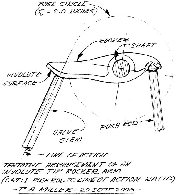
| Quote: | Smeared pencil lead all over a big white Torque Meter envelope which I've found is excellent scratch paper. It worked again! The base circle is centered on the rocker arm shaft centerline and you swing an involute out a bit from the base circle as though you were going to draw half of an involute gear tooth. The valve stem and the line of action of the valve's opening and closing are aligned and centered over a tangent to the base circle just as the similar contact line serves mating involute gear teeth. The involute curve surface of the rocker extends a out from the base circle far enough to keep the tangent line of action and the valve stem from getting too near the tight radius portion of the involute curve.
The rough sketch is not to an exact scale and not full size but is pretty well in proportion to support a rudimentary schematic look via analytic geometry.
For the analytics I chose a 2.0" r_b (base circle radius) and figured that a conventional rocker arm equivalent to the involute ended version would have about 2.25" radius from rocker CL to the valve stem CL. Not knowing what size engine was being considered I chose a "big enough" chordal " lift" of 0.75" on the base circle and up to 0.844 out on the conventional rocker arm (dependant on the tip radius configuration). The "rise" of a uniform lift involute cam for the same angular rocker arm rotation (21.614 degrees) was figured from Buckingham ar 0.7545". The 0.844" travel may well be a bit optimistic while the 0.7545" involute curve rocker end travel figure seems solid and certain.
BUT it does appear as though a small percentage of lift will be lost in adopting an involute curve to a valve opening rocker arm. This can be made up in rocker arm length ratios or cam lift changes early in the design process but could be a bit inconvenient for retrofit.
The involute version will, however, load the valve stem continuously at the CL parallel to the rocker shaft if it is initially so aligned. The rubbing velocity of the involute will serve a typical stem end valve rotating scheme or operate, likely without complaint, with a free rotating stem end cap if desired. |

_________________
Kimble D. McCutcheon
Last edited by kmccutcheon on Mon Sep 25, 2006 20:28; edited 2 times in total |
|
| Back to top |
|
 |
hkewenter
Joined: 13 Jul 2003
Posts: 2
|
 Posted: Wed Sep 20, 2006 09:53 Post subject: Posted: Wed Sep 20, 2006 09:53 Post subject: |
 |
|
Thanks for the fast reply and the most impressive explanation!
I have discussed this with several of the best engineers I know but no-one has managed (or cared) to explain it fully.
Looking forward to see a drawing and further info!
Please thank Mr Miller if he doesn't read this.
Hans |
|
| Back to top |
|
 |
|
|
You cannot post new topics in this forum
You cannot reply to topics in this forum
You cannot edit your posts in this forum
You cannot delete your posts in this forum
You cannot vote in polls in this forum
|
Powered by phpBB © 2001, 2005 phpBB Group
|


