 |
enginehistory.org
Aircraft Engine Historical Society Members' Bulletin Board
|
| View previous topic :: View next topic |
| Author |
Message |
gryan
Guest
|
 Posted: Wed Sep 01, 2004 15:00 Post subject: Connecting rods for V-engines Posted: Wed Sep 01, 2004 15:00 Post subject: Connecting rods for V-engines |
 |
|
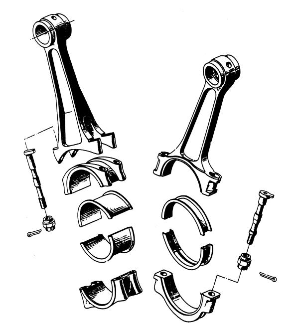
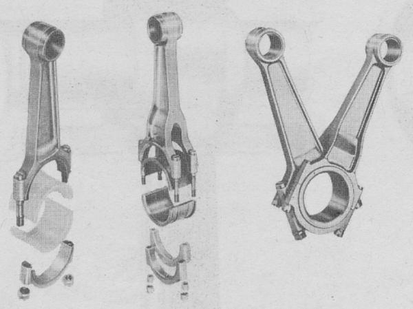
I was looking at drawings of connecting rods (of the fork and blade type) from the Rolls Royce Merlin and the Allison. I have two questions.
1/. Why did the aviation engine manufacturers go to all the elaboration of the fork and blade arrangement instead of the far simpler arrangement of placing the rods side by side on the journal (as is done in automotive vee engines)? The side by side arrangement would result in reduced parts count and easier manufatcuring. It was well known at the time so there must have been some other reason behind the decision not to employ it.
2/. The RR Merlin forked-rod assy is is three piece design (excluding fasteners). It is clear how machining the outer diameter, for the blade rod bearing to run on, would have been accomplished. On the other hand the Allison fork rod design appears to be a two piece design. Given the presence of the rod shank, how was this connecting rod machined so the blade rod could be supported on its outer diameter? It would need to be machined (turned?) concentric with its inner diameter but this would be difficult to accomplish with the shank of the rod in the way. How was it achieved?
Regards
Gerald Ryan |
|
| Back to top |
|
 |
kmccutcheon

Joined: 13 Jul 2003
Posts: 299
Location: Huntsville, Alabama USA
|
 Posted: Sun Sep 05, 2004 04:45 Post subject: Posted: Sun Sep 05, 2004 04:45 Post subject: |
 |
|
I was hoping someone else would take a stab at this, but since no one has, I shall give it a try.
| Quote: | | Why did the aviation engine manufacturers go to all the elaboration of the fork and blade arrangement instead of the far simpler arrangement of placing the rods side by side on the journal (as is done in automotive vee engines)? The side by side arrangement would result in reduced parts count and easier manufatcuring. It was well known at the time so there must have been some other reason behind the decision not to employ it. |
I can offer several observations that may have led designers to choose fork and blade connecting rods:
1. The engine would have been shorter (in a V-12, by at least six times the width of the connecting big end).
2. The shorter engine would have been lighter in weight.
3. The shorter, and hence stiffer, crankshaft would have been less prone to troublesome bending and torsional misbehaviors.
4. Side-by-side rods introduce a rocking couple that can have unpredictable vibration effects. In very large engines, even a small percentage of power manifested as vibration can have disastrous consequences if some engine part is sympathetically excited.
In the USA during World War II, three large automobile companies (Chrysler, Ford and Studebaker) tried to design large liquid-cooled aircraft engines. The Ford engine used side-by-side connecting rods, but was abandoned for a number of reasons. The other two used fork and blade rods. Only the Chrysler ever flew.
| Quote: | | The RR Merlin forked-rod assy is is three piece design (excluding fasteners). It is clear how machining the outer diameter, for the blade rod bearing to run on, would have been accomplished. On the other hand the Allison fork rod design appears to be a two piece design. Given the presence of the rod shank, how was this connecting rod machined so the blade rod could be supported on its outer diameter? It would need to be machined (turned?) concentric with its inner diameter but this would be difficult to accomplish with the shank of the rod in the way. How was it achieved? |
As you have observed, the Merlin three-piece fork connecting rod design was a way to provide a bearing journal for the blade rod.

The Allison Company was an innovator in the design and production of steel backed bearing shells. Allison used an “inside-out” bearing design for the blade rod. The bearing shells had bearing alloy on the inside diameter shells, as was usual practice. In addition, the outside diameter also had a central band of bearing alloy that interfaced with the inside diameter of the blade rod. This meant that the Allison rod big ends could be produced with simple boring and honing operations.

Hope this helps.
_________________
Kimble D. McCutcheon |
|
| Back to top |
|
 |
mgruver
Joined: 10 Sep 2004
Posts: 1
|
 Posted: Sun Sep 19, 2004 22:05 Post subject: Posted: Sun Sep 19, 2004 22:05 Post subject: |
 |
|
| Hi, I am a new member and a young guy, so I dont know much. I do know a little about Automotive engines though. Anyway, I have been wondering, how does the blade rod bearing recieve oil? And why did they have to build a journal for hte blade rod into the fork rod? I mean, couldn't they have let the fork rod bearing ride on the journal in between the blade rod; it would seem less complicated to do so, but I must be missing some design consideration... same with Allison; they have a simpler setup but still it would seem simpler to me to have one bearing on inside the blade rod and two in the fork rod, all riding on the journal.... Hope to get another enlightning response such as the ones above. |
|
| Back to top |
|
 |
kmccutcheon

Joined: 13 Jul 2003
Posts: 299
Location: Huntsville, Alabama USA
|
 Posted: Mon Sep 20, 2004 05:09 Post subject: Posted: Mon Sep 20, 2004 05:09 Post subject: |
 |
|
| Quote: | | I have been wondering, how does the blade rod bearing recieve oil? |
I am currently traveling and don't have access to my library, but I believe the blade bearing receives oil via a drilling that connects the interior of the fork bearing to the the (exterior) blade bearing. I shall verify this upon my return home and post a retraction if it is untrue.
| Quote: | | And why did they have to build a journal for hte blade rod into the fork rod? I mean, couldn't they have let the fork rod bearing ride on the journal in between the blade rod; it would seem less complicated to do so, but I must be missing some design consideration... same with Allison; they have a simpler setup but still it would seem simpler to me to have one bearing on inside the blade rod and two in the fork rod, all riding on the journal. |
If the fork rod were journaled directly on the crankpin, it would have to have a larger bearing area to deal with rotating considerations. As it is, the fork-and-blade design allows both connecting rods to "double up" on a single bearing with an area that is large enough to handle the forces resulting from the combination, but still smaller than the total area that would be required if each rod were journaled directly on the crankpin. Since the fork rod rocks back and forth on its bearing, it needs less area than if it were a full rotating bearing. To my way of thinking, this situation is analogous to the relative sizes of the master rod bearing and knuckle pin bearings of a typical radial engine connecting rod system - the master rod bearing is huge, but the knuckle pin bearings are much smaller by comparison.
_________________
Kimble D. McCutcheon |
|
| Back to top |
|
 |
szielinski

Joined: 13 Jul 2003
Posts: 94
Location: Canberra, Australia
|
 Posted: Wed Sep 22, 2004 23:31 Post subject: Posted: Wed Sep 22, 2004 23:31 Post subject: |
 |
|
| Doubling up on the bearing shells also gives two oil films. |
|
| Back to top |
|
 |
|
|
You cannot post new topics in this forum
You cannot reply to topics in this forum
You cannot edit your posts in this forum
You cannot delete your posts in this forum
You cannot vote in polls in this forum
|
Powered by phpBB © 2001, 2005 phpBB Group
|


