
The de Havilland Ghost 48
Part 1: Engine Components
| Thanks to Bruce Vander Mark for for scanning and making this material available from his collection. |
 |
 |
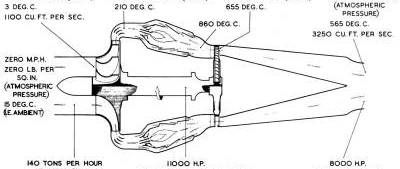
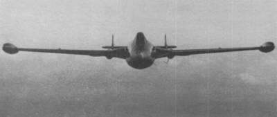
| Fig. 1. Gas flow, or working cycle diagram | Fig. 3. Air-intakes in the leading edges of the Venom wings |
 |
 |
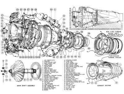
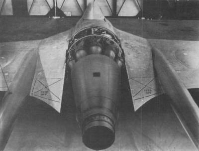
| Fig. 2. Exploded view of Ghost 48 Mk. 1 | Fig. 4. Ghost in Venom fighter showing exhaust nozzle |
The remainder of this page is available only to AEHS Members. Please Login.