
Regenerative Dynamometers
A Means of Utilizing Power Developed on Aircraft Engine Test Beds: Heenan and Froude Development
| This article first appeared in the Volume 5, Number 61 (November, 1943) issue of Aircraft Production magazine, and is presented here through the kind permission of Flight International. Thanks also to Bruce Vander Mark for furnishing volumes of Aircraft Production for scanning. |
 |
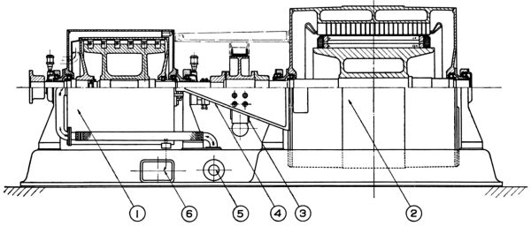
| Diagrammatic layout of Heenan AC Regenerative Dynamometer. Key: (1) dynamatic coupling brake. (2) alternator. (3) friction brake. (4) torque yoke. (5) water inlet. (6) water outlet. |
An announcement in the last issue related to Heenan and Froude's regenerative dynamometer for aircraft engine test beds. This development is indeed interesting at this particular period of short fuel supplies and also in view of the advocacy by Aircraft Production some 18 months ago of means of utilizing in other parts of the factory the power developed by aircraft engines under test.
Of the AC regenerative type, the dynamometer consists in essentials of a constant-speed alternator coupled to the engine by an eddy-current magnetic coupling, slip being automatically controlled by electronic means. At low speed, the alternator rotor is held stationary by a friction brake, the coupling in these conditions working at 100% slip and thus absorbing the full power output of the engine.
Heenan and Froude hold the license of the Dynamatic Corporation of Kenosha, Wisconsin, and have perfected a regenerative dynamometer, similar in broad principle to the test beds in use at Buick Motors aircraft engine division, but modified as necessary to suit British requirements.
Powered by phpBB © 2001, 2005 phpBB Group |