
The Cheetah X
Part 2: Machining the Cylinder Unit, Induction Casing Rear Cover and the Crankcase; Assembly and Testing
By J. A. Oates, M.Inst.Met., A.M.I.E.I.
|
Concluding the manufacture of major components for the well-known Cheetah X engine at one of the Armstrong-Siddeley factories, we describe in this issue the more interesting operations connected with machining the cylinder unit, induction casing rear cover and the crankcase. This article first appeared in the Volume 5, Number 59 (September, 1943) issue of Aircraft Production magazine, and is presented here through the kind permission of Flight International. Thanks also to Bruce Vander Mark for furnishing volumes of Aircraft Production for scanning. |
The cylinder assembly comprises a steel barrel screwed and shrunk into an aluminium alloy head, the two components being further secured by a drilled locking ring that acts as a fin. On the barrel there are 14 fins approximately one inch deep and spaced 0.255" apart; they are machined from solid metal, and have their sides tapered to an included angle of 40°.
The cylinders are secured in the crankcase by steel adaptors threaded internally to correspond with the thread on the cylinder barrel; they are fitted into the crankcase cylinder sockets and prevented from turning by a locking peg and circlip. The cylinder is locked by two beveled sides of the cylinder barrel locking ring; one bears against the crankcase socket and the other against the lip on the cylinder barrel. The bore is 5.25 ±0.0005" diameter and the length is 9.425".
Cylinder head cooling is achieved with deep, close-pitch fins cast integral with the head. Screwed and shrunk in the head are two valve seats and also sparking plug adaptors, the latter being further secured by dowel pins. Fitted to each cylinder are two valves, the exhaust valve being sodium cooled and provided with a 91° seating; both valves are operated by push-rods and rockers, and are each fitted with two springs.
 |
 |
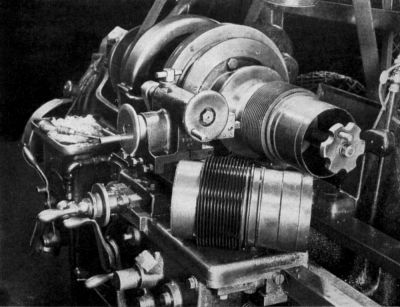
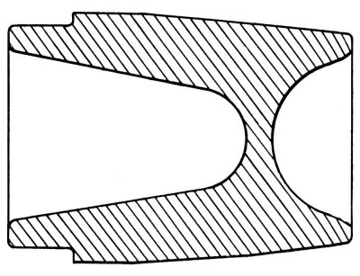
| Fig. 32. A lathe specially adapted for removing the half thread at each end of the screwed portion. | Fig. 33. A cross section of the cylinder barrel forging prior to machining. |
The remainder of this article is available only to AEHS Members. Please Login.