Torque Meter
Fall 2008 Issue
 |
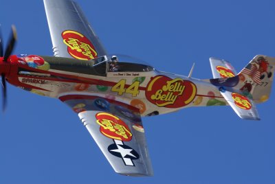 |
Reno 2008: The World’s Fastest Motorsport at its Best The Reno National Championship Air Races of 2008 must go into the history books as one of the best in the event’s 45 years. Not only was the weather perfect, but so was the flying and competition. With five days of competition by six classes of aircraft, along with one of the best competitions for restored historic aircraft, (Rolls-Royce Heritage Trophy), world class aerobatic displays by all sizes and types of aircraft from the Pitts Special to the USAF F-22 Viper, and the USAF Thunderbirds, there is something for every ardent airplane nut, enthusiast, and fan. This year the excitement was enhanced by having two very competitive Merlin-powered airplanes. The record setting Dago Red was back in the fray after sitting out for a year, along with a rebuilt race Merlin in Strega. September Fury had a newly built R-3350-93 replacing the one broken last year, and a considerably reworked Rare Bear was lurking in its lair looking like it was ready to pounce. Where last year the round engines ran the Merlins to the ground, it looked like this year things just might be different! |
 |
Report from the 5th Annual AEHS Convention |
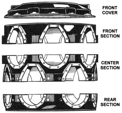 |
Bristol Hercules Components The crankcase comprises four light-alloy forgings, machined on most surfaces, and bolted together to form a single unit. These parts are the front cover, front section, center section, and rear section. The front and center sections each house seven sleeve-crank ball bearings, and all three sections carry a main roller bearing for the crankshaft. In addition, the front section also carries seven sets of gears, a total of 21. Around the unit are 14 faces for attachment of the cylinder. The front and the rear sections are machined with seven sides, and the center has two sets of seven sides. For lightness, the case is recessed or pocketed, leaving the cylinder faces in relief. The various sections enter the shop as stampings, from which a considerable amount of material is removed during machining. |
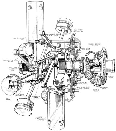 |
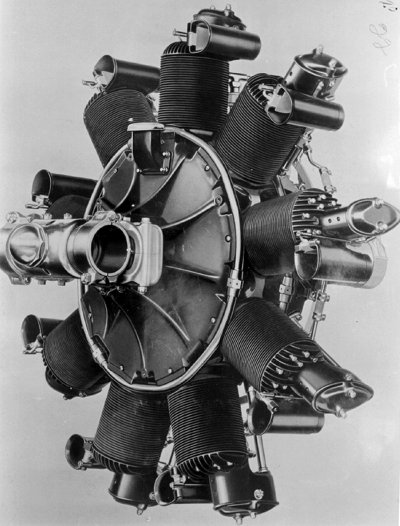
The Bristol Hercules, Part 3: The Gear Department, Engine Assembly and Testing, Heat-Treatment and Process Sections, Laboratories and Standards Room This article first appeared in the Volume 4, Number 42 (April, 1942) issue of Aircraft Production magazine, and is presented here through the kind permission of Flight International. This concluding installment describing the manufacture of the Hercules engine at one of the Shadow Factories mainly concerns final assembly and testing, and also describes some of the process departments and laboratories. It is natural that a very close check is kept on everything concerned with both the engine and the equipment used for its production. The quality of raw materials, bearing metals, coolants, oils, carburising compounds and gauges, to mention but a few items, are all controlled from the laboratories. There are a considerable number of gears in the Hercules engine, and these are made in a separate department fitted with practically every type of modern gear-generating plant and testing apparatus. A Hey tooth-edge radiusing machine is designed specially for removing the sharp edges by milling a small radius of 2-4 mm on both ends of the tooth profile. The machine is fully automatic after loading, and has a special patented profile device to reproduce the exact contour of the tooth during the rounding operation, so as to obtain an equal chamfer or radius along the whole profile of the tooth, including both the top of the tooth and the root, as well as the sides. A very small diameter cutter, running in high-precision Timken bearings at approximately 8,000 rpm is used. |
 |
Packard as an Aero Engine Builder Earlier articles of this series, "Packard as an Aero Engine Builder 1919 - 1923" and "Spark Ignition Engines: 1923-1939" appeared in Vol. 1 No. 4 (Winter, 2002) and Vol. 7, No. 3 (Summer, 2008) of Torque Meter. These articles are excerpted from Master Motor Builders, by Robert J. Neal. The Diesel engine principal, of course, had its roots in Germany. It seems logical that its earliest development for use in airplanes might also have initiated there — and so it was, by Dr. Hugo Junkers. His first aircraft Diesel design was the MO-3 of 1913. It was followed by the 1914 MO-8 and the 1916 FO-2. These were large engines by aircraft standards, the FO-2 being rated at 500 hp. All of these engines were experimental and none ever flew an airplane. WWI halted German progress and it was not until 1926 that the 830 hp FO-3 was exhibited at the International Exhibition in Berlin. It was the exhibition of this engine in 1926 that seemed to initiate active interest in Europe and the United States in aircraft Diesel development. Packard’s first serious interest in the development of Diesel engines seems to have come after studying U.S. patent 1,628,657 dated May 17, 1927, and issued to Hermann I. A. Dorner of Hanover, Germany. This patent covered the design of a solid-type fuel injection system for Diesel engines. Capt. Woolson, Packard’s chief aeronautical engineer, tested both an air-cooled single-cylinder 7 hp and a four-cylinder 30 hp water-cooled Diesel engine built by Dorner. Both proved to be efficient and durable and favorably impressed Woolson. |
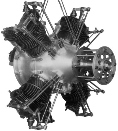 |
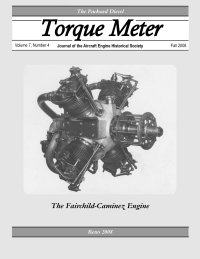
The Fairchild-Caminez Engine In 1923, while in the employ of the U.S. Army at McCook Field, Ohio, Mr. Wilbur Caminez became curious about the possibility of replacing the traditional crank and connecting rod method of converting linear motion to rotary motion. He suggested the use of a double-lobed cam on the driveshaft, the cam being directly driven by pistons with large roller bearings in their base, the bearings being kept in constant contact with the cam with paired link rods connecting the adjacent pistons in a rhombic parallelogram. The design produced a driveshaft (camshaft from hereon) running at half normal crankshaft speed, with every cylinder completing a power stroke on every revolution of the camshaft. If the power translation process proved both mechanically sound and the engine capable of being integrated into the light planes of the period, the approach would offer significant advantages within its power range. The advantages included fewer parts, a superior power to weight ratio and higher propeller efficiency due to lower propeller speeds. An engine producing up to 135 hp with a weight of only 340 lbs would offer the industry an ideal replacement for the many OX-5 engined aircraft in use or on the drawing boards. The design offered many apparent improvements in lower operating costs and increased payload over the OX-5 and a significant market appeared in the offing. This engine was initially known as the Caminez Engine or Radial Cam Engine during its genesis at McCook Field and then as the Fairchild-Caminez Engine after Fairchild purchased the rights and hired Mr. Caminez to direct engine development. |
