Torque Meter
Summer 2008 Issue
 |
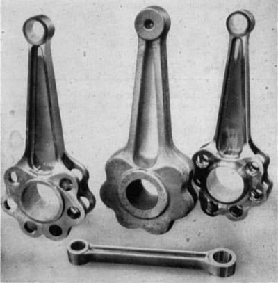 |
The Bristol Hercules, Part 2: Production of the Master Connecting Rod, This article first appeared in the Volume 4, Number 41 (March, 1942) issue of Aircraft Production magazine, and is presented here through the kind permission of Flight International. In this second installment describing the manufacture of 14-cylinder Hercules double-row sleeve-valve engines, we continue with the description of machining operations on several of the more important components. The division of the production schedule for the master connecting rod into approximately 110 simple operations, capable of being performed in most cases by female or semi-skilled labour, is particularly noteworthy. The wider adoption of this policy has been repeatedly urged for the past two years by leading production engineers, and the Hercules provides a striking example of the success of the scheme. |
 |
The Great Funk "E" Crankshaft Mystery The Funk inversion of the Ford "B" engine was thoroughly thought out and had a reputation for admirable specific fuel and oil consumption. The Funk "E" featured a very sturdy 9.5-inch long prop shaft literally grafted rigidly and permanently to the former rear main end of the forged steel "C" crank (pressed, doweled, bolted, likely machined in situ and not to be removed). A cast aluminum nose case was doweled and bolted to the block. It supported a large rolling-element bearing on the crank extension approximately two inches beyond the crank’s former flywheel end. The bearing took both radial and thrust loads. Two Funk Aircraft Co. Funk "E" Service Bulletins, numbers 12 and 16 of 4 June 1940 and 3 October 1940 warned of cracks in the filet area of the crankpin toward the crank centerline and adjacent to the propeller end main (the former automotive rear main). The "E" engine was left with a requirement of rod cap removal and visual crankpin inspection every 50 hours plus a teardown and crank Magnaflux inspection every 100 hours. I was puzzled. A production forged crankshaft that in my reckless youth I could not break no matter WHAT I did to abuse it and it is ready to give up after 50 hours of 63 hp at 2,125 rpm? Now that’s a mystery! |
|
Aero Engine Drawing |
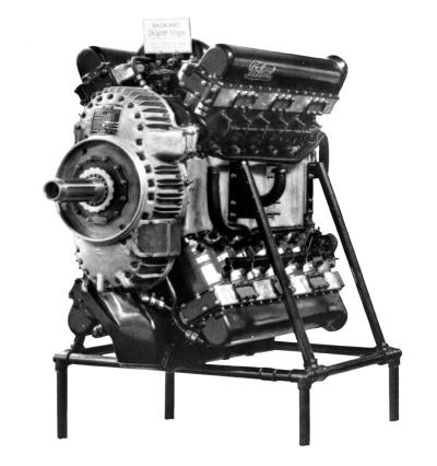 |
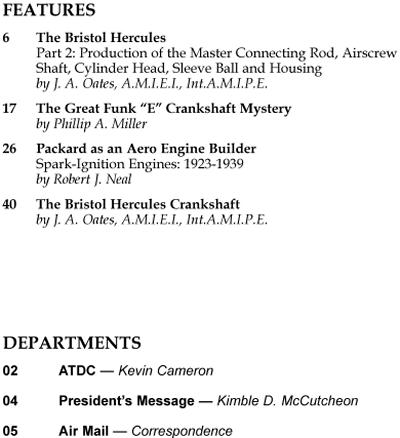
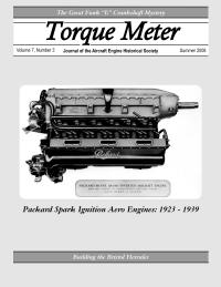
Packard as an Aero Engine Builder The initial article of this series, "Packard as an Aero Engine Builder 1919 - 1923", appeared in Vol. 1 No. 4 (Winter, 2002) of Torque Meter, and features the history of earlier Packard aero engines. Like the earlier one, this article is excerpted from Master Motor Builders, by Robert J. Neal. By late 1922 Packard was ready to take another engineering step in the development of their aero engines. They were looking for a reduction in weight, more power and more reliability. As in the past, they went to the Army and Navy for development contracts, as the great majority of their aero engines to this time had been built for the services. |
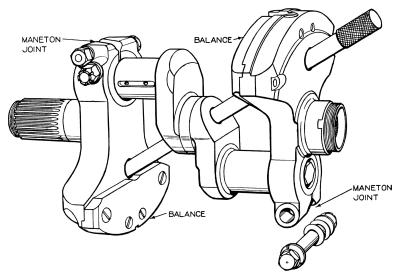 |
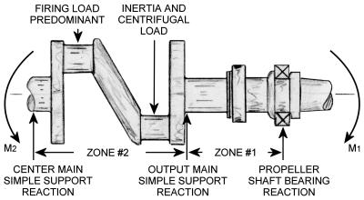
The Bristol Hercules Crankshaft This article is excerpted from one that appeared in the Volume 6, Number 64 (February, 1944) issue of Aircraft Production magazine, and is presented here through the kind permission of Flight International. In addition to the influence of design, the success of the engine is due largely to the high standards of accuracy and surface finish maintained during manufacture of the various components, and a good example of this is provided by the skill and care exhibited during the manufacture of the crankshaft. The design of this important component follows accepted radial engine practice and consists of a built-up three-piece unit which allows the use of solid master connecting rods. From the production viewpoint this would appear to have advantages also, as jig and fixture design is simplified, smaller machine tools may be used for many operations, and several operators may work simultaneously on the same crankshaft. |
