Torque Meter
Winter 2007 Issue
 |
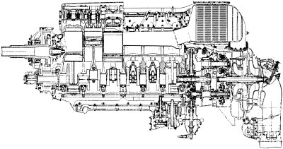 |
Early Intercooled Merlins In the aero-engine literature, accounts and accolades abound of, and for, the 60-series Rolls-Royce Merlin engine with its prominent box-shaped intercooler radiator sitting atop the two-stage, two-speed supercharger The use of an intercooler on the 60-series Merlins was the first instance of such a component being incorporated on a production engine from R-R but prior to this, a lot of thought and quite a bit of practical work had been applied to the subject using engines with single-stage superchargers. |
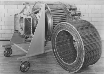 |
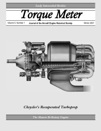
Chrysler's 1,000 HP Recuperated Turboprop When World War II ended the automobile manufacturers in Detroit were already making plans to convert their factories back to civilian production. Like the other auto companies Chrysler Corporation had made major contributions to the war effort but was anxious to return to its primary business of building automobiles. At Chrysler’s corporate headquarters, the Research Department was wrapping up work on a major wartime development program, the 2,500 hp XI-2220 inverted V-16 aircraft engine. Anticipating the switch to gas turbine powerplants for future aircraft designs, Chrysler had begun preliminary studies for a company-funded gas turbine engine. The analytical work was assigned to engineers Sam Williams and John Jones, who had earlier designed and tested an axial-flow supercharger for the XI-2220 engine. They studied a variety of configurations, all of which featured a heat-exchanger to recover heat from the exhaust gasses as a means of improving fuel economy, the major shortcoming of early gas turbine engines. |
|
Aero Engine Drawings by Frank Munger |
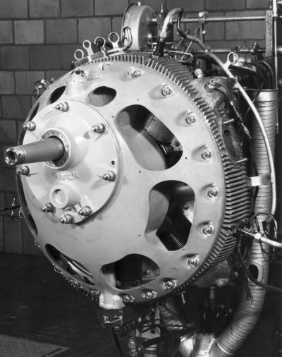 |
The Mawen Bi-Rotary Engine Residing in the Aviation Museum of Kentucky aircraft engine collection is an unremarkable appearing engine that’s about the size of a bushel basket. It is a Mawen engine, and it represents what was possibly the ultimate in aircraft rotary engine design. Mawen was one of several concerns in the 1930s that had purchased the patent rights for the a class of engines invented by Ignacz Sklenar of Hungary. Sklenar applied for a patent for his first bi-rotary engine on 19 May 1914. A bi-rotary is a type of rotary engine with relative motion between a cylinder row and an encircling annular valve member. With Sklenar’s 1914 bi-rotary design, the crankshaft and cylinder row were geared so they rotated in opposite directions at different speeds. Sklenar also left off the tops of the cylinders and the entire rotating cylinder row was encased in a fixed ring. The inner surface of the ring thus formed the tops of the cylinders and had sliding valve intake and exhaust ports and spark plugs built into it. As the cylinder row rotated, each cylinder in turn passed the appropriate stations on the ring for normal four stroke operation. Believing that the bi-rotary engine had potential for use in both military and general aviation aircraft as well as possible automotive applications, Mawen initiated a series of engineering tests to refine the design. By 1938, a seven cylinder Mawen engine of 75 hp and a nine cylinder engine rated at 175 hp had passed French Air Ministry tests and a development contract for three engines of about 1,000 hp had been secured. Development efforts were also simultaneously taking place in the United States. In July of 1937, Professor Andre J. Meyer had signed a contract with Mawen to serve as a consultant. Meyer and his team made improvements to the design, construction, lubrication and durability of the engine. |
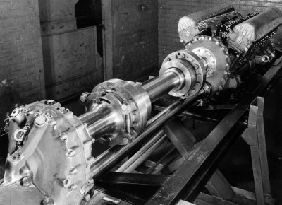 |
"Gearing for Gearheads" Redux I recently received a copy of "Progress Report, Reduction Gears U.S. Ratio, New Tooth Form for Increased Capacity", issued by the Packard Motor Car Company in July, 1943, describing tests of Rolls-Royce Merlin 20° and 25° gear tooth forms. Naturally this occurred right AFTER Parts 1, 2 and 3 of "Gearing for Gearheads" had appeared in Torque Meter (Vol. 5, Nos. 1, 3 and 4) and on the AEHS web site. The analytics of "Gearing for Gearheads", it turned out, was supported by the Packard report with surprisingly sharp coincidences of result and practice. The Packard test set-up followed the nearly universal industry practice of "motoring" two gearboxes of identical ratio coupled input to input and output to output on what amounted to a dynamometer chassis. A constant torque was maintained between the input couplings of the two gearboxes by a twisted torsion bar. The two gearbox output couplings were connected by a torsionally rigid shaft assembly that allowed adjustment of the relative angle between the two output shafts. Test preparation involved preloading the output shaft by "winding" the input coupling torsion bar to introduce the torque required for the particular test. The angular twist in the torsion bar was read by virtue of a fixed degree wheel at one end of the torsion bar and a torsionally unloaded and tubular concentric member indexed at the other end and reaching to the degree wheel to provide a cursor marking. |
