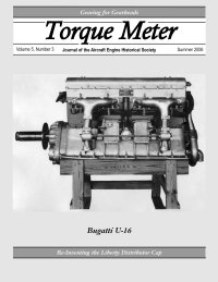
Torque Meter
Summer 2006 Issue
 |
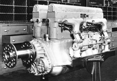 |
The U-16 Revisited The Bugatti U-16 aero engine of WWI has not had a good press. It never entered service and even on the ground it was responsible for the first US casualty of the war. Griffith Borgeson was particularly critical, calling the engines "scrapheaps in the sky". I believe that he was wrong. WW1 fighter development by both combatants led to a horsepower race, with the jewel-like but inherently limited rotaries overtaken by heavier and more powerful fixed multi-cylinder units. At the same time a specific fighter requirement arose for an engine which could carry a machine gun firing through the centre of the propeller. Interrupter gears allowing one or even a pair of machine guns to fire through the propeller disc were more reliable that one might expect, but nobody — least of all the pilots — had unlimited faith in them. In practical terms this meant a geared engine, with a gun carried above the crank line and firing through the second reduction gear and propeller hub. Birkigt solved the problem with his elegant Hispano moteur-canon, and Bugatti was slightly too late to patent the same approach. |
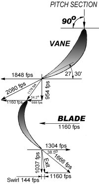 |
An Introduction to Turbine Blading Evolution of aircraft propulsion has resulted in many different apparatus and approaches; and as it has evolved over the past 100 years, turbines have become ever more prominent. Examples include turbo-superchargers, power recovery turbines, turbojet engines, and even turbine powered pumps for rockets. These simple spinning turbine wheels hide the complexity of what it is that makes them go. This article is intended to remove some of the mystery and provide an appreciation for what a properly shaped single moving part can do. Directing a spray of water upon a lawnmower wheel, causing it to spin rapidly, demonstrates the principle of a turbine. "Gas turbines", the type usually encountered in aviation, exploit these same forces, though the power to drive the turbine comes from hot pressurized gas. When this gas expands to a lower pressure some of its contained pressure and thermal energy is converted to velocity, and when directed onto a properly shaped turbine blade, will do work, and produce power. Most jet engines have a turbine for the simple purpose of driving the compressor, which is working to compress the air needed to develop thrust in a jet nozzle. This compression work shows up as heat in the air, and by subsequently burning fuel in the air, the gas temperature is further increased, providing an excess of energy in the exhaust gas that can be expanded through a nozzle to produce propulsive thrust. No matter what the turbine drives, the fundamentals of the processes occurring within the turbine blade passages are the same. |
|
Aero Engine Drawings by Frank Munger |
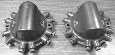 |
Re-Inventing the Liberty Cap, Part 1 Kip Motor Company began operations by purchasing and reselling parts. As years went by, many of the parts we had been selling on a regular basis started getting very difficult to source, as original and aftermarket manufacturers began rationalizing product lines and obsolete stocks were depleted. It was a crossroads; either we abandon our primary market and find a new line of business, leaving thousands of customers and vehicles with virtually no dependable source of essential spares, or we could develop creative ways of economically producing high quality parts in very tiny quantities. Stubborn, or just plain foolish, we chose the latter path, and today Kip Motor Company manufactures over 50% of the products we sell. Once the path had been chosen, we never looked back. Over the years we’ve developed a unique method of thinking and through it developed small batch production techniques for almost any part fitted to a motor vehicle, from plastics and metal castings to stampings, rubber moldings, engine and brake components, interior kits and etc. Many of our techniques required research and re-invention of old technologies long ago discarded by modern production facilities. Such was the case with the Liberty cap. |
 |
Gearing for Gearheads, Part 2 The geometry, tooth forms, ratios and dimensions of production as well as modified gearsets for the Rolls-Royce Merlin propeller speed reduction unit (PSRU) were presented in Part 1. We’ll now explore the basic features and relations of involute spur gearing. These can be found in textbooks and references but not all in one place or in generally convenient forms. Many textbook presentations are aimed at accommodating the design of a gear train using standard momentarily popular tooth forms. They accordingly often contain constants and assumptions that prohibit their direct use in "reverse engineering" a gearset like the R-R Merlin’s, which was at the cutting edge of technology when it was designed. We hope the results will be useful to AEHS Gearheads beyond study of the R-R Merlin PSRU. |
