


Japanese Engines
Regulations for Acceptance Testing of Japanese Aircraft Engines
Images and Data Courtesy of Rob Mawhinney
 |
 |
 |
 |
 |
 |
 |
 |
| Unified Type #: Ha51-01 | Branch of service: Army | Old Army Type #: Ha51 |
|---|---|---|
| Popular Name: 22cyl Homare | Type: Air-Cooled 22-Cylinder 2-Row Radial | Displacement: 2,673 in³ (43.8L) |
| Takeoff HP: 2,450 | Rated HP at Altitude: 1,950 @ 8,000m | Takeoff RPM: 3,000; Rated RPM: 3,000 |
| Manifold Pressure, Takeoff: +450; Rated: +400 | Compression ratio: 6.86:1 | Supercharger Type: 1-Stage, 2-Speed, Centrifugal Clutch |
| Supercharger Ratio(s): Low:6.67:1; High:10.0:1 | Supercharger Impeller Diameter: 330mm | Fuel Metering: Carburetor |
| Prop Reduction Gear: Planetary Spur .420:1 | Dry Weight: 1,000kg | Aircraft use: Experimental, Abandoned |
| Manufacturer(s): Hitachi/Tachikawa A.A.A. | Quantity: 3 (4) built | Dates: 1942~45. 1st full scale engine early 1944. Completed 100hr bench test |
| Special Notes: Problems with high oil consumption. Valve included angle: 62° (Homare: 72°) BMEP - 16.8 | Low Blower Ratomg: 2,400 HP @ 2,000m | Diameter/width: 1.256m |
| Length: 2.000m | Developed from Army Ha45. Fan cooling. Test engine used float carburetor. | Bore: 130mm; Stroke: 150mm |
Ha54-01
| Unified Type #: Ha54-01 | Old Army Type #: Ha505 | Popular Name: 36 cyl Kotobuki |
|---|---|---|
| Type: Air-Cooled 36-Cylinder4-Row Radial | Displacement: 5,895in³ (96.6L) | Takeoff HP: 5,000 |
| Rated HP at Altitude: 4,500 @ 9,000m | Takeoff RPM: ?; Rated RPM:2,500 | Fuel Metering: Low Pressure Fuel Injection with ADI |
| Propeller: Contra rotating | Dry Weight: 1,350kg | Aircraft Use: Design Stage Only |
| Dates: In planning 10/20/43; to be completed in December 1944 | Special Note: Turbosupercharged | Development Notes: Developed from Ha219 (Ha44-12) |
Ishikawajima Tsu-11
 |
 |
 |
 |
 |
 |
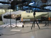 |
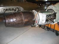
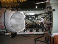
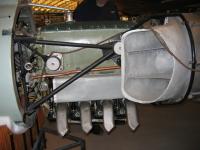
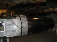
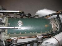
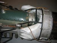
The Tsu-11, a primitive Japanese motorjet engine was produced in small numbers near the end of World War II. It propelled the Japanese Ohka kamikaze weapon.
The Tsu-11 used an air-cooled four-cylinder inverted inline Hitachi Hatsukaze Ha 11 piston engine to drive a single-stage compressor. A fuel injection system supplied fuel that was mixed with compressed air and ignighted, creating thrust. The Ha 11, derived from the license-built Hirth HM 504, had a bore of 110 mm (4.13"), a stroke of 125 mm (4.53") and displaced 3,998 cm³ (244 in³). It weighed 115 kg (253 lb) and produced 82 kW (110 hp)
A single example of a Tsu-11 engine exists at the National Air and Space Museum in Washington, DC, installed in the museum's Ohka 22. Engineering analysis of the engine during the restoration process suggested that the fuel injection and combustion probably contributed little to the power of the engine, with most of the thrust being produced by the compressor
Design Details of the Mitsubishi Kinsei Engine (4.7MB PDF)
by W.G. Owens
The AEHS is indebted to Mr. J.L. McClellan and to the McGraw-Hill Publishing Company for their generosity in sharing this design evaluation of the Mitsubishi Kensei engine. This article originally appeared in the August, 1942 (Volume 41, Number 8) issue of Aviation magazine, published by McGraw- Hill Publishing Company of New York, NY, USA.
It was reconstructed from microfilm by J.L. McClellan. The reconstruction process used by Mr. McClellan is highly labor intensive, using much level stretching, followed by hand touch-up of lines and clean up of extraneous marks, gray areas, and other image defects.
The microfilm was taken from a tightly bound volume, so that there is some distortion of the images, especially near the binding. It has not been practical to remove or compensate for all the distortions, so none of the illustrations in this reconstruction should be considered reliable sources as to fine details of shape, proportion or spatial relationship. The distortions are, in general, small, and should not detract from a general appreciation of arrangement and relationship. Mr. McClellan has attempted to represent the original layout of the article, but there are some exceptions. Limitations in the compositing tools cause a difference in the text flow relative to the illustrations, compared to the original, so that some changes have been made, to compensate partially for that effect, and the tabular data have been removed from the flow of text and brought together on a single page after the text, partly to make them more accessible, and partly to sidestep problems with page layout.
Nakajima Aircraft Industries History
Japanese Engine Research at the National Air and Space Museum
Yokosuka Naval Air Arsenal
YE3B (Ha 74 Model 01) or YE3E (Ha 74 Model 11)
 |
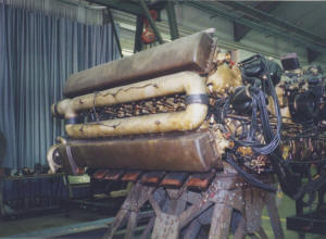 |
| Yokosuka Naval Air Arsenal YE3B or YE3E | Yokosuka Naval Air Arsenal YE3B or YE3E |
Around 1925 to 1930, the Japanese Navy had an interest in and frequently used 12-cylinder, 60 degree angle, liquid-cooled W-type engines such as the 500 shp Model 90 and 600 shp Model 91, both derivatives of the French Lorraine aircraft engine. They were favored because of their high power and low frontal area. In 1934, the Japanese Navy began development of an 18-cylinder, 40 degree angle W-type engine known as the 900 shp Model 94. More powerful versions of this engine were undertaken, including the YE2A which started development around 1937-38 and its derivative, the 2,500 shp, 18-cylinder W-type Ken No. 3 (believed to be the YE2H, also Ha 73 Model 01).
During the mid-1930s, other Japanese organizations, including Mitsubishi, Nakajima, and the Army Air Arsenal had a parallel interest in high power, low frontal area aircraft engines, specifically H-type, 24-cylinder designs. The objective of these designs was to install the engine inside an aircraft wing or fuselage, and thus increase speed. These efforts did not result in a successful engine.
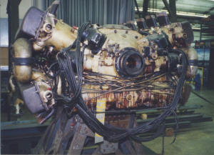
Around 1940, the Navy began development of the YE3A, a 2,500 shp, 24-cylinder, liquid-cooled, X-type engine, which had been derived from the 18-cylinder YE2A and had the same bore and stroke as the YE2H. By October 1943, an experimental 2,500 (or 3,200) shp horizontal X-24 liquid-cooled engine, known as Ken No. 1 (believed to be the YE3B, also Ha74 Model 01), was being developed and tested by the Yokosuka Naval Air Arsenal for internal wing installation. A similar engine for internal fuselage installation, known as Ken No. 2 (believed to be the YE3E, also Ha 74 Model 11), was rated at 3,200 shp and scheduled for completion in March 1944.
This engine type is a YE3 and evidence suggests that it is the Ken No. 1 or YE3B model. The engine had a two-stage reduction gear with an internally splined engine drive shaft. Fitted to this was an extension drive shaft that is believed to have driven contrarotating propellers. The intended airframe application is unknown.
Despite the Yokosuka Naval Air Arsenal's sequential development of and progress with ever more powerful engines, including W-12, V-12, W-18, and X-24 configurations, it could not keep up with the even faster development of high power air-cooled radial engines. None of these high power liquid-cooled engines under development by the Navy reached operational status by the end of World War II. Other nations, including the U.S., had undertaken similar development of "monster" reciprocating engines. However, following the War, the focus of international engine development turned toward turbine engines. Country of Origin: Japan Description: 24 cylinders; 2,500 (or 3,200) hp (estimated); liquid-cooled; fuel injected; manufactured circa World War II; experimental; missing starter, generator, spark plugs, data plate; on stand. Notes: This engine was originally accessioned as "Found in the Collection." Subsequent documentation indicated that the engine was transferred from the U.S. Army Air Forces.
National Air and Space Museum Curatorial Remarks: Interpretation of YE3A, YE3B, and YE3E. The first letter, Y, is the capital of the manufacturer, Yokosuka Naval Air Arsenal. The second letter, E, means liquid cooled. The third number, 3, means the sequence of development beginning from serial number 1. The fourth letter, A, B, and E, means the order of modification of the engine starting from A. Thus, these model designations means the third liquid-cooled engine developed by the Yokosuka Naval Air Arsenal.
Believed to have been transferred to the National Air and Space Museum from the U.S. Army Air Forces, Wright Field, Dayton, Ohio.
Bibliography:
Masayoshi Nakanishi, Story of the Mystery Engines (Unpublished Paper, Japan, June 15 1998).
R. G. Allen, Technical Intelligence Report No. 228, Japanese Aero Engine Data (Revised) (Library Identification: D52.41/9 Misc. Japanese) (TSNTE-3, April 1, 1946), B7-15.
Air Information Branch, Air Information Report No. 4, M. & P. - June 1, 1943, Japanese Engines (Bureau of Aeronautics: Washington, D.C.: June 1, 1943), 11.