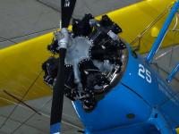
Continental W670 (Wiki)
Continental’s Radial Aircraft Engines
Compiled by Kimble D. McCutcheon
Published 26 Jan 2020; Revised 28 Jan 2020
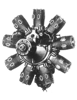
Continental Aircraft Engine Corporation's first aircraft engine appeared at the 1927 Chicago and New York automobile shows. This air-cooled, 9-cylinder sleeve-valve radial apparently used a Wright J-4 crankcase that had been modified to accept cylinders with sleeve valves. With a 4.5" bore, 5.5" stroke, and 787.3 in³ displacement, it was advertised to produce 220 hp at 1,800 rpm, and said to weigh 475 lb. The cylinders were grey iron castings with integral cooling fins. Two exhaust ports faced the propeller, and induction was accomplished by three aft-facing intake ports. The one-piece master rod was captured by a two-piece crankshaft incorporating a clamp on the rear crank cheek. The crankshaft ran on two ball bearings. This crankshaft and master rod construction was a departure from the original Wright Whirlwind practice, and CAE would use it for all its future radials. A centrifugal supercharger was included in the rear crankcase section. Two magnetos, located on the crankcase front section, were driven by a cross shaft geared to the cam ring reduction gearing.[Aerosphere 1939, 229]
According to CAE engineer Carl Bachle, internal clearance problems prevented this sleeve-valve radial from ever running.[2 Dec 1977 Letter, Carl Bachle to Les Waters. Author's Collection.] This engine was not developed further and, of course, never entered production.
 |
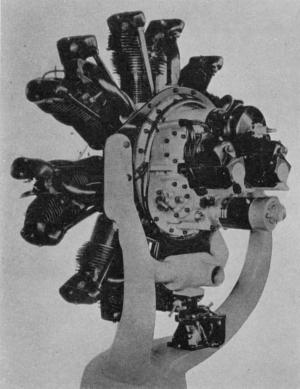 |
| Continental’s First Radial — a Sleeve Valve (Aerosphere 1939) | The 1929 Continental A-70 (Aerosphere 1939) |
The A-70
Continental introduced its first production engine, the A-70, in 1929. A 7-cylinder air-cooled radial with a 4.625" bore and stroke displacing 543.9 in³, the A-70 produced 165 hp at 2,000 rpm on 65 octane fuel and weighed 415 lb. It was awarded Approved Type Certificate No. 32 on 5 Oct 1929. Early engines had a 5.0:1 compression ratio, which was raised to 5.4:1 on the later A-70-2.[Wagner, William. Continental! Its Motors and Its People Fallbrook, CA: Aero Publishers Inc., 1983. 39-42]
Cylinders were constructed from forged barrels, machined all over with integral cooling fins that were screwed and shrunk into cast aluminum alloy heads featuring integrally cast rocker boxes. Aluminum-bronze valve seats and spark plug bushings were used. Intake ports faced away from the propeller while exhaust ports faced toward it. Valves were actuated by fully-enclosed valve gear featuring a double cam ring, tubular duralumin push rods and forged steel rocker arms. Hollow-stem exhaust valves were made of C.N.S. alloy steel; intake valves were made from tungsten steel. Pistons were heat-treated die-castings of aluminum alloy and fitted with three rings above the wrist pin and one below.
A two-piece cast aluminum alloy crankcase was joined on the cylinder plane. The front section supported a ball thrust bearing and roller radial bearing, both in steel sleeves. The rear section supported the rear bearing and featured passages for induction, along with cam follower bores. An aluminum alloy gear case, attached at the crankcase rear, housed accessory drive gearing and provided accessory mounting pads.
The built-up A-70 crankshaft was joined via a bolted clamp, part of the rear crank web. Two roller main bearings and a ball thrust bearing supported it in the crankcase. The one-piece master rod, fitted with a white-metal steel-shelled master rod bearing, carried six link rods. The link rods were secured to the master rod by knuckle pins held in place with locking plates. All rods were H-section alloy steel forgings that were machined all over. Continental rods were true H-section, which, in the structural sense and unlike I-section rods, maintained constant cap thickness. Wright Aeronautical also used this term in a different way, and it has become synonymous with rods whose webs were parallel to the engine centerline; I-section rod webs are typically perpendicular to the engine centerline. Continental used true H-sections whose webs were perpendicular to the engine centerline.
Dry-sump pressure lubrication to all bearings and valve train components was achieved via a gear-type pressure feeding drilled passages, thereby eliminating any exterior oil pressure lines. A gear-type scavenge pump returned oil to the tank.
Two flange-mounted Scintilla MNF7-DF magnetos provided ignition. A single-barrel Stromberg NA-R6 or Holley 419 carburetor fed fuel-air mixture to a horseshoe-shaped manifold via two inlet pipes. Steel tubes connected the manifold to the cylinders.[Aerosphere 1939, 229; FAA Type Certificate ATC32]
General Aircraft Corp. of Buffalo, New York used the first production A-70 in its Aristocrat G-102-F cabin monoplane. A-70s were also sold to Verville, Waco and others. In all, over 100 A-70s were produced.[Wagner, 52]
The R-670
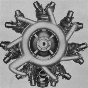
An enlarged and improved version of the A-70, Continental’s R-670 produced 210 hp at 2,000 rpm on 66 octane fuel, and at 425 lb, weighed only 10 lb more than the A-70. The R-670 featured a 5.125" bore, a 4.625" stroke and a 667.9 in³ displacement. Compression ratio was 5.4:1 and installation dimensions were identical to the A-70. R-670 cylinder heads had an improved fin pattern. Aluminum alloy pistons were made in permanent molds and were equipped with a wider (0.188") oil ring fitted to the third groove, with a standard compression ring serving as an oil scraper and located below the piston pin. Both link rod ends were enlarged, valve areas increased and valve springs improved. A Stromberg NA-R6 carburetor fed enlarged inlet passages and Scintilla MN7-DF magnetos furnished ignition.[Aerosphere 1939, 233-234, FAA Type Certificate ATC80] The R-670 first flew in the company Waco F-2 on 14 Dec 1931. [Wagner, 52]
The R-670 received Approved Type Certificate No. 80 on 21 Aug 1933, which was later revised to include R-670A, R-670-C, R-670-E and R-670-G models. The R-670-E and R-670-G featured aft-facing exhausts. Later models R-670-B, R-670-D, R-670-F and R-670-H, rated at 225 hp at 2,000 rpm with a 6.0:1 compression ratio and requiring 80 octane fuel received Approved Type Certificate No. ATC120 on12 Feb 1934. The R-670-B and R-670-F models retained forward-facing exhausts, while the R-670-D and R-670-H featured aft-facing exhausts.[Aerosphere 1939, 233-235, FAA Type Certificates ATC80 and ATC120]
 |
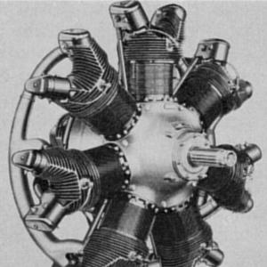 |
| The R-670 (Aerosphere 1939) | The R-670-H (Aerosphere 1939) |
The W670
Sometime between 1934 and 1936, Continental changed the designation on its radial engines from R-670 to W670 (also W-670) and received Type Certificate No. 162 on 27 Jul 1936. Engine models described by this type certificate form the basis of WWII-era military engines and modern engines. These engines were very similar to the earlier R-670 series, sharingthe same 5.125" bore and 4.625" stroke. All were direct-drive, had SAE No. 20 propeller shafts and Bendix-Stromberg carburetors. They were equipped with Scintilla ignition with the right magneto firing at 32° BTC and the left at 29° BTC. Those equipped with battery ignition and distributors were timed at 5° BTC. One new feature that was to prove troublesome in service was the substitution of ball bearings for the roller bearings on the crankshaft mains. The W670 powered numerous aircraft types including American Airmotive NA-75, Boeing-Stearman PT-17 and N2S, CallAir Model A, Cessna 190, Eagle Aircraft Eagle 220, Fairchild PT-23, Funk F-23, G class blimp, Grumman G-164, Kellett K-2A and K-4, Morane-Saulnier MS.317, Timm N2T, Waco 240-A, UEC, UIC, UKC, UKC-S, UKS, VKS, UOC, VQC, UBA, ULA, UBF, UMF and UPF.
| W670-6A | W670-6N | W670-16 | W670-K | W670-M | W670-23 | W670-24 | |
| Normal and Takeoff Rating (hp @ rpm) |
220 @ 2,075 | 220 @ 2,075 | 220 @ 2,075 | 225 @ 2,175 | 240 @ 2,200 | 240 @ 2,200 | 220 @ 2,075 |
| Minimum Fuel Grade |
65 | 65 | 65 | 65 | 80/87 | 65 | 65 |
| Compression Ratio |
5.4:1 | 5.4:1 | 5.4:1 | 5.4:1 | 6.1:1 | 5.4:1 | 5.4:1 |
| Weight, Dry (lb) |
470 | 479 | 486 | 450 | 455 | 519 | 492 |
| Bendix-Stromberg Carburetor |
NA-R6, NA-R6D | NA-R6, NA-R6D | NA-R6G | NA-R6D | NA-R6D | NA-R6G | NA-R6G |
| Venturi Diameter (inches) |
1-15/16 | 1-15/16 | 1-15/16 | 1-15/16 | 1-15/16 | 2-1/16 | 1-15/16 |
| Scintilla Ignition | VMN7-DF Magnetos, WL7A Battery Ignition, or Magneto and Battery Combination | SF7R-1 Magnetos | SF7R-1 Magnetos | MN7-DF Magnetos or WL7A Battery Ignition, or Magneto and Battery Combination | MN7-DF Magnetos or WL7A Battery Ignition, or Magneto and Battery Combination | VMN7-DFa Magnetos, WL7A Battery Ignition, or Magneto and Battery Combination | VMN7-DFA Magnetos or WL7A Battery Ignition, or Magneto and Battery Combination |
| From Type Certificate No. 162 | |||||||
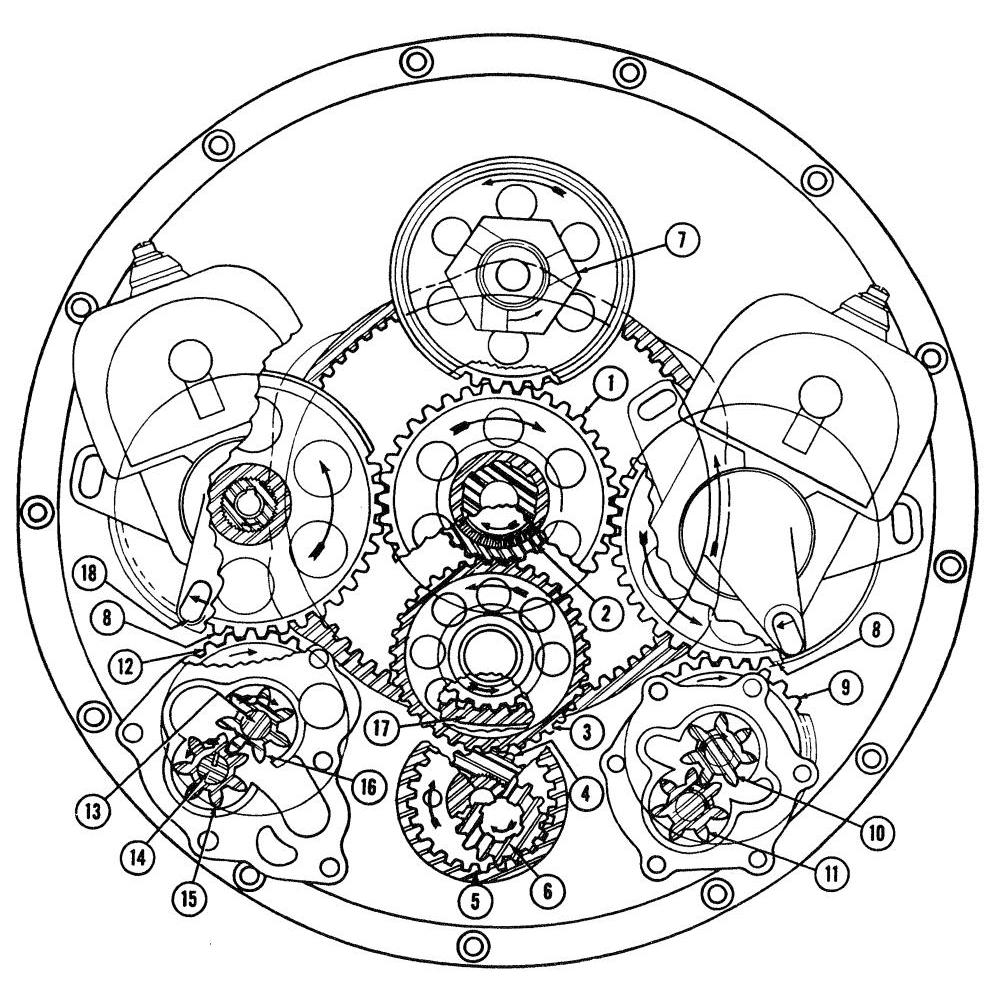 |
| Reference | Gear | Rotation | Crankshaft Ratio |
| 1 | Rear Crankshaft Starter Gear | CW | 1:1 |
| 2 | Cam Ring Bearing Gear | CW | 1:1 |
| 3 | Intermediate Cam Drive Gear | CCW | 0.1667:1 |
| 4 | Generator Step-Up Drive | CW | 1.2:1 |
| 5 | Generator Drive Gear | CW | 1.2:1 |
| 6 | Generator Final Drive Pinion | CCW | 1.95:1 |
| 7 | Starter Gear | CCW | 1:1 |
| 8 | Magneto Drive Gears | CCW | 0.875:1 |
| 9 | Rocker Scavenge Oil Pump Driving Gear | CW | 1.25:1 |
| 10 | Rocker Scavenge Oil Pump Drive Gear | CW | 1.25:1 |
| 11 | Duplex Oil Pump Driving Gear | CW | 1.25:1 |
| 12 | Duplex Pressure Oil Pump Drive Gear | CW | 1.25:1 |
| 13 | Duplex Pressure Oil Pump Driven Gear | CCW | 1.25:1 |
| 14 | Duplex Pressure Oil Pump Driven Gear | CCW | 1.25:1 |
| 15 | Duplex Scavenge Oil Pump Drive Gear | CCW | 1.25:1 |
| 16 | Duplex Scavenge Oil Pump Driven Gear | CW | 1.25:1 |
| 17 | Cam Ring Gear | CCW | 0.1667:1 |
| From Type Certificate No. 162 | |||
W670s for the Military
In a 17 Mar 1936 meeting with the Air Corps, Continental Chief Engineer Norman N. Tilley stated that his company was redesigning the R-670 engine, incorporating many changes that would make an attractive training engine.[20 Mar 1936 Memorandum Report E-57-285-30, P031224 (U.S. National Archives Record Group 342, Finding Aid UD, Entry 1002-A, Box 5, Power Plant Laboratory Microfilmed Memorandum Reports, Reel 3, Frame 1224)]
The U.S. Army Air Corps Materiel Command Engineering Division Powerplant Laboratory (PPL) conducted a Type Test on a Continental R-670-1 (W670 Series 6, SN 5002) starting 7 Apr 1937. Calibration runs, consisting of full-throttle and constant-power mixture control runs, were made before the actual type test began. Torsiograph data were collected using the proposed McCauley flight propeller. At 12 hrs elapsed time, the exhaust collector ring, several exhaust stacks, and the nose cowl had failed. These were repaired, but the exhaust collector broke again at 19.25 hrs on 19 Apr. Testing was suspended and the engine was stored. Testing resumed on 17 Dec 1937, but the nose cowl support brackets broke three more times. Finally, on 27 Dec 1937 at 67.75 hrs the propeller hub broke, releasing a blade. The ensuing imbalance threw the engine off the test stand and completely wrecked the engine.[31 Aug 1939 Memorandum Report E-57-1447-1, P052264]
In a 30 Dec 1937 meeting with Tilley, PPL suggested that it acquire another R-670 for type test since the pervious engine had failed after a government-furnished propeller broke.[05 Jan 1938 Memorandum Report E-57-285-71, P031120]
On 8 Feb 1939 the Air Corps recommended the R-670-3 as a standard equipment item.[8 Feb 1939 Memorandum Report E-57-1824-2, P070760]
The revised R-670-5 oil pumps incorporated a hole in the driving shaft with a spring-loaded ball check valve, a bronze bushing for the pressure relief plunger, a lighter relief spring, a smaller-diameter relief plunger. PPL tested four of the revised pumps, found leakage satisfactory, but recommended the relief valve guide be changed to prevent relief valve cocking.[9 Nov 1940 Memorandum Report EXP-M-57-503-243, P121591]
In a 24 Jan 1942 meeting between Continental and PPL, Continental stated that production engines were being changed to combat numerous thrust bearing and thrust bearing liner failures in R-670-5 engines. These changes include additional axial thrust bearing and replacement of the magnesium thrust bearing cover with an aluminum alloy one. Continental was to publish a service bulletin on this subject.
Magneto drive failures were also discussed. PPL observed that the general design, which employed a tapered magneto shaft, a sharp-cornered keyway in the coupling, and very sharp magneto drive gear and coupling serrations, was a poor design. Three different magneto drive coupling materials had been tried and the problem persisted. PPL observed that the tapered magneto shaft subjected the coupling to extreme stress when the magneto shaft nut was tightened, and further observed that the R-670-4 Navy engine, which used a Scintilla SF7RN magneto (instead of the R-670-5's Scintilla V-MN7DF), had exhibited no magneto drive problems and insisted that Army engines be changed accordingly.[27 Jan 1942 Memorandum Report U-EXP-M-57-7780-1, P180474]
Several military models were ultimately approved and built in quantity. Some of these were converted to civilian use.
| Military Model |
Corresponding Certificated Model |
Carburetor | Magneto | Miscellaneous |
| R-670-3 | W670-6A | NA-R6 | VMN7-DF or MN7-DF |
R-670-3 model, early type oil pump, crankcases, accessory case, and cylinders. |
| R-670-4 | W670-6N | NA-R6 or NA-R6D |
SF7RN-1 or SF7R-1 |
R-670-4 identical to W670-6N. |
| R-670-5 | W670-6A | NA-R6 or NA-R6D |
VMN7-DF | R-670-5 identical to W670-6A. |
| R-670-11, R-670-8, R-670-11A |
W670-16 | NA-R6G | SF7RN-1 | R-670-11 identical to W670-16. R-670-8 and R-670-11A same except have 7th order torsional damper. |
| W670-6N | NA-R6D | SF7R-1 or SF7RN-1 |
Late type engine with latest type crankcase, accessories section, etc. differs mainly from W670-6A in accessories section. | |
| From Type Certificate No. 162 | ||||
Fuel-Injected W-670s
The W-670M-1 received Type Certificate No. TC168 on 4 Nov 1936. This engine was nearly identical to those covered by No. 162 except that instead of a carburetor it had a Marvel CA-7 fuel injection system and produced 250 hp at 2,200 rpm on 80 octane fuel with a 6.0:1 compression ratio. A similar engine, the W-670K-1 produced 230 hp at 2,200 rpm on 65 octane fuel and a 5.4:1 compression ratio. Dual Scintilla MN7-DF or MN7-DFA magnetos, WL7A-CLW battery ignition, or a magneto with battery ignition furnished ignition. Dry weight was 460 lb for magneto ignition, 463 lb for battery ignition and 470 lb for magneto/battery ignition.[Wagner, 52, Type Certificate No. 168]
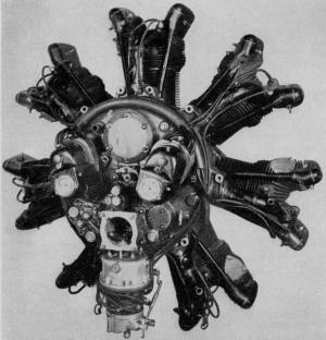 |
| The Fuel-Injected W670M-1 (Aeroshpere 1939) |
Experimental Sleeve-Valve Radials
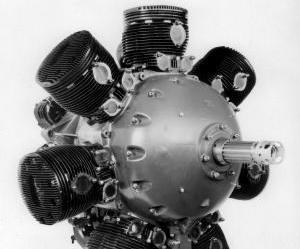
Continental acquired world rights to the Burt-McCollum single-sleeve valve in Apr 1926. Starting on 16 Jan 1930, Continental began a series of experiments for the U.S. Navy that culminated in the R-794, a 7-cylinder sleeve-valve engine weighing 577 lb that produced 411 hp @ 2,220 rpm. Although the engine met performance expectations, it was never reliable and never entered production. Navy finally cancelled the project in late 1935.
From 1935 until 1938, Continental endeavored to produce a 14-cylinder sleeve-valve engine. The resulting R-1740, delivered in 1941, had a 800 hp @ 2,500 rpm takeoff rating, weighed 1,338 lb. Again, it was never reliable and never entered production.[McCutcheon, Kimble D. America’s Sleeve-Valve Aircraft Engines. Unpublished Manuscript]
 |
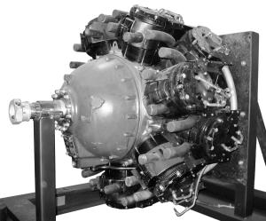 |
| R-794 Sleeve Valve Radial (Author) | R-1740 Sleeve Valve Radial (Author) |
Continental Radials in Armored Vehicles
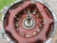
The W670-9A was similar to other W670 models and used most of the same components. Intended for use in light armored vehicles, it had a larger front crankshaft journal and thrust bearing, and a drive scheme suitable for a clutch rather than a propeller. It powered the T2, T4 and M1 Combat Car; M2 Light Tank; M3 Stuart; LVT-2, LVT-4, LVT(A)-1, LVT(A)-2, LVT(A)-4 and LVT(A)-5 Landing Vehicle Tracked.
License-Built Engines
Continental built 9-cylinder Pratt & Whitney R-1340 engines under license during WWII; these powered North American AT-6 and SNJ advanced trainers. Continental also built 9-cylinder Wright Whirlwind 975EC2 tank engines under license. Variations developed between 340 hp @ 2,400 rpm and 400 hp @ 2,400 rpm. This engine powered the M2, M2A1, M3, M3A1, M3A2, M3A5, M4A1, M4, M4A1(76)W, M4(105), M7, M39, M44, M4A1(76)W HVSS, M4(105) HVSS, M18, and M7.
Air Repair
On 25 Aug 2011, Air Repair, Inc. of Cleveland, Mississippi acquired Type Certificate No. 162 and began making new parts for the W670. Air Repair changed the crankshaft main bearings from ball to roller type, modernized the seal and gasket materials, and provided for draining oil from the #4 intake tube. Air Repair can salvage worn crankshafts by plating and offers overhauled engines with either steel or Nu-Chrome cylinders. Nearly all components in a W670 overhauled by Air Repair, except for the crankcase, crankshaft, master rod and cylinders, are new.[18 Jan 2020 Telephone interview with Air Repair spokesperson]
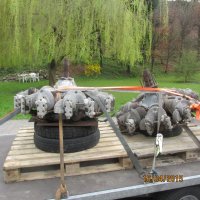
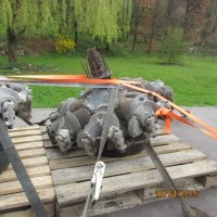
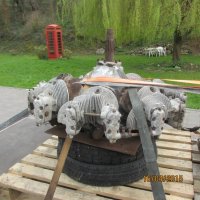
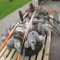
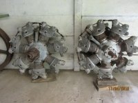
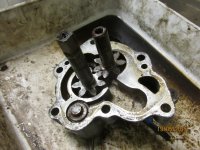
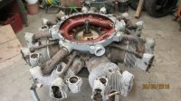
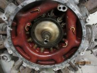
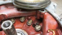
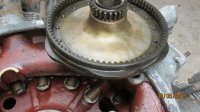
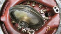
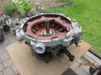
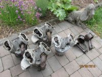
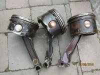
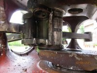
AEHS Member Roland Servais from Belgium has restored a W670 to running condition. He began with two engines. One had a wrecked crankcase and connecting rods, possibly due to starting with a hydraulic lock. The second engine had light exterior damage. Salvaging parts from each, he managed to build a complete running engine.
 |
 |
 |
 |
 |
| Engines Arrive | ||||
Wrecked Engine Disassembly
 |
 |
 |
 |
 |
 |
| Oil Pump | Accessory Housing | Aft Crankcase | Aft Crankcase | Tappets | Cam |
 |
 |
 |
 |
 |
 |
| Cam | Accessory Housing | Cylinders | Wrecked Pistons, Rods | Wrecked Master Rod | Aft Crankcase |
Second Engine Disassembly
Reassembly
W670 Running (Video 1 ,Video 2)