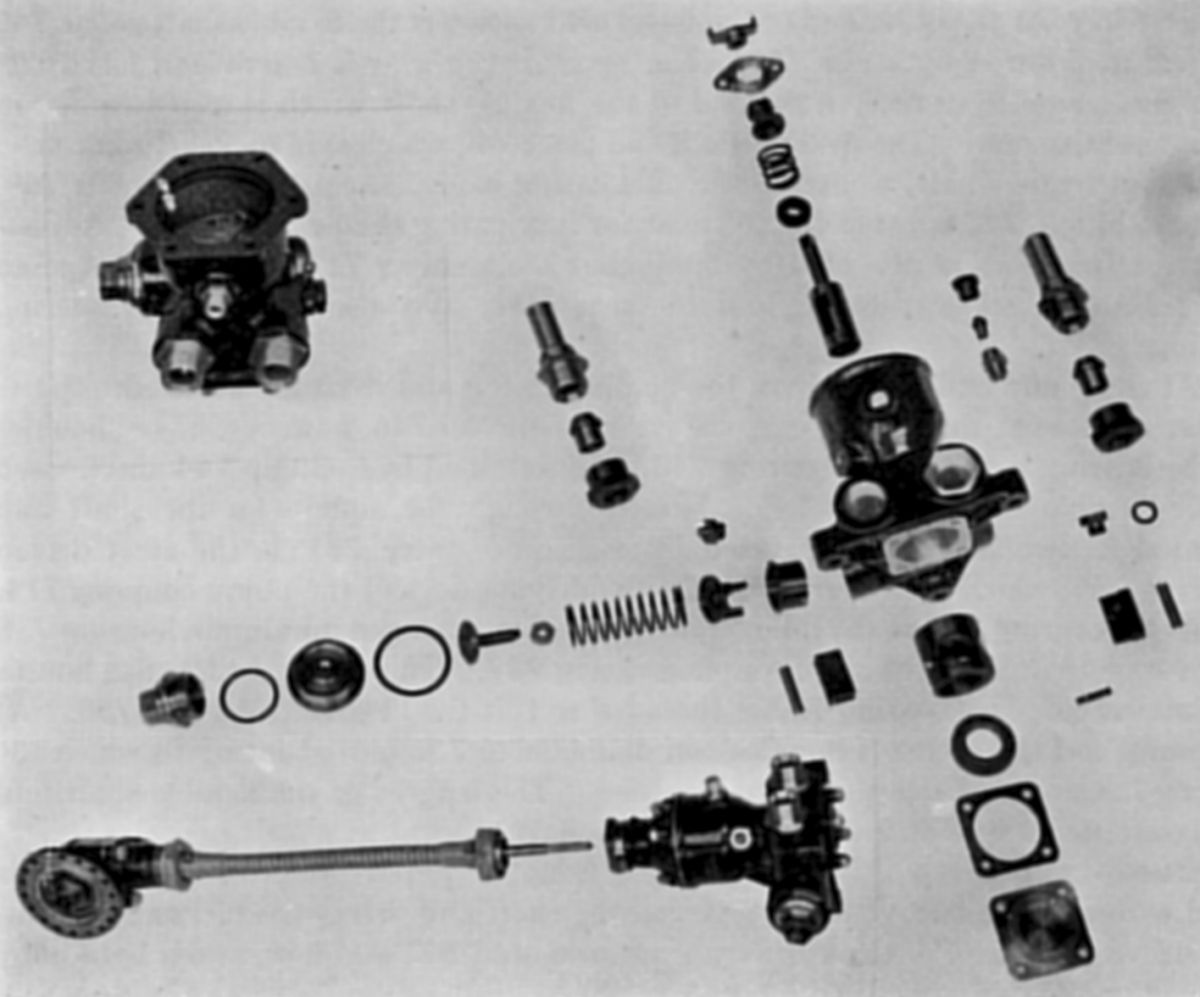
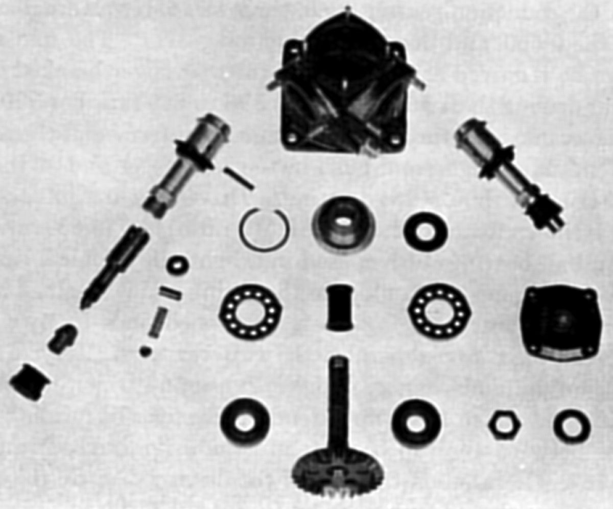
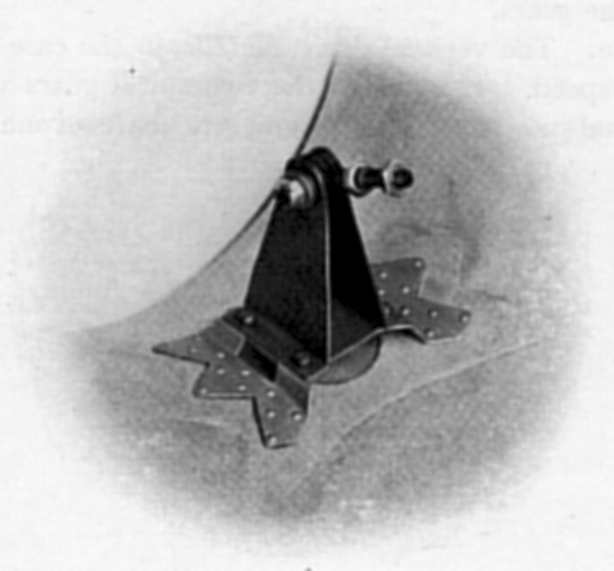
Flexibly-Driven Pump Dismantled
Bristol Pegasus II.L and II.M
General Engine Accessories
Fuel Pump and Tach Drive,
Gas Distributor,
Generator Drive,
Gun Gear,
Exhaust Ring,
Air Intake,
Inter-Cylinder Baffles,
Priming System,
Fuel and Oil System Installation
Compiled by Kimble D. McCutcheon
Published 09 Feb 2025
| Part 1: Specifications | Part 2: Description |
| Part 3: Supercharger, Lubrication | Part 4: Accessories |
| Part 5: Magnetos | Part 6: Carburettor |
| Part 7: Automatic Throttle Control | Part 8: Starter |
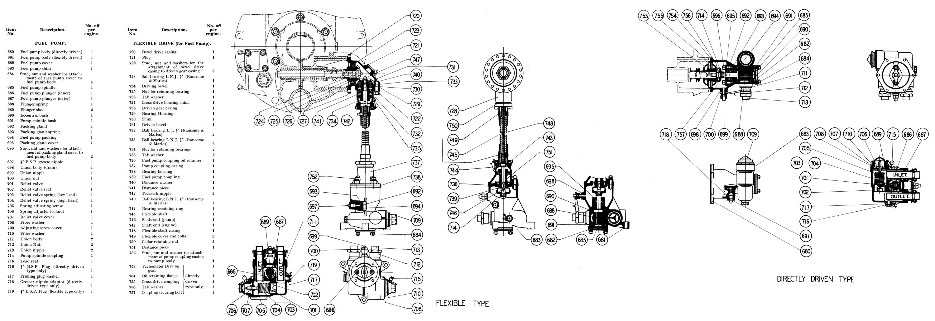
Fuel Pump and Tachometer Drive
|
|
| Fuel Pump and Flexible Drive. Directly-Driven Pump Top Left; Flexibly-Driven Pump Dismantled |
|
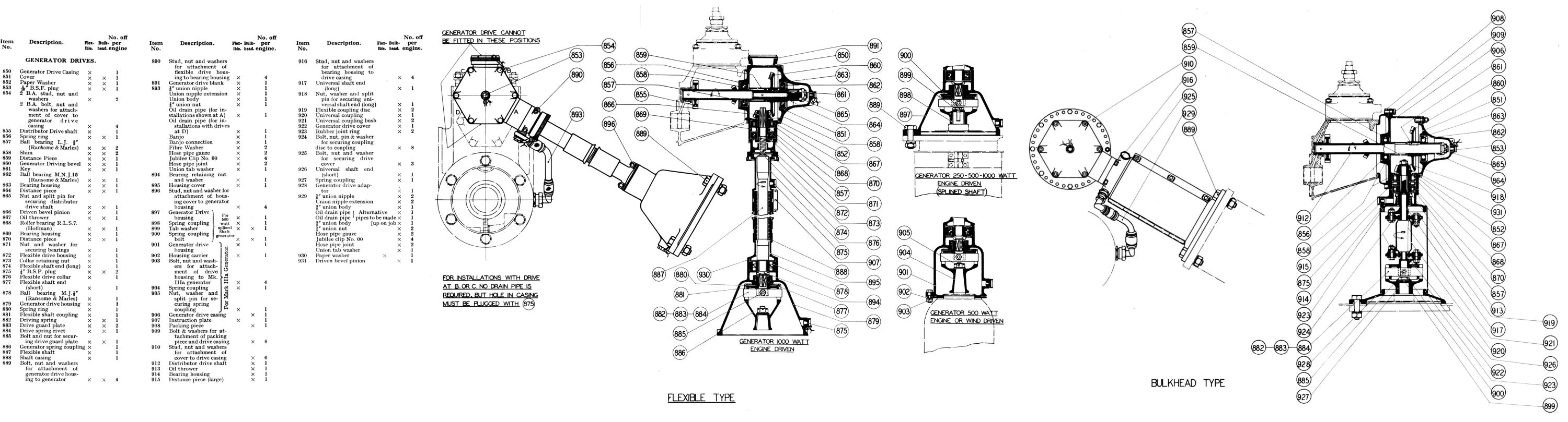
The Bristol vane type fuel pump with its integral relief valve was attached by a six-stud facing to the rear cover right side, and was driven from a cross drive shaft extension. In special cases where it was necessary to have the pump in some other position, a flexible drive could be used, but the directly driven pump was preferred. Both the directly and the flexibly driven pumps were driven at engine speed and rotatef in a clockwise direction looking on the pump driving end.
The Directly Driven Fuel Pump was driven from the cross drive shaft end. The tachometer driving gear, with an integral oil thrower, was freely mounted on the shaft, and was driven by dogs in the sleeve of a second oil thrower, which was keyed to the cross drive shaft. Interposed between the two and secured by a six-stud facing on the rear cover was an oil retaining flange. The flange and the throwers helped prevent oil leakage into the pump. They were, however, not required for the flexibly driven pump, which requied an oil feed that will be discussed later. A coupling bolt with a spigot, blanked off the cross drive shaft oil feed hole. At the rear of the second thrower, an integral collar was formed having two slots that engaged the fuel pump spindle loose driving coupling. The drive was housed in the fuel pump body forward extension, an aluminium alloy casting that contained the pump proper and relief valve. This spigoted on the oil retaining flange and was secured by six studs.
The pump spindle, driven by the loose coupling, passed through a spring-loaded cork gland with the spring positioned by a flanged retainer and the phosphor-bronze packing gland. Emerging from the gland, the spindle diameter was enlarged and was slotted to receive the pump vane. The enlarged portion inner end ran in a phosphor-bronze bearing, which also served as the eccentric housing for the pump vane, while the outer end ran in a white-metal bearing spigoted and dowelled to the pump cover. The vane consisted of two bronze plungers, with a spring captured between them; steel shoes positioned in the plungers rotated in the bronze eccentric housing. The pump inlet and outlet were located on either side of the eccentric housing, and were in the form of stack pipes with a union nut and nipple attached. The top of the pipes extending above the pump proper ensured that the pump was always primed. The relief valve was ccommodated in a separate chamber at the pump body top. A stainless steel seat was inserted in the casting, and a stainless steel valve located on it. Two relief valve springs were supplied with the pump, one of which was suitable for a low tank installation having a head of fuel up to about 11 ft; the other was for a high tank positions up to about 16 ft. An adjuster cap that positioned the spring at its outer end was screwed into an adjuster cover and the adjuster stem was protected by a blank. The pump spindle gland was greased by a lubricator fitted at the body side, while a drain connection to atmosphere was provided at the casing bottom for any oil or fuel that got past the retainers or gland.
The Flexibly Driven Pump used with the flexible drive was practically identical with directly driven pump. The chief difference was in the body itself, which had a four-stud instead of a six-stud facing to suit the drive casing. There were also three extra bosses cast on the body for attachment to the engine bulkhead. The drive was taken from the cross drive shaft in the rear cover. As previously mentioned, the oil throwers used on the directly driven pump were not required because an oil feed was necessary for the bevel gears. These were therefore replaced by a tachometer driving gear without a thrower, which was driven by the bevel driving gear keyed to the shaft. The gear was secured to the shaft by a flanged nut drilled to form an oil feed, and replaced the blanking set screw of the engine driven pump. The gear ran in a ball bearing located in a light alloy housing attached to the rear cover by a circular flange that was drilled so it could be assembled at the most convenient angle. The gear casing underside was formed into a three-stud facing and had a duralumin bearing housing located in it. The driven bevel gear was mounted on two bearings, the larger of which was positioned in the housing just mentioned, while the smaller (at the gear's outer end) was located in the driven gear casing. An oil thrower disc was positioned etween the gear shoulder and the bearing, and a distance piece placed between the two bearings had a collar with a right hand spiral that served as a second oil thrower. The bearings and the oil throwers were secured to the bevel gear by a nut and tab washer. At the bevel gear casing outer end was the flexible shaft collar, retained in position by a nut. The bevel driven gear was hollow and had at its inner end a square to receive the flexible shaft end, which was also steadied in the gear bore. The flexible shaft end piece, made of nickel chrome steel, was sweated to the shaft, while the flexible casing was also sweated to the collar. A grease nipple for lubricating the flexible shaft was fitted to the collar. Gear clearance adjustment was provided by laminated brass shims between the bevel gear casing and the rear cover and also between the bearing housing.
At the flexible casing and shaft drive's pump end were sweated to parts similar to those at the driving end, the pump shaft end, but this one had a shoulder for the bearing location; the bearing was retained by a circlip and housed in the flexible casing cover. Driven through the square on the shaft and mounted in two bearings separated by a distance piece, was the steel driven coupling, which was slotted to engage the pump coupling driving dogs. The larger bearing at the inner end was located in a flanged duralumin housing that spigotsed in the light alloy coupling casing. This casing, which also housed the smaller coupling bearing, was threaded to fit the flexible collar nut. At the pump end the casing diameter increased to a four-stud facing to which the bearing housing and the pump were attached. The flexible shaft and casing were made to length for each individual installations.
If a fuel pump was not required the cross drive shaft was fitted with a sleeve that was keyed to the shaft and drove the tachometer gear. The sleeve was secured to the shaft by a nut and stud, and a light alloy cover enclosed the end.
Tachometer Drive. Mounted in the crankcase rear cover above the oil feed connection, and secured by two screws was the magnesium tachometer casing. It was threaded at its outer end to take a standard connection. A steel tachometer shaft ran in the casing and had a phosphor-bronze thrust washer between its head and the casing. The shaft bore was hollow and was reduced at the centre to a square section for the drive connection. Pinned to the shaft inner end and engaging a gear on the cross-drive shaft was the tachometer driven gear. It ran at 1/4 engine speed and its direction was anti-clockwise when viewed from the engine rear.
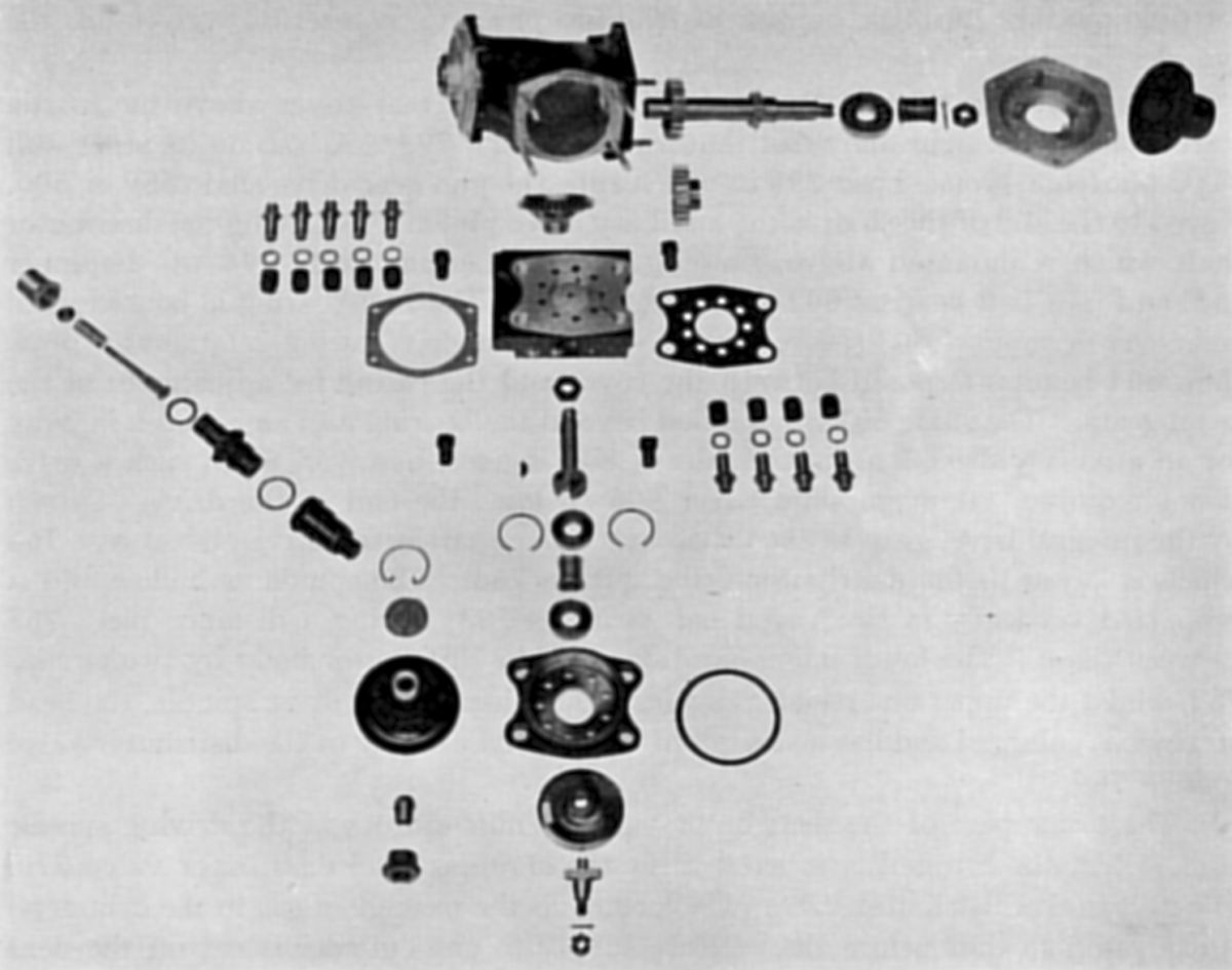
Gas Distributor and Drive
 |
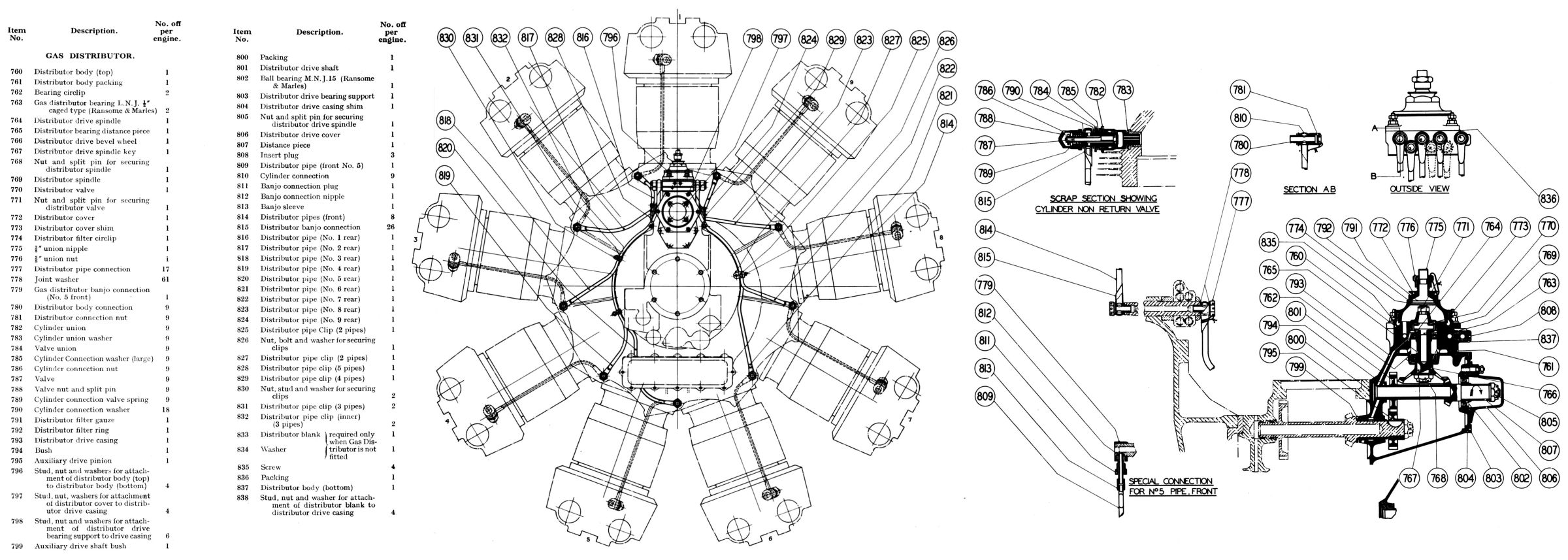 |
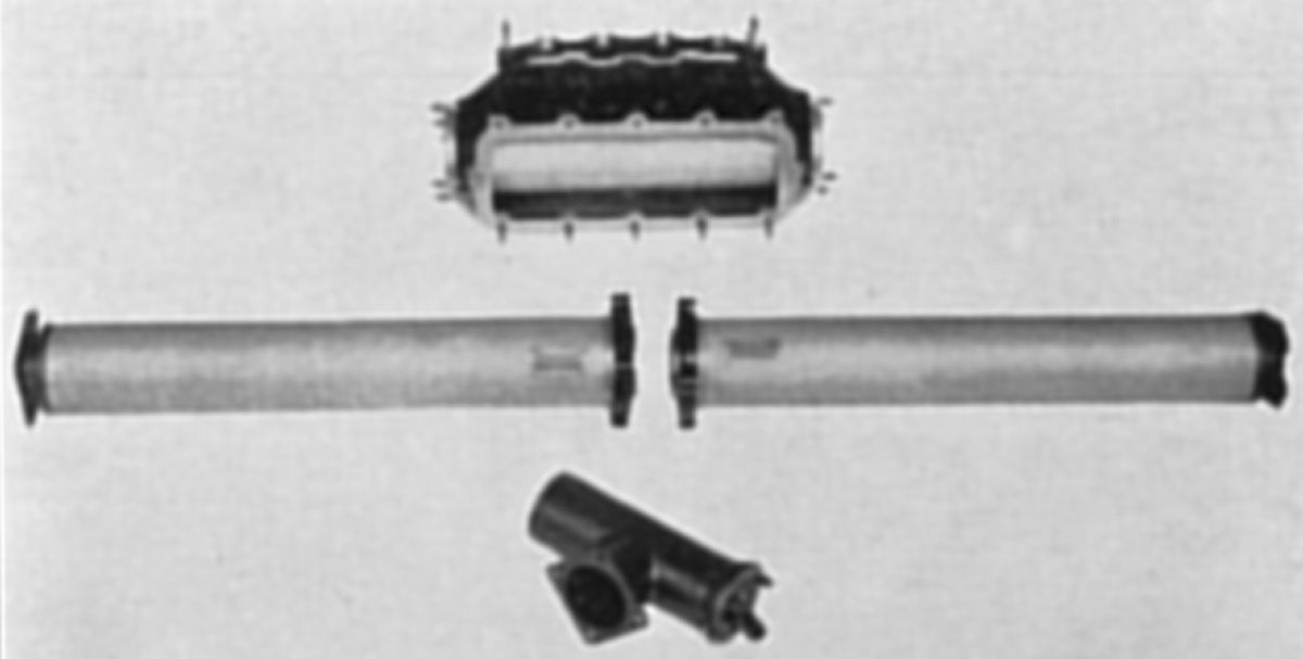
| Gas Distrubutor and Drive | |
The Gas Distributor and Drive was attached to the rear cover above the inertia starter and delivered the starting mixture through copper distributor pipes to check valves in the cylinder head. The light alloy distributor drive casing had a boss on its inner wall and a phosphor-bronze bush in which ran the gun gear drive shaft. Keyed to the shaft end was the auxiliary drive pinion, which drove the distributor shaft that ran in a magnesium bush at the inner end, and in a ball bearing at the outer end. The ball bearing was housed in an end support secured by six studs to the drive casing. A laminated brass shim between the cover and casing adjusted the bevel gear clearance. The shaft extended beyond the bearing and included a keyway for an auxiliary drive; a distance sleeve when such a drive was not required. A magnesium cover enclosed the drive end. The driven bevel gear was keyed to the distributor drive spindle and driven by the integral bevel gear on the distributor drive shaft. The spindle was hollow and was supported vertically in two caged ball bearings with a distance piece between them. The lower bearing was positioned in the distributor body by two circlips , while the upper bearing registered against a shoulder on the drive spindle, the head of which was enlarged and had a slot cut in it to receive the distributor valve spindle dog.
The lower part of the distributor valve spindle spigoted in the driving spindle bore, while the top end was tapered to fit the stainless steel distributor valve. The port in the distributor valve, which controlled the passage of gas to the cylinders, was elongated so that before the mixture supply to one cylinder was cut off the next one began to receive the charge, thus ensuring firing sequence continuity. The valve normally fitted was for use with the R.A.E. Mark II gas starter system, but valves suitable for the Bristol,Viet or Saintain starting systems were also supplied. When the engine started and the pressure was relieved, the valve was free to rise, thus preventing undue wear to its seat. Its lift was limited by the distributor body cover.
A composite body was used in order to make the body as light as possible and to use a suitable valve seat material. The top half, which included the valve seat, was made of gun-metal, while the lower half was made from duralumin. Both halves were lapped and spigoted together, the final joint being made with an oil proof paper washer. They were held together by four hollow steel screws and were regarded as one component. The four studs that secured the gas distributor body to the distributor drive casing passing through them. The body lower half was spigoted to the distributor drive casing and had a laminated brass packing for gear adjustment. At the forward end of the lower half was a small, obliquely drilled hole aligned with a corresponding hole in the distributor drive casing; this fed oil to the bearings. Six small holes, breaking into a groove above the top ball race, acted as drains and prevented oil from getting into the valve chamber, while four longer holes effectively dealt with any surplus oil that may have accumulated between the bearings. Nine equally-spaced holes radially disposed around the bearing housing were drilled through both body halves and connected to nine gas passages, five on one side of the lower half and four on the other. A light alloy cover screwed into the top half and formed the mixture pressure chamber. The cover top was threaded to take gas feed pipe union nut and nipple, the mixture having passed through a filter inside the cover before delivery to the engine.
Nine copper Distributor Pipes attached by banjo connections to the body delivered the mixture to the rear end of the crankcase bolts, which were hollow and acted as gas passages supplying the nine pipes attached to the front end. These in turn fed the cylinders through non-return (check) valves. This arrangement reduced the piping length to a minimum and served to prevent undue vibration. The cylinder No. 5 port pipe attachment the crankcase bolt was made in a slightly different way with a screwed form of banjo being used. Steel clips attached to the volute casing and rear cover, steadying the rear distributor pipes.
Cylinder Non-Return Valves. As already mentioned the gas was admitted to the cylinder through non-return valves. Screwed into bronze adaptors in the cylinder heads were steel unions into which were screwed in turn to the steel valve guides and seats. The cobalt chrome valves were held on their seats by short springs. The distributor pipe banjos were secured to the valve bodies by duralumin connection nuts that also served as covers for the valve ends. Copper and asbestos washers sealed the joint on either side of the banjo and also between the valve body and cylinder connections, while a solid copper washer was used between the cylinder connection and the bronze cylinder adaptor.
The crankshaft gear drove the gun gear shaft through the magneto intermediate gear, and since all three gears had 30 teeth, the gun gear shaft ran at engine speed. Attached to the gun gear shaft outer end was the 20-tooth distributor driving pinion having, which drove the 20 tooth distributor shaft. The bevel gear on this shaft had 18 teeth and drove the distributor bevel with 36 teeth, thus rotating the distributor valve at 1/2 engine speed in an anti-clockwise direction when viewed from the top.
Generator Drive
 |
 |
| Generator Drive | |
Two types of generator drive were available: the flexible drive in which the length varied with the installation and the bulkhead type, which was a fixed and considerably shorter drive having a flexible coupling at each end. The drives could be arranged to suit either the 250 watt, 500 watt or 1,000 watt generator.
Flexible Generator Drive The generator drive was taken from the gas distributor drive shaft in the rear cover. A longer shaft was fitted than when the distributor only was used, and the blanking cover was replaced by a hexagonal-shaped aluminium alloy drive casing, which was closed at its rear face with an extended cover. The shaft ran in two ball bearings, the inner end being located in a magnesium bush. The inner bearing was retained in the drive casing inner wall by a circlip, the outer bearing finding its own location in a bronze housing fitted to the cover. The shaft was extended beyond the bearing and had a keyway for an additional drive in the same manner as the gas distributor drive. Mounted on the shaft between the bearings and driven by a key in the shaft was the bevel driving wheel, with laminated shims adjacent to the distance piece providing gear clearance adjustment. The driven bevel pinion ran in a roller bearing and a ball bearing, the former located in the generator drive casing (top), while the latter was positioned in the bearing housing. Between the roller bearing and the gear shoulder was an oil thrower and a laminated shim, also for gear clearance adjustment. A distance piece separated the bearings, which were secured to the shaft by a nut and tab washer. The bevel pinion was hollow, having at the top end a square hole formed to receive the nickel chrome steel flexible shaft end, which had a left hand square thread at the centre portion to retain the grease in the flexible casing. The shaft end was enlarged to take the flexible shaft, which was screwed and sweated to it. A bell-mouthed collar protected the drive end and also formed the end location for the flexible casing, which was made of rubber with a flexible steel lining, the collar sides being indented to secure the casing when in final position.
At the generator end, the flexible shaft was sweated and screwed to the shaft end (short), which was located in a ball race housed in the generator drive housing. It was then reduced to a square section and engaged a coupling. The flexible shaft driven end and casing were protected in the same way as the driving end, by a steel bell-mouthed cover secured by four studs to the generator drive casing, with a laminated brass shim included for adjustment. The steel coupling boss, in which the shaft square end was located, ran in a gland in the light alloy drive casing; a left hand square thread was employed to retain grease in the cover. A large diameter flange on the coupling located against a shoulder in the generator coupling was retained by a circlip. Two dogs on the coupling engaged a laminated spring drive, positioned in the coupling by a bolt. The spring was located in two slots within the duralumin driving drum attached to the generator spindle. The final drives were adapted to suit the particular generator type employed. In the case of the splined shaft generator, it was possible to use the same drive for either the 250 watt, 500 watt or 1,000 watt type, but if other designs were used, couplings and casings could be supplied to suit. The generator usually employed was the 500 watt splined shaft.
An external oil drain from the unit driving end was required when the drive was positioned at 30° below the horizontal line on either side. This was a copper drain pipe attached by a banjo connection to the flexible drive housing at one end and to the rear cover at the other. The outlet was blanked off when the drains were not used, as was the case when all other positions of the drive were used. In this case an internal drain hole was provided. Attached to the drive casing top was a knurled blanking cap that covered the drive end when the flexible shaft was withdrawn.
Bulkhead Type Generator Drive. The bulkhead type of drive differed from the flexible type in that a short direct drive of fixed length was used. A finer degree of positioning was also provided on the cover to compensate for the lesser flexibility of the drive.
A steel distance piece was attached to the rear of the distributor drive casing, its large diameter circular flange facing rearward. Secured to the flange by eight set screws was the generator drive casing, which could be bolted in 10° positions within a range of 240° (i.e., 120° on either side of the top vertical position). A longer drive shaft was used but it was mounted in the same manner as the flexible drive. The same driving bevel and bearings were used. The driven bevel pinion was different, however; it had the same number of teeth and was mounted on similar ball and roller bearings, but it was secured to the shaft end by a nut instead of being freely located. It drove the coupling through a square, while located against a shoulder on it, was an oil thrower, a laminated shim being interposed between the two parts. Beyond the bearing the coupling shaft was enlarged and had a right hand oil return thread, the outer end having two driving arms. The extreme end of the coupling was ball ended and located in one end of the bronze bushed universal coupling. This tubular shaped component had two arms at each end, and was connected to the driving and driven shaft ends by "Hardy " coupling discs which provided a certain degree of flexibility. The universal shaft end (short) was also ball ended and located in the other end of the universal coupling in a similar manner. It had two arms as in the case of the driving end beyond which it was enlarged to form a drum, which located it in the duralumin generator spring coupling. A laminated spring was secured by a bolt to two dogs on the drive shaft end and engaged slots in both the driving drum and the generator coupling. The coupling was attached to the generator by parallel splines and was secured by a set screw having an integral washer under the head. A light alloy adaptor was bolted to the generator and had a spigot in which was located a rubber ring forming the outer seal of the drive cover, while the inner seal was formed in the flange of the driven bevel bearing housing The cover protecting the drive was of sheet aluminium and was made in two halves, which were hinged together and secured by three studs when in position.
An oil drain from the gears was required as in the case of the flexible drive, and was taken from the bottom of the bearing housing to a drain hole in the rear cover. The actual length and shape of the pipe was made to suit the installation; flexible connections being used at each end. For all positions of the drive more than 20° above the horizontal an external drain was not necessary and was blanked off.
The bevel gear on the gas distributor driving shaft had 40 teeth and the driving bevel 16 teeth giving a generator speed of 2.5 times that of the engine. The direction of rotation was clockwise looking on the driving end of the generator. This applied to both types of drive.
Gun Gear
 |
 |
| Gun Gear | Continental Gun Gear |
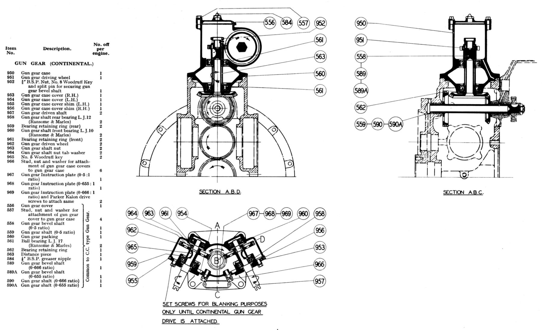
The gun gear was mounted at the top of the square shaped housing on the rear cover. A vertical cam drive was employed operating C.C. generators for firing two guns. Since the guns fired through the airscrew the final drive speed was varied to suit the reduction gearing used. Three bevel gear sets were available to suit the 0.5:1, 0.666:1, and 0.655:1 reduction gears. The gun operating gear and its drive could be removed as a whole and the rear cover blanked off if necessary.
The gun gear driving shaft was driven from the crankshaft through the magneto intermediate gear and was supported at the forward end in a magnesium bush in the rear cover and at the rear end in a bronze bush in the distributor drive casing. Driven by the integral bevel on the horizontal shaft was the vertical bevel shaft running in ball bearings housed in a light alloy conical casing. The lower bearing was located against a shoulder in the casing and was retained in position by a circlip; the upper bearing was freely positioned to find its own location in the casing. A distance piece separated the two bearings. Keyed to the shaft top end was a duralumin gun gear driving disc that was finely serrated on the top outer ring and had a lip extending downwards forming an oil thrower. Interposed between the top bearing and the driving disc was another brass oil retaining shim. Located on the driving disc boss were two fire control cams. These were serrated on both sides to fit the driving disc serrations, the cam lobes being formed on their outer periphery. These cams were suitable for two-bladed airscrews only. The shaft length was slightly less than the cam assembly, which was secured to it by a washer and a thin slotted nut; the open end of the split pin turning over into the hollow shaft end. Gear adjustment was provided by a laminated shim fitted between the gun gear case flange and the rear cover top.
Two Gun Gear Generator adaptors were attached by two-stud flanges to the gun cam case. A duralumin gun gear tappet guide was fitted to the adaptor bore and was retained by a flange on the inside, and by a nut on the outside. The reduced-diameter outer half had a special two-pipe union and nut at its extreme end. A hardened tappet, larger at its inner end and carrying a roller freely mounted on a pin operated in the guide. The smaller end of the tappet working in the guide sleeve was still further reduced to form an integral stud over which was fitted two cup leathers separated by a brass washer . These were retained on the tappet by a brass nut. Imprisoned in the tappet bore was a spring that pressed on a cap located against a hardened steel cotter. The cotter registered in two elongated slots in the tappet guide and was extended on each end to form an anchorage in the generator casing. The spring normally kept the tappet off the cam track when the guns were not in use. A longitudinal oil groove was machined down each side of the tappet to release any paraffin that might leak past the leather cup washers. Paraffin getting past the gland drained to the gun gear housing bottom and was carried away by an external pipe to atmosphere. The cam tracks were lubricated by grease admitted through a nipple in the top cover.
The gun gear driving shaft with its integral driving bevel rotated at engine speed. For the 0.5:1 reduction gear a shaft and bevel gear with 14 teeth was used. This meshed with the gear on the vertical shaft, which had 28 teeth, giving the gun cams a speed to equal to the airscrew or half engine speed. The 0.666:1 reduction gear used a driving shaft with an 18-tooth bevel gear that drove the 27-tooth vertical shaft gear, giving a speed reduction of 0.666:1, or airscrew speed. When the 0.655:1 gear was used a driving shaft with a 19-tooth bevel gear that drove the vertical shaft gear with 29 teeth giving a reduction of 0.655:1 from engine speed.
The Continental mechanically-operated gun gear drive could be fitted when required. This drive was similar to the English type but provided two rotating shafts for gun operation instead of a reciprocating motion. The vertical shaft and bearings were the same, but the gun gear housing was different; the top half incorporated two chambers that housed the gun gear shaft bearings and gears. Keyed to the vertical bevel shaft immediately above the top bearing was the gun gear driving wheel, which was retained on the shaft by a nut locked by a split pin, the open end of which was turned into the shaft hollow end. Two gears were driven by the vertical spiral gear, each of which was keyed to a shaft set at an angle of 26° to the engine center line. Each shaft was mounted on two ball bearings; the outer one was located against a shoulder on the shaft and was housed in the casing cover and was retained by a circlip, while the inner bearing was housed in the gun gear casing and was also retained by a circlip. Located against the outer bearing was a case hardened driven gear, which was retained on the shaft by a nut and tab washer. The shaft outer end was made to fit the standard continental drive. The casing cover was attached by three studs, and at the point where the gun gear shaft passed through it an oil retaining groove was incorporated. Since the two shafts revolved in opposite directions it was necessary that the oil grooves also ran in opposite directions, and in order that the covers were not assembled incorrectly a stud in one cover was set off center. The outer cover facing had a spigot facing and six 5 mm tapped holes conformed to continental requirements. Interposed between the cover and the casing was a laminated brass shim for gear adjustment.
The vertical drive shaft for the English drive rotated at airscrew speed. This drove the two spiral gears that had a 2:1 reduction giving a final speed to each gun gear shaft of 1/2 airscrew speed.
Exhaust Ring
 |
 |
 |
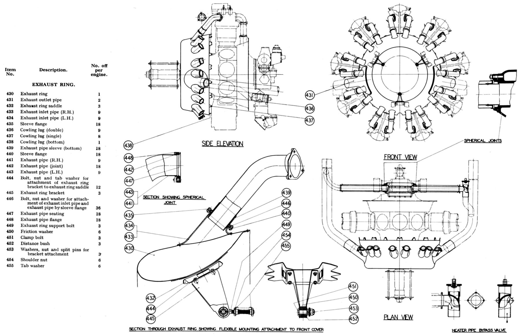 |
| Exhaust Ring, Support, Induction Heater | |||
The mild sheet steel Exhaust Ring was of was built up to form an annular chamber of streamline section. The ring was placed at the engine front and was supported at three points by brackets radiating from the front cover and that were equally spaced around it. Located in the three lugs were adjustable eye bolts to which the brackets were flexibly mounted. Ferodo discs were used to secure the ring brackets by frictional grip, the clearance holes being sufficiently large to allow for any expansion of the ring during running. The outer ends of the supports were bolted to saddles welded to the inside of the ring. Nine double lugs, eight single lugs, and one bottom single lug, welded to the ring trailing edge and extending rearward, provided a means for attaching cowling panels. Two large diameter tail pipes riveted to the ring outer face, and spaced one on each side of it, just below the engine center, accommodated extensions suitable to the various aircraft types. A local indentation in the ring rear edge between the two bottom cylinders was necessary to allow oil sump filter withdrawal.
Secured to the cylinder head exhaust ports by three studs were the were exhaust outlet pipes. Spherical seatings were used to form universal joints, each being pulled up to the cylinder head by a flange. The lower pipe end fitted into a sleeve that was bolted to stub pipes and riveted to the exhaust ring. In this way a flexible joint was provided allowing the pipe to expand freely as the ring became heated.
The Pegasus II-L had an exhaust-heated induction elbow. The heat for this came from the exhaust ring tail pipes when an exhaust ring was fitted, and direct from the cylinder exhaust ports where open exhaust or snouts were used; jacketed pipes combining spherical joints at their inner ends were provided where the exhaust gases passed through the cowling. The heater pipes and outer casing pipes were made up to suit each particular aircraft and were not supplied by the engine maker unless specially ordered. The end flanges and joints, however, were supplied. In some installations where difficulty was experienced in providing suitable clearance for the straight heater pipes these have been made with a slight set or bend. In certain other cases a special malleable iron finned elbow was used. A bypass valve could be provided to control the amount of exhaust gas to the heater elbow. When fitted this accessory was mounted on the inlet side.
Air Intake
 |
 |
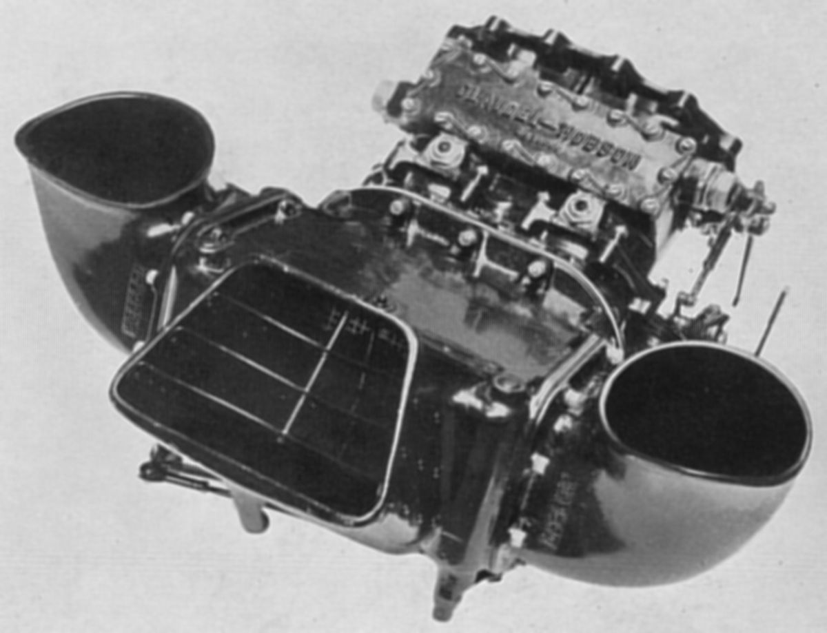
| Heated Air Intake | |
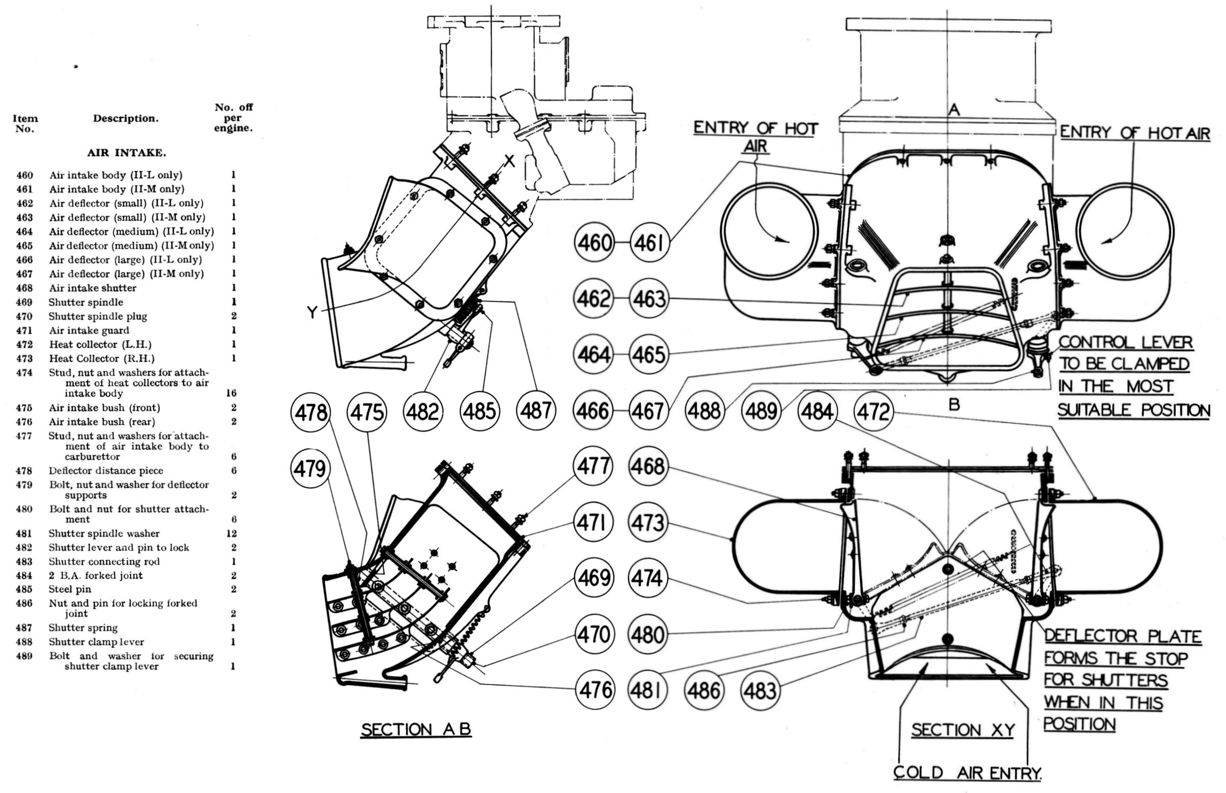
The heated Air Intake was of the variable hot and cold type, and was attached to the carburettor body underside by twelve studs, six of which were screwed into the carburettor, and six to the air intake flange. The main body was a cast aluminium alloy elbow that drew cold air from the engine front between cylinders 5 and 6. The exhaust-heated elbow on the II-L engine lowered the carburettor approximately 18" below that of the II-M engine. This necessitated different air intake castings for each type since the intake mouth was kept in the same position relative to the engine center line for both types. Two cast magnesium side pieces were bolted one on each side of the main body, and extended forward to the rear of cylinders 5 and 6, collecting hot air from the cylinders. Two shutters, controllable from the cockpit by Bowden or similar control, had a spring return and could be operated so that hot or cold air could be used as required. Air-straightening deflectors were riveted to the air intake body inside of the were provided as air straighteners, while the hot air the shutters themselves were formed to ensure a smooth air flow. This type of air intake was suitable for use with or without an engine cowl ring. When used without a ring the cold air was drawn through the intake main body, which extended sufficiently far forward to catch the air stream. When used with a cowl ring a tunnel inside the cowl was arranged so that the rear end lined up with the intake mouth, thus ensuring that cold air was brought from the front of the engine.
As a precaution against the entry of foreign matter, a coarse mesh gauze guard was interposed between the air intake face and the carburettor.
Inter-Cylinder Baffles
 |
 |
 |
| Inter-Cylinder Baffles: Front, Rear | ||
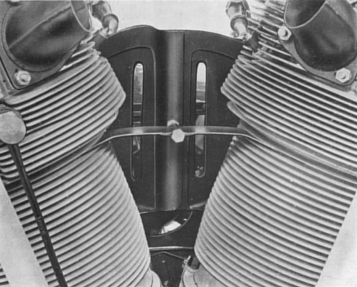
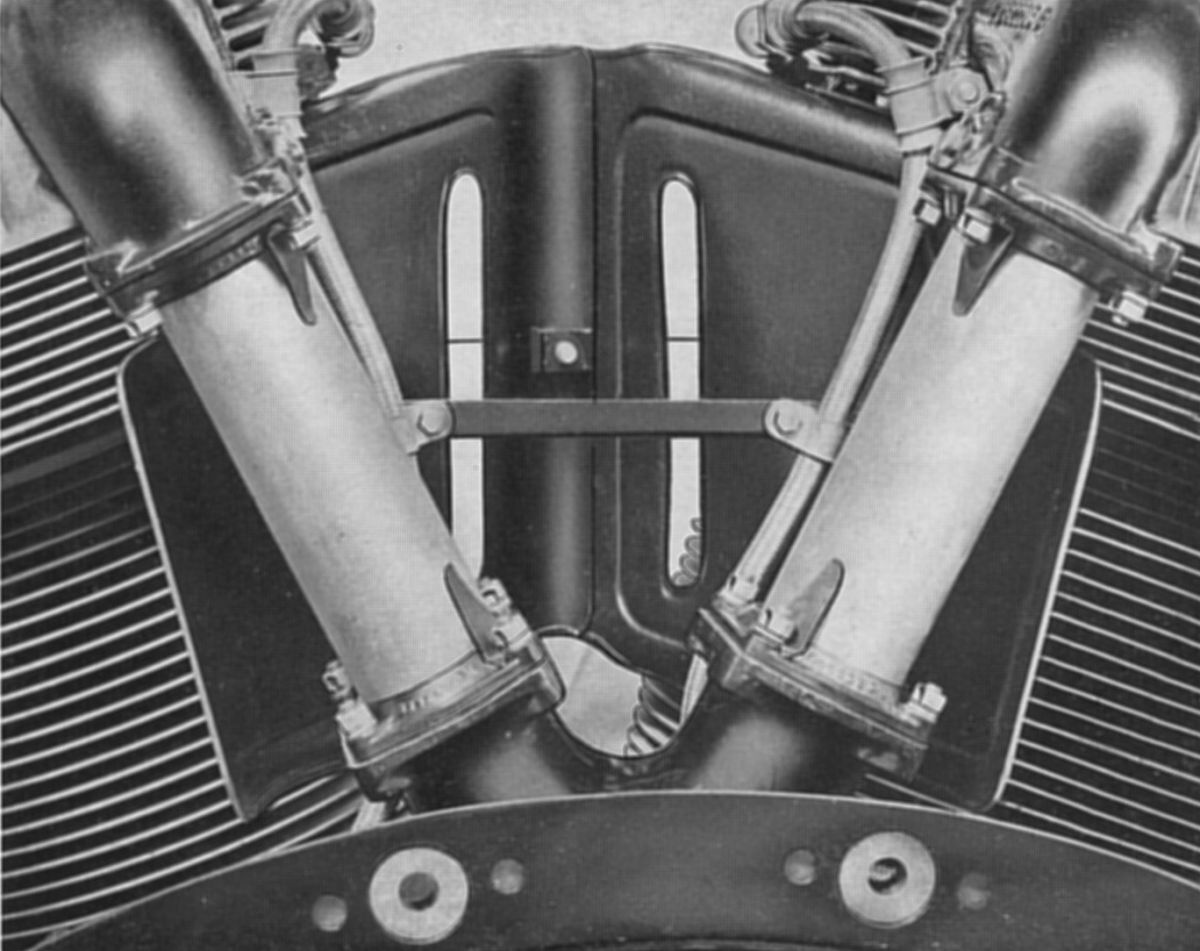
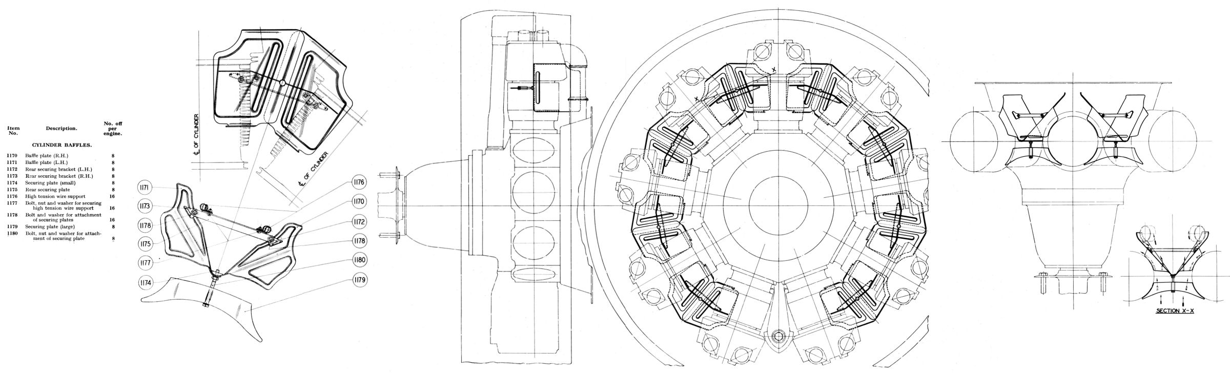
Inter-cylinder baffles were intended for use on installations with ring cowlings. Due to the reduced cooling air passing through the cylinders when this type of cowling was used, it was desirable that an air flow was deflected around the rear of the cylinders. The baffles were not recommended for use with standard cowlings, as the drag was unduly high; used in conjunction with certain ring cowling installations, however, the drag was reduced to negligible proportions and the cylinder cooling appreciably improved. (Compiler's Note: This is an example of old-school thinking about air-cooling, which took decades to properly understand. With the advent of the NACA cowling, the baffle penalty was eliminated and tight-fitting baffles became manditory for proper cooling and low drag.)
The sheet steel baffles, suitably ribbed and beaded, were produced in two halves. They were positioned between the cylinders extending forward to within approximately 3/4" of the cylinder center line. Rearward they opened out and extended to the inlet pipes, a 1/4" clearance being allowed between the pipes and the baffle plates. They were positioned vertically by flanges fitting between the cylinder fins. A single sheet steel securing plate locating also in the fins but forward of the cylinder center line retained the baffle plates in position by means of a clamp bolt attached to it. Two brackets that were riveted to the rear of the baffle plates) supported a sheet steel cross member, which carried the high tension wire supports.
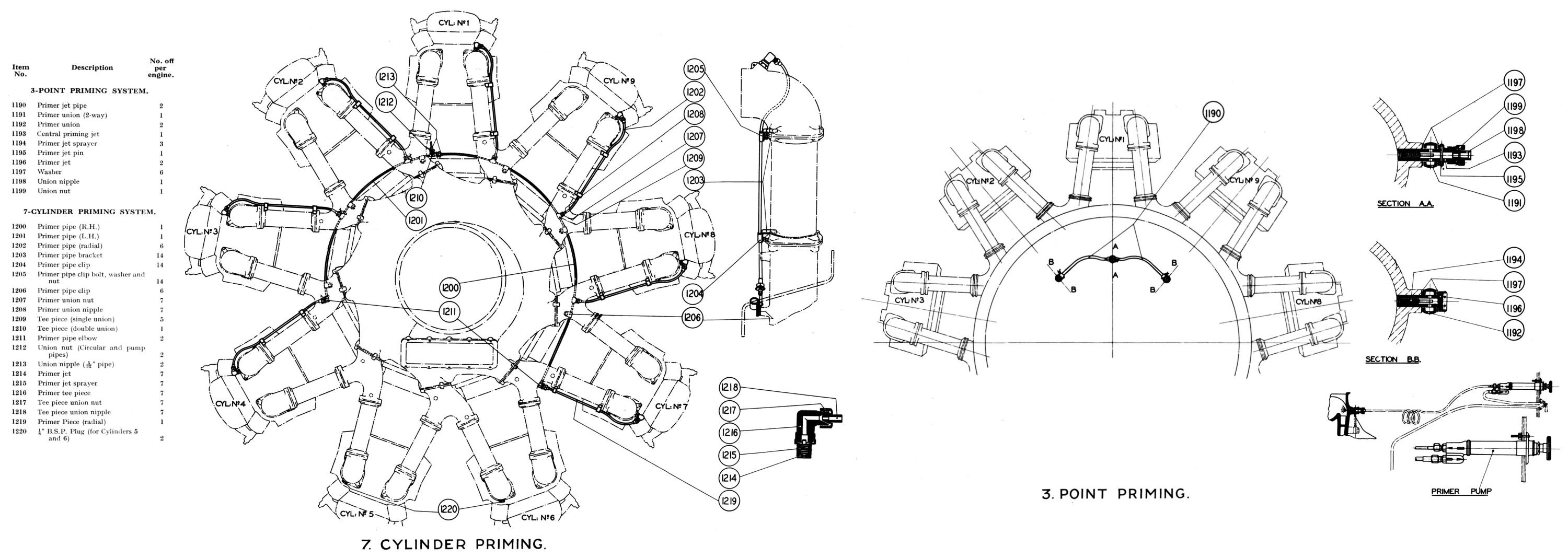
Priming System
 |
| Priming Systems |
To facilitate engine starting a priming system that sprayed fuel into the induction system was used. Two types were available: a Three Point Priming System that consisted of three sprayer nozzles screwed into the volute casing rear and connected by small-diameter copper pipe to a hand fuel pump; and the " Cold Climate (7-cylinder) Priming System, in which sprayer nozzles were screwed into the inlet pipe elbows of seven cylinders. Each cylinder was fed by a pipe radiating from a common supply pipe that surrounded the crankcase.
Three Point System. Screwed into three bosses on the volute casing were three steel priming jets. The two outer ones were hexagon headed, while the central one was extended beyond the hexagon to form a union connection for the feed pipe. The stems of the jets were hollow and were closed at the inner end except for a small orifice forming the jet. The side jet outer ends were also plugged, the end of the central one, however, was left open to receive the charge. Inserted in the jet stem was a brass sprayer, a loose piece embodying a two start thread which served to atomize the fuel. A small diameter pin inserted through the central nozzle hexagon prevented the sprayer from working out.
Fuel was delivered through a pipe line from a hand pump to the central jet where it passed through two holes in the stem to a two-way banjo, which in turn was connected by steel pipes to the banjos feeding the side nozzles.
Cold Climate Priming System. Fuel from the hand pump was delivered to a circular supply pipe through a two-way connection. The supply pipe, which was made in two halves, was attached by clips to the lower high tension wire attachment bosses of cylinder Nos. 1, 2, 3, 7, 8 and 9 inlet pipe branches. Five branch pieces were fitted at regular intervals around the supply pipe, which in turn were connected by nuts and nipples to the individual radial priming pipes. The supply pipe ends were terminated by right angle elbows to which were attached the radial pipes supplying cylinders 4 and 7. The radial priming pipes were carried up the sides of the inlet pipes and were steadied by sheet metal clips attached to angle brackets that were secured to the inlet pipe branch flanges and the inlet pipe elbows. Each pipe terminated in a nipple and nut and was attached to an elbow that was screwed into a steel jet. The jet itself was screwed into a boss on the inlet pipe elbow, and was secured by a locknut. Imprisoned in the jet was a short brass sprayer, which served to atomize the fuel.
Special Installation Features: Oil and Fuel Systems
 |
 |
| Oil System Filters and Heater | |
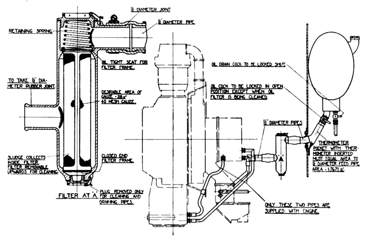
Oil System. Bristol intended the oil tank to be located so that its sump base above the engine center line when the aircraft was in the tail down position; the positive head was for all practical purposes unlimited, as a spring-loaded check valve was incorporated in the oil pump. The oil tank capacity was to be based upon the fuel tank capacity allowing for the maximum possible flight duration, with a further 2 gallon allowance on the total oil for circulation purposes in addition to the usual 1 gallon air space allowance.
All oil circulation pipes were 3/4" diameter, except the feed pipe from tank, which was 1.5" diameter to ensure free oil flow to the engine for rapid throttle response under cold conditions. Where an auxiliary oil cooler was used, the Air Ministry required for the return pipe from the cooler outlet to be 1.0" diameter. If a shut off cock was fitted in the feed pipe it was to be of at least the same bore as the feed pipe, and as a safeguard against accidental engine running with the oil turned off, it was to have been positively locked in the open position. Due to the shortness and comparative rigidity of oil piping, flexible connections between the engine and the bulkhead were essential in order to relieve the engine and oil tank connections of any vibrational movements tending to unscrew them, or cause fatigue fracture in the tank or pipes. Rubber connections were suitable, provided they were wrapped with metallic gauze, wire, or asbestos, to comply with Air Ministry requirements. Bristol advised that a main oil filter of 40 mesh gauze and approximately 28 in² area be included in the feed system as the engine feed filter was of coarse mesh owing to its comparatively small area. The main filter was to have been of the type in which foreign matter was retained inside the gauze, which could be lifted out leaving its container still full of oil, thereby preventing air entrapment in the filter and pipeline upon reassembly after servicing. When the bottom drain plug was removed to facilitate washing the filter body inside, the air could be expelled from the filter on reassembly by turning on the oil cock and allowing the body to fill with oil before the cover was replaced. Any filter type that necessitated the removal of its base for service, and which could seals an air column inside the main engine oil supply, was not recommended.
Oil Tank Partial Circulating Device. Air-cooled engines rapidly reached their working temperatures, even when starting at extremely low air temperatures. However, the need to warm up the oil system always delayed full-power operation. A simple device was fitted to most installations for rapidly heating feed oil. The heated engine return oil passed into a small-capacity perforated chamber located in the main oil tank. The feed outlet from the tank to the engine came from the lower part of this chamber, and when starting with cold oil, the warm return oil from the engine was quickly brought back into circulation. The main body of cold oil was warmed by the hot oil in the chamber and flowed into the chamber as required, through the perforations at the bottom. A means was to be provided to remove this partial-circulating device from action during hot weather; this was accomplished by transferring the warmed return oil to either the partial circulating chamber or to the main tank body. This change from summer to winter conditions was to be made when the average starting air temperature was approximately 10°C.
Fuel Pump and Relief Valve. The carburettor was tested to function correctly at fuel heads between 10" and 144". These figures corresponded to approximately 0.4 psi and 4.0 psi. A pressure of 2.0 psi at the carburettor was considered ideal and was also the value to which the fuel pump relief valve was set. Some fuel systems may have included a circuit in which the pump also had to raise fuel to a gravity tank placed at a considerable height above the carburettor. The pressure taken to feed this tank and the carburettor at the same time may result in a higher pressure on the carburettor than the desired 2 psi, and in this case, 3 psi was taken as the maximum. The relief valve on the fuel pump was housed internally in the fuel pump body, and adjustment was made by releasing a lock nut and screwing the adjustment screw in or out. Springs of varying strengths were supplied to suit varying installations. The relieved fuel passed from the pressure side to the suction side of the pump. In any fuel system where the pump was called upon to raise fuel to a considerable height, and at the same time draw the supply from a gravity tank below it, a spring of sufficient strength was selected to withstand the effect of the suction on the rear side of the relief valve.
Ignition Wiring. During aircraft inspection prior to installing a new engine, the ignition wiring and switches were to be tested. Where the hand starting magneto was located some distance from the engine, the high-tension wire insulation was also to be tested.
Send mail to
![]() with questions or comments about this web site.
with questions or comments about this web site.
![]()