Cutaway
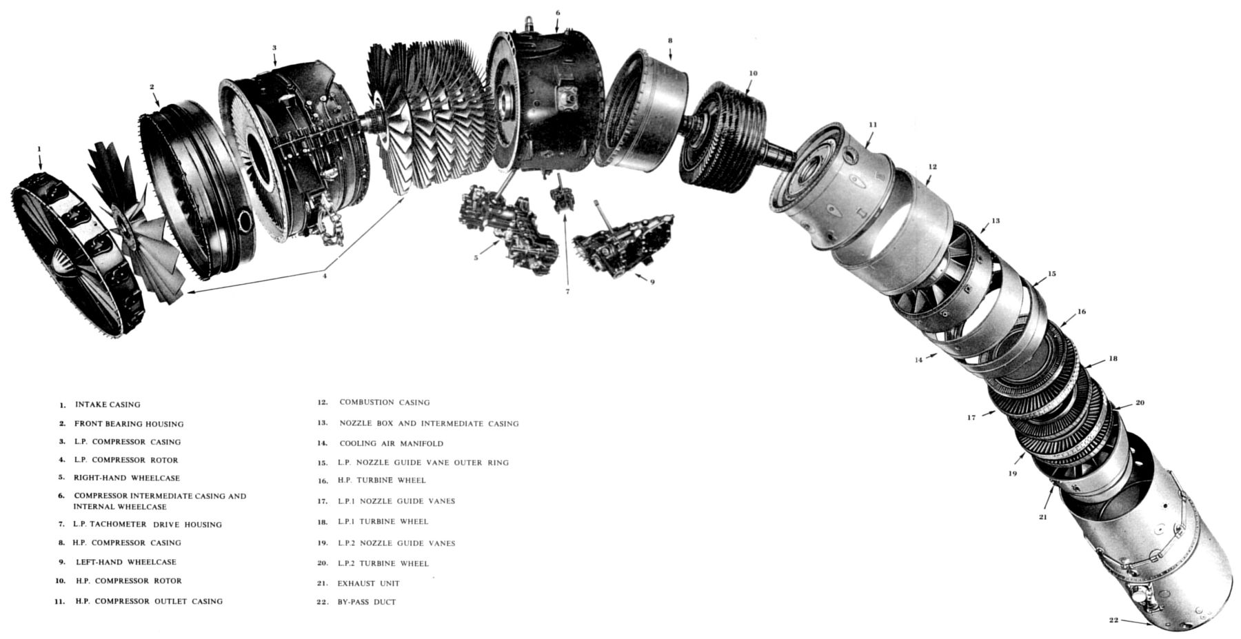
Exploded View
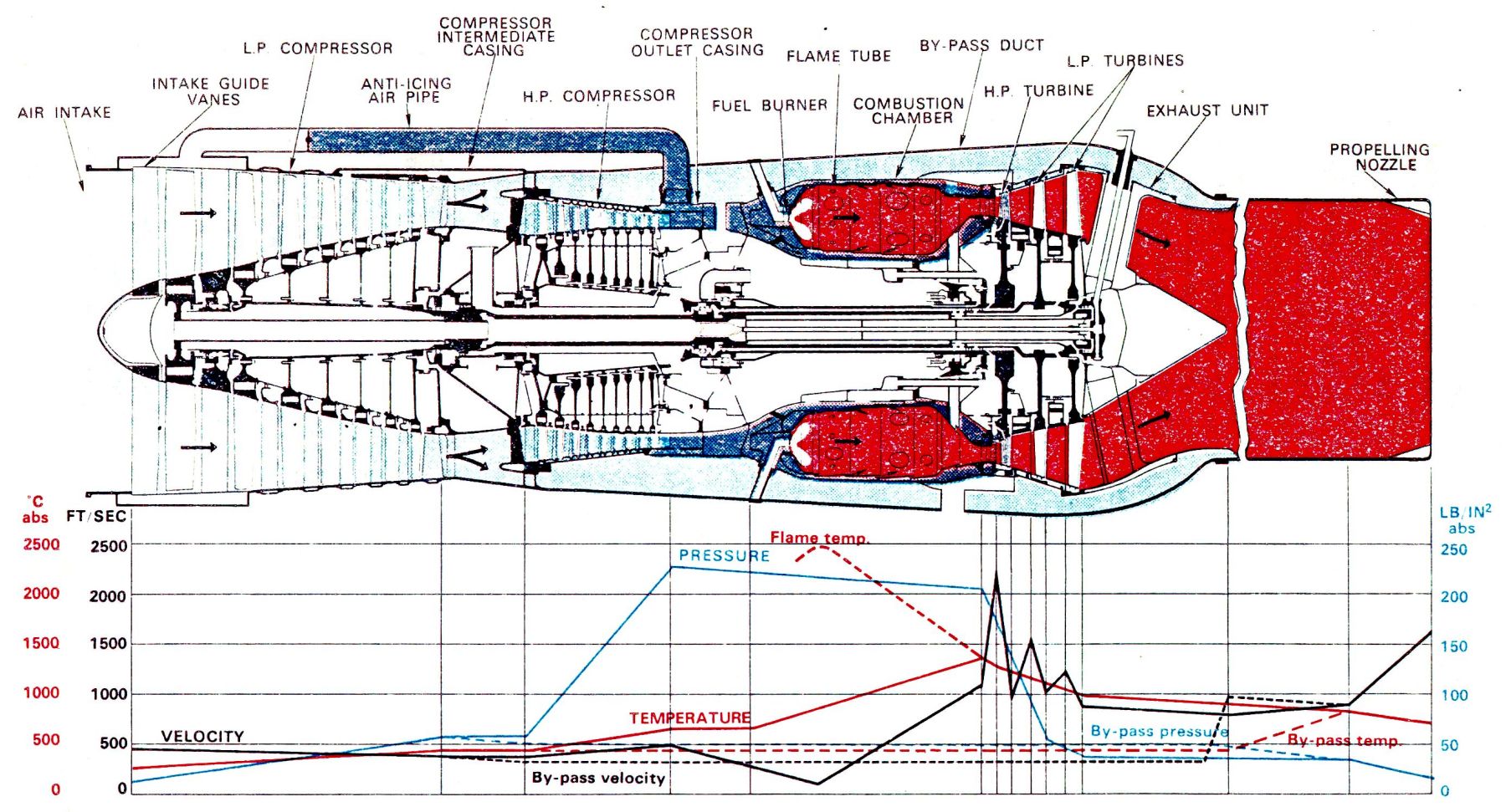
Gas Flow Diagram
Rolls-Royce Conway
Construction Details
|
|
|
Cutaway |
Exploded View |
Gas Flow Diagram |
Cutaway Legend
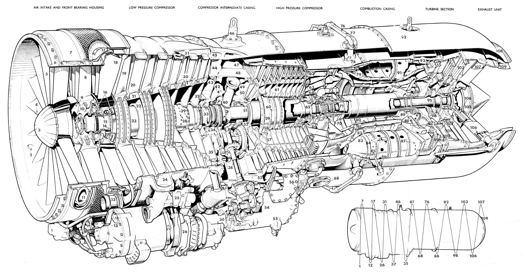
Air Intake And Front Bearing Housing |
||
| 1. Fuel filter differential pressure switch | 2. Ram pressure tapping for fuel control unit | |
| 3. Nose fairing (anti-iced) | 4. Ram pressure tapping for altitude sensing unit | |
| 5. Intake guide vanes (anti-iced) | 6. Air intake extension ring | |
| 7. Anti-icing air manifold (surrounding air intake casing and front bearing housing) | 8. Stage 0 low pressure (LP) rotor blades | |
| 9. Rotor blade retaining pin | 10. Stage 0 rotor retaining flange | |
| 11. Inlet guide vane anti-icing air outlet | 12. Oil-cooled AC generator | |
| 13. Front bearing housing rear manifold air outlet | 14. LP compressor shaft front section | |
| 15. LP compressor front bearing | 16. Front and rear air seals | |
| 17. Anti-icing air supply pipe | 18. Stage 0 stators | |
Low Pressure Compressor |
||
| 19. Stage 1 compressor blades | 20. Stage 1 stators | |
| 21. Interstage spacer ring | 22. Interstage seal | |
| 23. LP compressor shaft | 24. Stage I cooling air supply | |
| 25. Cooling air valve actuator | 26. Constant speed drive unit | |
| 27. High pressure (HP) air supply to fuel heater | 28. Front bearing sealing air transfer holes | |
| 29. Rotor wheel driving splines | 30. LP sealing air bleed holes | |
| 31. Stage 3 cooling air bleed | 32. Air sealCompressor Intermediate Casing | |
| 33. Rotor assembly retaining nut | 34. LP compressor rear bearing | |
| 35. Oil feed to accessory drive shaft bearing | 36. CSD gear train | |
| 37. Wheelcase oil jet | 38. Left wheelcase driving gear | |
| 39. LP tachometer driving gear | 40. LP cooling air transfer tube | |
| 41. Bearing oil jet and transfer tube | 42. LP cooling air manifold | |
| 43. Internal wheelcase front panel | 44. LP compressor outlet guide vanes | |
| 45. Engine cooling air inlet | 46. Engine locating pillar and front slinging eye | |
| 47. By-pass duct entry | 48. HP compressor intake guide vanes | |
| 49. Internal wheelcase rear panel | 50. Air seal | |
| 51. HP compressor front bearing | 52. Accessory driving gear on h.p. compressor shaft | |
| 53. Centrifugal breather drive | 54. Left wheelcase and sump | |
| 55. Sump pressure filling connection | 56. Sump oil level sight glass | |
High Pressure Compressor |
||
| 57. HP compressor shaft (front section) | 58. Cooling air flow divider tube | |
| 59. HP compressor shaft (rear section) | 60. HP cooling air transfer holes | |
| 61. HP cooling air bleed holes | 62. HP compressor outlet guide vanes | |
Compressor Outlet Casing |
||
| 63. HP cooling air transfer manifold | 64. Air seals | |
| 65. LP rotating assembly thrust bearing | 66. LP cooling air transfer holes | |
| 67. Oil supply to turbine and thrust bearings | 68. HP air supply to aircraft services | |
| 69. HP air tapping collector air manifold | 70. HP rotating assembly thrust bearing | |
| 71. LP turbine shaft | 72. HP turbine shaft | |
| 73. Air pressure balance pipe | 74. HP cooling air outlet to by-pass duct | |
| 75. Thrust bearing housing vent | 76. Main burner manifold | |
| 77. Primary burner manifold | ||
Combustion Casing |
||
| 78. Flame tube snout | 79. Burner head | |
| 80. HP turbine bearing oil return pipe | 81. Intermediate casing - compressor outlet casing to nozzle box | |
| 82. Combustion chamber inner casing | 83. HP turbine casing cooling air transfer holes | |
| 84. Interconnector | 85. Flame tube | |
| 86. High-energy igniter plug | 87. Flame tube bulkhead panel | |
| 88 LP cooling air outlet duct | 89. HP turbine bearing | |
| 90. Turbine cooling air transfer manifold | 91. Discharge nozzle | |
Turbine Section |
||
| 92. Rear suspension link and slinging eye | 93. LP cooling air outlet manifold | |
| 94. LP turbine rear bearing | 95. Turbine cooling air transfer tube | |
| 96. Turbine cooling air transfer holes | 97. LP turbine interstage seal | |
| 98. HP nozzle guide vanes (air cooled) | 99. HP turbine blades (air cooled) | |
| 100. LP1 nozzle guide vanes | 101. LP1 turbine blades | |
| 112. LP2 nozzle guide vanes | 103. LP2 turbine blades | |
| 104. LP turbine rear bearing and thrust bearings oil feed | ||
Exhaust Unit |
||
| 105. Inner cone | 106. By-pass cooling air feed | |
| 107. Exhaust cone support strut | 108. Jet pipe attachment ring | |
| 109. Outer cone | ||
Internal Details
 |
 |
 |
 |
 |
 |
 |
 |
 |
 |
 |
 |
 |
 |
 |
Photo album created with Web Album Generator