Boeing Gas Turbines
Compiled by Kimble D. McCutcheon and Doug Culy
Published 31 Oct 2023; Revised 6 Nov 2023
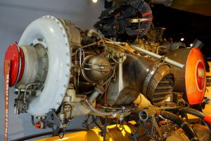
Boeing T50-BO-12 in Gyrodyne QH-50D (Wiki) |
When the turbojet was finally revealed in 1943, U.S. Army Air Forces became interested in powering large aircraft with them. Boeing realized that if large jet-powered military aircraft proved successful, the airlines would want them, so Boeing began planning large jet-propelled aircraft. In order to understand these new engines, Boeing questioned several gas turbine manufacturers, but got conflicting accounts of the new technology; thrust, life, operating temperatures and fuel economy estimates varied wildly. To gain better data, Boeing started its own jet propulsion research in June 1943. |
Introduction
Boeing built and tested various gas turbine components in a purpose-built area at Boeing's Seattle, Washington Plant. There, engineering spaces, machine shops, assembly facilities and component test cells were constructed. Small axial- and centrifugal-flow compressors were built and tested, and finally the assembly and testing of complete experimental power units resulted in the construction of two small gas turbines. The Model 500 turbojet was assembled in 1947, and the Model 502 turboprop was assembled in 1949.
While this work started as a research endeavor to explore the characteristics of gas turbine engines, Boeing realized that these engines might produce an income stream. Development of the two engines proceeded through the late-1940s. The first engine to run was the Model 500, and the Model 502 quickly followed. Boeing announced these two engines in 1947. The Model 500 turbojet was considered suitable as a large jet engines starter and also for missile, glide bomb, and small aircraft propulsion. The Model 502 turboprop was offered for use in light aircraft, although it was anticipated that early use would be as an auxiliary power unit in large aircraft and as a ground power unit. These engines benefited from the close cooperation among Boeing's several engineering groups, including acoustics, vibration, electronics, process, and metallurgy, each with its own laboratory and specialists. These groups, together with Boeing's jet propulsion laboratory, resulted in a research organization considered by Boeing to be unparalleled at that time by any other U.S. aircraft gas turbine concern.
Development
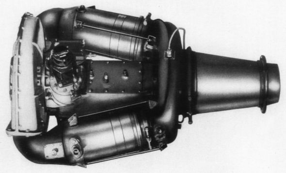
The Model 500 was a single-shaft turbojet with a single-entry centrifugal compressor, two can-type combustors, and a single-stage axial turbine. The Model 500, first run in 1947, was rated at 150 lbt, had a 1.3 lb/hp/hr sfc, and weighed 85 lb. By 1954, the thrust was 195 lb, and engine weight was 120 lb. Compressor and turbine modifications achieved the performance increases. Boeing continued developing and marketing this engine, but it found no applications. Boeing's small engine work then became focused on free-turbine turboprops and turboshaft engines, derived from the Model 500.
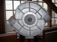
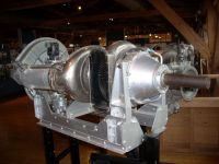
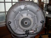
The Model 502 was initially a turboprop and later a turboshaft engine. The 502 used a 500 power section, but a single-stage free power turbine and gearbox were added. First run in 1947, the 502 weighed 140 lb and produced 120 shp with a 1.8 lb/hp/hr sfc. In 1949, Boeing delivered six engines to the Navythat produced 160 shp with a 1.5 lb/hp/hr sfc. The refined engine had an aerodynamic upgrade, thickened turbine blades, compressor structural changes, a new accessory section/gearbox, and a more reliable fuel control system.
The Model 502-10C turboshaft increased output from 120 to 240 shp with a 1.02 lb/hp/hr sfc, but weight also increased to 320 lb. Production cost and time between overhauls was on par with reciprocating engines. By 1965, the Model 502-10VC turboshaft was producing 300 shp at a 0.98 lb/hp/hr sfc.
 |
 |
 |
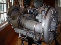 |
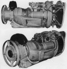
| Boeing 502-1-1 | Boeing 502-10 |
| Images Courtesy of Tom Fey, taken at the Seattle Museum of Flight |
t.jpg) |
t.jpg) |
t.jpg) |
t.jpg) |
t.jpg) |
t.jpg) |
| Boeing 502-BO-10VC (T50-BO-8A) Turboshaft (NASM) |
Marine Power
| Boeing Model 540 Cycle Parameters |
| Turbine Inlet Temperature | 1,550°F |
| Airflow | 1.615 lb/sec |
| Overall Pressure Ratio | 4.15 |
| Compressor Efficiency | 0.74% |
| Gas Generator Turbine Efficiency (T-T) | 85% |
| Power Turbine Efficiency (T-S) | 80% |
| Gas Generator Speed | 54,600 rpm |
| Power Turbine Speed | 34,500 rpm |
| |
| Boeing Model 540 Weight Breakdown |
| Gas Producer Section | 60 lb |
| Output Section | 40 lb |
| Propeller Drive Assembly | 35 lb |
| Transom Mounting Bracket | 30 lb |
| Starter and Alternator | 27 lb |
| Remaining Accessories | 10 lb |
| Shroud | 8 lb |
(T-T) = Through-turbine efficiency measurement.
(T-S) = Measurement involves stopping a small flow portion. |
In 1947, while the U.S. Navy Bureau of Ships was looking for a naval vessel power plant; the Model 502 acquired the T50 military designation. Boeing received the first Model 502 production contract during 1950 for engines to be used in Navy minesweepers using two 502-6 engines that drove an electric generator through a combining gearbox. The turboshaft 502 also served in air-start carts, fire truck water pumps, truck and traction power.
The Model 540. In mid 1959, Boeing prepared layout designs of several alternative outboard gas turbine engines for marine use, with the U.S. Navy’s needs particularly in mind. In mid 1960, a go-ahead was made to build a demonstrator, making use of some existing test-rig components that had been designed to evaluate improved small-engine technologies. The goal was a 100-shp free turbine outboard engine delivering 1.0 lb/hp/hr sfc, using commercial off-the-shelf components as much as possible. The demonstrator was mounted on a Mercury Model 800 outboard propeller drive unit. The demonstrator was running in a 20-ft boat by the fall of 1961, and a proposal to the Navy was made in March 1962.
The engine featured a monorotor gas generator (centrifugal compressor and radial-inflow turbine) and an axial power turbine. In the demonstrator, a radial turbine was used for the power turbine, and all rotors were hogged out of forgings; but they were to be cast in the production engine. Most of the controls and accessories were off-the-shelf items. A single reverse-flow thumb-type (stickeing out radially) combustor was used. A single-stage offset layshaft gear set provided 5.82:1 reduction. Early in its testing, the engine delivered its output goals
Boeing expected to easily grow the engine to 150 shp with 0.88 lb/shp/hr sfc at 1,775°F turbine inlet temperature. Production engine weight was estimated to be 180 lb, development engines were expected to weigh 210 lb, and the demonstrator weighed a few pounds more than that.
The Navy wanted a commercially available engine, and Boeing had discussions with a prominent outboard engine manufacturer, which expressed interest. However, Boeing would not commit to marketing a commercial engine, and the Navy did not accept the proposal. The Boeing engineers on the program were extremely disappointed; the demonstrator was shelved in 1962. So ended the Model 540, a beautiful and simple engine that would have revolutionized the boat engine market. Boeing had done its homework, and was envisioning using the 540 basic engine for auxiliary power unit, pumping, generating, etc., but there was no follow-through.
Aircraft Power Firsts
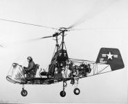
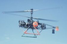
On 10 Dec 1951, a Model 502-2E (YT50) replaced the standard Lycoming O-435-A2 piston engine in a Kaman K-225, becoming the first gas turbine to power a helicopter. In 1952, the Navy became interested in pilotless helicopters for Anti-Submarine Warfare surveillance. Kaman did the initial experimentation and the Navy initiated a competitive procurement; on 6 Apr 1961, Gyrodyne of Long Island, New York, won with its proposal for the DSN-3, powered by a Model 502 (T50-BO-4) turboshaft producing 270 shp. Later, the DSN-3 was fitted with a 300 shp Model 502-10VC (T50-BO-8A) and was redesignated the QH-50C. The Model 502-10VC was the first U.S. 200 - 350-shp class to pass a 150-hour type test.
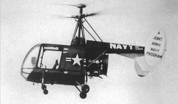
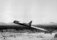
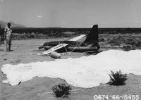
In November 1952, Boeing, Cessna, Army and Air Force installed a 210 hp Model 502-8 (XT50-BO-1) turboprop in a Cessna XL-19B; this was the first turboprop-powered light airplane. On 16 July 1953, the XL-19B set a light plane altitude world record of 37,063 feet. In 1960, the 300 shp Model 502-10F turboprop powered the Army's rocket-launched Radioplane RP-77D, a radio-controlled aerial gunnery target. On 24 Mar 1954, a Kaman HTK-2 equipped with two 502-2 engines became the first twin-turbine helicopter to fly. When Model 502 production ceased in 1965, about 1,500 turboshaft, turboprop, and ground power unit engines had been built.
Boeing Gas Turbine Firsts
 |
 |
 |
t.jpg) |
t.jpg) |
| Kaman K-225 (SDASM) |
Kaman HTK-1 Pilotless |
Gyrodyne QH-50D |
Kaman HTK-2 Twin Turbine |
Radioplane RP-77D Target Drone
t.jpg) |
t.jpg) |
 |
 |
 |
| Preparation |
Launch |
Recovery |
Model 502-10U Engine |
| From the Gerald Balzer Collection, Courtesy of the Greater St. Louis Air & Space Museum
|
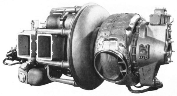
In early 1954, Model 520 series engine design began as a joint Navy/Boeing project. The initial helicopter version was the 430 hp Model 520-2 (T60-BO-2). This engine's gas generator had a double-entry centrifugal compressor, two reverse-flow combustion chambers, a single radial inflow turbine, and a single axial free turbine driving the power takeoff. The new double-entry compressor provided an airflow and pressure ratio increase of about 25% over the Model 502.
Three turboshaft and two turboprop Model 520 versions were rated from 430 to 550 shp with sfcs from 0.72 to 0.65 lb/hp/hr. By 1960, the Model 520-2 had passed its 50-hour Preliminary Flight Rating Test (PFRT), but the Navy's projected applications never happened and the 520 Series was never produced.
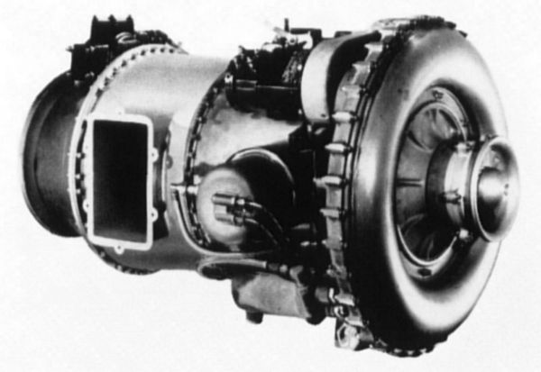
The 365 shp Model 550 (T50), introduced in the early 1960s, descended from the Model 502. Initially an improved and lighter Model 502 the 550 featured a single axial stage ahead of the single-sided centrifugal compressor stage, two new reverse-flow can-type combustors, and a radial inflow turbine driving the compressor. The Model 550's rated power increased by 65 shp and its weight decreased by 84 lb compared to the earlier Model 502-10VC; sfc also decreased from 0.98 to 0.80 lb/hp/hr. The Model 550-1 (T50-BO-12) entered production in the mid-1960s and powered the Gyrodyne QH-50D drone. Model 550 production continued until April 1968.
Despite its successes, by 1965 Boeing's Turbine Division had lost money for 17 straight years. Boeing was unwilling to commit the resources necessary to save the Division, plus, it needed capital and engineering resources for its new Model 747 airplane project. On 25 Jan 1966, Boeing announced plans to phase out its gas turbine engine operations over several years. Production commitments were to be met and a commitment made to support the 1,200 engines in service. On 7 Dec 1966, the Caterpillar Tractor Co. took over development and support. Boeing completed the last Model 550-1 (T50-BO-12) in April 1968. On 1 Mar 1969, Steward-Davis, Inc., a major turbine overhaul and repair facility located in Long Beach, California, took over development, manufacture, sales and service of Model 502 and T50-BO-10/12 engines.
Boeing Gas Turbine Data
Boeing Model 500
 |
|---|
| Type | Turbojet, centrifugal flow compressor, multiple combustion chambers, single-stage turbine. |
| Compressor | 1-stage centrifugal flow compressor. 2-piece aluminum alloy casing integral with diffuser. 2 tangential outlets and vaned elbows connecting with combustion chambers. 2-piece aluminum alloy impeller unit comprising an inducer section with 22 blades attached to front of main impeller having 22 blades. Compression ratio 3.0:1. Air mass flow 3.25 lb (1.5 kg)/sec @ 36,000 rpm, sea level static. |
| Combustor |
2 independent tubular stainless steel combustion chambers, straight-through flow type. 1 perforated stainless steel flame tube inside each combustion chamber. 1 fuel injector nozzle projecting into center of front portion of each flame tube with downstream injection. |
| Turbine | 1-stage axial flow gas turbine. Fabricated steel diaphragm with 27 inserted nozzle guide vanes. Rotor disc of special alloy steel with 64 welded solid blades. Turbine rotor mounted on same shaft as compressor impeller with shaft supported in 2 anti-friction bearings. Gas temperature 1,500°F (815°C) before turbine and 1,250°F (677°C) after turbine @ 36,000 rpm |
| Exhaust nozzle | Stainless steel outer casing and fixed inner cone. |
| Fuel system | Single fuel manifold system. 1 Boeing fuel pump and governor, maximum pressure 400 psi (28 kg/cm²). |
| Lubrication | Wet sump system with pressure feed to main bearings. Gear-type pump, pressure 50 psi (3.5 kg/cm²). High-pressure filter. |
| Starter | Compressed air starter, pressure 90 psi (6.3 kg/cm²). 2 igniter plugs and 2 ignition coils. |
| Diameter. length | 22.0" (559 mm), 29.0" (737 mm) |
| Frontal area | 2.2 ft² (0.20 m²) |
| Weight | 85 lb (38 kg) |
| Weight/thrust (static) | 0.57 lb/lbt (0.57 kg/kgt) |
| Fuel grade | AN-F-34, JP-2, kerosene |
| Oil viscosity (at 100°F) | 59 S.U. (AN-0-9 1010) (10.0 cs viscosity (at 38°C)) |
| Fuel consumption (cruise) | 1.30 lb/lbt/hr (1.30 kg/kgt/hr) |
| Oil consumption (cruise) | 0.5 lb/hr (0.2 kg/hr) |
| Rating (take-off, static) | 150 lbt (70 kgt) @ 36,000 rpm, sea level |
| Rating (normal, static) | 150 lbt (70 kgt) @ 36,000 rpm, sea level |
| Rating (cruising, static) | 110 lbt (50 kgt) @ 32,000 rpm, sea level |
| This turbojet can be used for small airplanes, guided missiles, starting large turbojets or turboprops, or for other auxiliary purposes. |
|
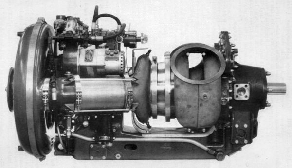
Boeing Model 502-10B (T50)
 |
|---|
| Type | Turboprop, 1-stage centrifugal compressor, 2 combustion chambers, 2-stage turbine, 1 drive shaft. |
| Compressor | 1-stage centrifugal type. Front air intake with large diameter silencer. 2-piece aluminum alloy casing with integral diffuser and 2 axial outlets. 2-piece aluminum alloy impeller unit comprising inducer section with 19 vanes attached to front of main impeller with 19 vanes, mounted on compressor-turbine rotor shaft supported in 2 ball bearings. Pressure ratio 4.25:1, and air mass flow 4.0 lb (1.8 kg)/sec @ 36,000 rpm, sea level, static. |
| Combustor | 2 tubular stainless steel combustion chambers, of straight-through flow type, attached to aluminum alloy adapters clamped to compressor casing outlets. 1 perforated flame tube inside each combustion chamber. 1 fuel burner in each adapter with downstream injection. |
| Turbine | 2-stage axial flow type. Fabricated steel diaphragm with 31 inserted solid nozzle vanes. 2 independent turbine wheels with 1st-stage wheel mounted on compressor rotor shaft, driving compressor; and 2nd-stage wheel with integral stub shaft supported in 3 plain bearings, connected to reduction gear. 1st-stage rotor has 66 welded-on blades and runs at 36,000 rpm, and 2nd-stage rotor has 50 welded-on blades and runs at 26,000 rpm, at normal engine speed. Rotor discs of Timken 16-25-6 alloy. Gas temperature 1,550°F (843°C) before 1st-stage turbine, and 1,075°F (579°C) after 2nd-stage turbine, at 36,000 compressor rpm |
| Exhaust | Fixed area type. Annular manifold with bifurcated outlets. |
| Drive shaft | Single output shaft driven through double planetary reduction gears, ratio 0.112:1 (8.90:1), by 2nd-stage free turbine rotor. Drive shaft supported in 1 ball thrust bearing and 1 plain bearing. |
| Control system | Woodward hydro-mechanical type with manual starting and acceleration controls. Single lever master control. |
| Fuel system | Single fuel manifold system. 1 Pesco 022816 gear type pump, 600 psi (42 kg/cm²) with centrifugal governor and acceleration limiter. |
| Lubrication system | Return type. Lear-Romec vane-type pump with 1 pressure unit, 150 psi (10.5 kg/cm²), and 1 scavenge unit. Filter. |
| Accessories | Electric starter-generator. Bendix-Scintilla capacitor discharge ignition system with 1 high-energy ignition unit and 2 vaporizing type igniter plugs. |
| Width, height | 22.7" (577 mm), 22.7" (577 mm) |
| Length (as shown) | 42.8" (1,087 mm) |
| Frontal area | 3.4 ft² (0.31 m²) |
| Weight (without propeller) | 245 lb (111 kg) |
| Weight/maximum shp | 0.91 lb/shp (0,41 kg/shp) |
| Fuel specification | MIL-F-5572A, MIL-F-5624B, JP-4, gasoline, kerosene |
| Oil specification | MIL-O-2104 (SAE 10) (11.6 cs viscosity at 100°C) |
| Fuel consumption (normal) | 1.02 lb/shp/hr (0.46 kg/shp/hr) |
| Oil consumption (normal) | 0.10 lb/hr (0.04 kg/hr) |
| Take-off, static | 270 shp @ 37,000 turbine rpm, 3,090 propeller rpm |
| Max. cont., static | 240 shp @ 36,000 turbine rpm, 2,920 propeller rpm |
| 502-2F (YT50-BO-2) Similar to 502-10B. Pressure ratio 3.15:1. Air mass flow 3.6 lb (1.6 kg)/sec. Weight 230 lb (104 kg). 175 shp @ 36,000 turbine rpm, take-off. |
| 502-6, -8B: Similar to 502-10B. Pressure ratio 3.0:1. Weight 267 lb (121 kg). 210 shp @ 37,500 turbine rpm, take-off. |
|
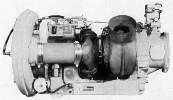
Boeing Model 502-10C
 |
|---|
| Type | Turboshaft with gas producer section comprising 1-stage centrifugal compressor, 2 combustion chambers and 1stage turbine; and power output section comprising 1-stage free turbine and reduction gearbox with shaft power outlet. |
| Compressor | 1-stage centrifugal flow type. 2-piece aluminum alloy casing. 2-piece single-entry aluminum alloy impeller with 19 vanes, mounted on front of drive shaft supported in 2 slipper bearings. Pressure ratio 4.25:1, and air mass flow 4.0 lb (1.8 kg)/sec |
| Combustor | 2 interconnected tubular combustion chambers. 1 fuel burner in each flame tube with downstream injection. |
| Turbine (gas producer) | 1-stage axial flow type. Steel casing with 31 solid nozzle vanes. Turbine wheel of Timken 16-25-6 alloy with 66 welded-on blades, mounted on the drive shaft rear end. Turbine inlet temperature 1,500°F (816°C), and exhaust temperature 1,075°F (579°C) @ 36,000 rpm. |
| Turbine (power) | 1-stage axial flow free turbine. Casing connected to gas producer turbine. Solid stator blades. Turbine wheel of Timken 16-25-6 alloy with 50 welded-on blades, mounted on shaft driving reduction gearbox. Exhaust temperature 1,040°F (560 °C) @ 26,800 rpm. |
| Exhaust | Fixed outlet area. Bifurcated exhaust ducts behind free turbine. |
| Power outlet | Reduction gearbox at unit rear with 3,000 rpm output shaft. |
| Control system | Mechanical type. Automatic starting control. Pressure regulator. |
| Fuel system | 1 Pesco gear-type pump, 600 psi (42 kg/cm²). Woodward flow control with acceleration limiter governor for rpm control. |
| Lubrication | Return system. Gear-type pump, 60 psi (4.2 kg/cm²). |
| Accessories | Electric starter-generator. Bendix-Scintilla TCN-2015 high-energy ignition system. 2 igniter plugs. |
| Width, Height | 24.0" (610 mm), 25.0" (635 mm) |
| Length | 41.5" (1,054 mm) |
| Weight | 320 lb (145 kg) |
| Power/weight ratio | 0.84 shp/lb (1.85 shp/kg) |
| Fuel specification | MIL-G-5572, MIL-F-5624, gasoline, JP-4 |
| Fuel consumption (normal) | 235 lb/hr (107 kg/hr) |
| Oil specification | SAE 10 (6.2 es viscosity) |
| Oil consumption | 0.10 lb/hr (45 g/hr) |
| Rating (maximum) | 270 shp @ 36,000 rpm, 3,100 output shaft rpm |
| Rating (max. cont.) | 240 shp @ 28,800 rpm, 2,900 output shaft rpm |
| Application | Shaft power unit for helicopters and auxiliary equipment. |
| 502-10F: Turboprop version for drones. Uprated to 300 shp @ 38,000 rpm. |
|
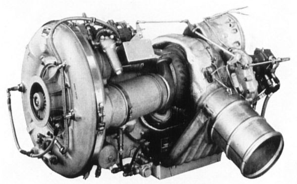
Boeing Model 502-10V (T50-BO-4)
 |
|---|
| Type | Turboshaft, 1-stage centrifugal compressor, 2 combustion chambers, 1-stage gas generator turbine, 1 stage free power turbine. Military engine, for remote control. |
| Compressor | 2-piece aluminum alloy casing. Annular air intake. Single-entry impeller mounted on main shaft front supported in slipper thrust bearing and journal bearings between impeller and rear-mounted turbine wheel. Pressure ratio 4.55:1, and air mass flow 4.3 lb (1.9 kg)/sec @ 37,000 rpm. |
| Combustor | 2 parallel direct flow combustion chambers each with 1 downstream-type fuel burner. |
| Turbine (gas generator) | Steel casing with solid nozzle vanes. 1st-stage turbine wheel with inserted steel blades, bolted to main shaft rear. |
| Turbine (power) | 2nd-stage free turbine wheel with inserted steel blades, mounted on drive shaft supported in journal, slipper thrust and sleeve bearings. Connected to reduction gearbox at engine rear. Turbine exhaust temperature 1,100°F (590°C) @ 28,500 rpm. |
| Exhaust | Fixed area outlet. Bifurcated exhaust ducts from free turbine. |
| Power outlet | Reduction gear 0.21:1 (4.76:1). Output shaft 6,000 rpm max. |
| Control system | Mechanical. Power turbine governor. Constant speed engine. |
| Fuel system | 1 Pesco 022816-030-01 fuel pump, 600 psi (42 kg/cm²). Woodward 1173 flow control with acceleration limiter in unit. |
| Lubrication | Return system. Pump, 60 psi (4.2 kg/cm²). Integral oil tank. |
| Accessories | Electric starter-generator. Bendix-Scintilla TCN-2017 high energy ignition. 2 igniters. |
| Diameter, length | 24.0" (610 mm), 40.0" (1,016 mm) |
| Frontal area | 3.1 ft² (0.29 m²) |
| Weight | 319 lb (145 kg) |
| Power/weight ratio | 0.84 shp/lb (1.85 shp/kg) |
| Fuel specification | MIL-J-5624, JP-4, JP-5 |
| Fuel consumption (normal) | 1.06 lb/shp/hr (480 g/shp/hr) |
| Oil specification | MIL-L-7808 (3.0 cs viscosity) |
| Oil consumption | 0.30 lb/hr (136 g/hr) |
| Rating (military) | 270 shp @ 28,500 power turbine rpm, static |
| Rating (max. cont.) | 240 shp @ 28,500 power turbine rpm, static |
| 502-10VB: Similar to T50-BO-4. 325 shp @ 26,700 power turbine rpm. |
| 502-1OVC (T50-BO-8): Similar to T50-BO-4. 300 shp @ 28,500 power turbine rpm. |
|
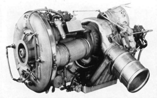
Boeing Model 502-10VC (T50-BO-8A)
 |
|---|
| Type | Turboshaft, 1-stage centrifugal compressor, 2 combustion chambers, 1-stage gas generator turbine, 1-stage free power turbine. Military engine. |
| Compressor | 2-piece aluminum alloy casing. Axial air intake. Single-entry impeller spline-mounted on front end of shaft supported in plain bearings and with slipper-type thrust bearings between impeller and 1st-stage turbine wheel. Pressure ratio 4.77:1. Air mass flow 4.1 lb (1.9 kg)/sec @ 38,500 rpm. |
| Combustor | 2 parallel through-flow combustion chambers, each with 1 Delavan simplex fuel nozzle. Downstream injection. |
| Turbine (gas generator) | Steel casing with solid nozzle vanes. 1st-stage turbine wheel with inserted blades, integral with compressor shaft. |
| Turbine (power) | 2nd-stage free turbine wheel with inserted blades, attached to drive shaft supported in plain bearings and with slipper-type thrust bearings, connected to reduction gearbox at engine rear. Turbine exhaust temperature 1,180°F (638°C) @ 28,500 rpm. |
| Exhaust | Fixed area outlet. Dual exhaust ducts from power turbine, integral with eductor outlets from oil cooler. |
| Power outlet | Reduction gear 0.209:1 (4.79:1). Output shaft 6,000 rpm. |
| Control system | Hydro-mechanical type. Power turbine governor. Constant speed. |
| Fuel system | 1 Pesco 022816-030-01 fuel pump, 1,000 psi (70 kg /cm²). Woodward 1173 fuel control with acceleration limiter in unit. |
| Ignition system | G.L.A. 41669 high-tension ignition. 2 combination high-tension/glow-coil igniters. |
| Lubrication | Return system. 2 pumps, 50 psi (3.5 kg/cm²). Wet sump with integral tank. Oil-to-air cooler attached to exhaust gas-operated air-eductor system integral with engine. Filter. |
| Accessories | Electric starter-generator. |
| Diameter, length | 24.0" (610 mm), 40.0" (1,016 mm) |
| Frontal area | 3.1 ft² (0.29 m²) |
| Weight . | 334 lb (151 kg) |
| Power/weight | 0.90 hp/lb (1.98 shp/kg) |
| Fuel specification | MIL-J-5624, JP-4, JP-5 |
| Fuel consumption (normal) | .0.98 lb/shp/hr (444 g/shp/hr) |
| Oil specification | MIL-L-7808 (3.0 cs viscosity) |
| Oil consumption | 0.30 lb/hr (136 g/hr) |
| Rating (military) | 300 shp @ 28,380 power turbine rpm, static |
| Rating (normal) | 270 shp @ 28,600 power turbine rpm, static |
| Application | 1 in Gyrodyne QH-50C DASH helicopter with remote control. |
|
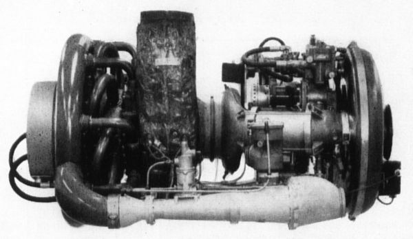
Boeing Model 502-11
 |
|---|
| Type | Gas turbine air compressor with gas producer and output compressor sections without mechanical connection. |
| Compressor (gas producer) | 1-stage centrifugal type. Air intake silencer. 2-piece aluminum alloy casing with integral diffuser, and 2 axial outlets. 2-piece aluminum alloy impeller with 19 vanes. Pressure ratio 4.25:1. Air mass flow 4.0 lb (1.8 kg)/sec @ 36,000 rpm |
| Combustor (gas producer) | 2 interconnected tubular combustion chambers with 2 adapters. 1 fuel burner in each adapter with downstream injection. |
| Turbine (gas producer) | 1-stage axial flow type. Steel casing with 31 solid nozzle vanes. Rotor disc of Timken 16-25-6 alloy with 66 welded-on blades, mounted on compressor-turbine rotor shaft rear end. Gas temperature 1,500°F (816°C) before turbine @ 36,000 rpm. |
| Turbine (output section) | 1-stage axial flow type. Casing attached to gas producer turbine outlet. Rotor disc of Timken 16-25-6 alloy with 50 welded-on blades, has integral shaft driving output compressor. Gas temperature 1,040°F (560°C) after turbine @ 26,000 rpm. |
| Compressor (output section) | 2-stage centrifugal type with pressure regulator. Pressure ratio 3.65:1. Air mass flow 2.1 lb (0.95 kg)/sec @ 26,000 rpm. |
| Exhaust | Fixed area type. Bifurcated manifold connected to output turbine. |
| Control system | Hydro-mechanical type. Manual starting and acceleration. |
| Fuel system | Single fuel manifold. 1 Woodward gear-type fuel pump, 400 psi (28 kg/cm²). Centrifugal governor and acceleration limiter. |
| Lubrication system | Recirculating type. Vane type pump, 60 psi (4.2 kg/cm²). |
| Accessories | Electric starter. Bendix-Scintilla capacitance discharge ignition system with 1 high-energy unit. 2 igniter plugs. |
| Width, height | 25.0" (635 mm), 26.0" (660 mm) |
| Length (as shown) | 47.7" (1,212 mm) |
| Weight | 330 lb (150 kg) |
| Fuel specification | MIL-F-5572, MIL-F-5624A, gasoline, kerosene |
| Oil specification | MIL-O-2104 (SAE 10) (11.6 cs viscosity at 100°C) |
| Fuel consumption (normal) | 235 lb/hr (107 kg/hr) |
| Oil consumption (normal) | 0.10 lb/hr (0.04 kg/hr) |
| Output | 1,570 ft³ (43 m³)/min or 2.0 lb (0.9 kg)/sec, of air at 51 psi (3.6 kg/cm²) @ 36,000 rpm |
| Application | Air compressor units suitable for in-flight air supply, or for ground servicing large jet aircraft. |
| Boeing Model 502-7B: Similar to 502-11. Output 1,175ft³ (33 m³)/min., or 1.5 lb (0.7 kg)/sec of air at 53 psi (3,7 kg/cm²) @ 36,000 rpm. |
|
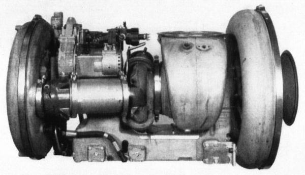
Boeing Model 502-11B
 |
|---|
| Type | Turbo-compressor with gas producer section comprising 1-stage centrifugal compressor, 2 combustion chambers and 1-stage turbine, and compressed air output section comprising 1-stage free turbine and 1-stage centrifugal compressor. |
| Compressor | 1-stage centrifugal flow type. 2-piece aluminum alloy casing. 2-piece single-entry aluminum alloy impeller with 19 vanes, mounted on drive shaft front supported in 2 slipper bearings. Pressure ratio 4.25:1, and air mass flow 4.0 lb (1.8 kg)/ sec @ 36,000 rpm. |
| Combustor | 2 interconnected tubular combustion chambers. 1 fuel burner in each flame tube with downstream injection. |
| Turbine (gas producer) | 1-stage axial flow type. Steel casing with 31 solid nozzle vanes. Turbine wheel of Timken 16-25-6 alloy with 66 welded-on blades, mounted on drive shaft rear end. Turbine inlet temperature 1,500°F (816°C). Exhaust temperature 1,075°F (579'C) @ 36,000 rpm. |
| Turbine (power) | 1-stage axial flow free turbine. Casing connected to gas producer turbine. Turbine wheel of Timken 16-25-6 alloy with 50 welded-on blades, mounted on output compressor shaft. Exhaust temperature 1,040°F (560°C) @ 30,000 rpm. |
| Compressor (output) | 1-stage centrifugal flow type. Single-entry impeller. Pressure ratio 3.65:1. Air mass flow 2.1 lb (0.95 kg)/sec @ 36,500 rpm. |
| Exhaust | Fixed area outlet. Bifurcated exhaust ducts behind free turbine. |
| Control system | Mechanical type. Automatic starting control. Pressure regulator. |
| Fuel system | 1 Pesco gear-type pump, 600 psi (42 kg/cm²). Woodward flow control with acceleration limiter governor for rpm control. |
| Lubrication | Return system. Gear-type pump, 60 psi (4.2 kg/cm²). |
| Accessories | Electric starter-generator. Bendix-Scintilla TCN-2015 high-energy ignition system. 2 igniter plugs. |
| Width, height | 28.5" (724 mm), 27.0" (686 mm) |
| Length | 50.0" (1,270 mm) |
| Weight | 375 lb (170 kg) |
| Power/weight ratio | 0.56 air hp/lb (1.23 air hp/kg) |
| Fuel specification | MIL-G-5512, MIL-F-5624, gasoline, JP-4 |
| Fuel consumption (normal) | 245 lb/hr (111 kg/hr) |
| Oil specification | SAE 10 (6.2 cs viscosity) |
| Oil consumption | 0.10 lb/hr (45 g/hr) |
| Rating (max. cont.) | 210 air hp @ 36,000 rpm, sea level |
| Output (max. cont.) | 2.1 lb (0.95 kg) air/sec, at 57 psi (4.0 kg/cm³) @ 36,000 rpm |
| Application | Air compressor unit for gas turbine starter carts. |
|
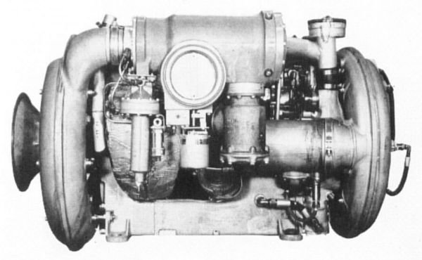
Boeing Model 502-12B
 |
|---|
| Type | Turbo-compressor. 1-stage centrifugal compressor, 2 combustion chambers, 1-stage gas generator turbine, 1-stage free power turbine driving 1-stage auxiliary compressor. |
| Compressor | 2-piece aluminum alloy casing. Annular air intake. Single-entry (main) impeller mounted on main shaft front supported in slipper thrust and journal bearings between impeller and rear-mounted turbine wheel. Pressure ratio 4.25:1. Air mass flow 4.0 lb (1.8 kg)/sec @ 36,500 rpm. |
| Combustor | 2 parallel combustion chambers. Downstream-type fuel burners. |
| Turbine (gas generator) | Steel casing with hollow nozzle vanes. 1st-stage turbine wheel with inserted steel blades, bolted to main shaft rear. |
| Turbine (power) | 2nd-stage free turbine wheel with inserted steel blades, mounted on drive shaft supported in journal and slipper thrust bearings, and connected to auxiliary compressor. Turbine exhaust temperature 1,040°F (560°C) @ 30,000 rpm. |
| Exhaust | Fixed area outlet. Single or bifurcated exhaust ducts. |
| Compressor (auxiliary) | 2-piece aluminum alloy casing with radial and axial diffusers. Single-entry impeller mounted on drive shaft rear. Pressure ratio 3.65:1. Air mass flow 2.1 lb (0.95 kg)/sec @ 30,000 rpm. |
| Control system | Mechanical type. Automatic starting control. Pressure regulator. |
| Fuel system | 1 Pesco 022816-030-01 fuel pump, 600 psi (42 kg/cm²), and Woodward 1173 proportional flow control with acceleration limiter in unit. |
| Lubrication | Return system. Pump, 60 psi (4.2 kg/cm²). |
| Accessories | Electric starter-generator. Bendix-Scintilla TCN-2015 high-energy ignition. 2 igniters. |
| Width, height | 28.5" (724 mm), 27.0" (686 mm) |
| Length | 50.0" (1,270 mm) |
| Weight | 410 lb (186 kg) |
| Power/weight ratio | 0.50 air hp/lb (1.10 air hp/kg) |
| Fuel specification | MIL-G-5572, MIL-J-5624, gasoline, JP-4 |
| Fuel consumption (normal) | 1.19 lb/air hp/hr (539 g/air hp/hr) |
| Oil specification | SAE 10 (6.2 cs viscosity ) |
| Oil consumption | 0.10 lb/hr (45 g/hr) |
| Rating (max. cont.) | 180 air hp @ 37,000 gas generator turbine rpm, sea level |
| Output (max. cont.) | 1.96 1b (0.89 kg) air/sec, at 52 psi (3.7 kg/cm²) @ 37,000 rpm |
| Application | Air compressor unit for aircraft gas turbine starter carts. |
| 502-11 BA: Similar to 502-12B. 205 air hp, or 2.1 lb (0.95 kg) air/sec at @ 36,500 rpm. Used in MA-1A mobile starter. |
|
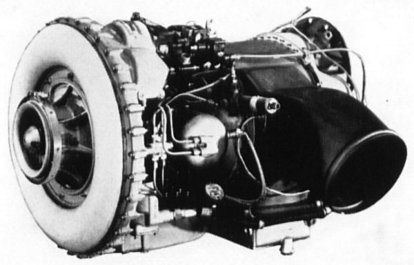
Boeing Model 502-14 (T50-BO-10)
 |
|---|
| Type | Turboshaft, 1-stage centrifugal compressor, 2 combustion chambers, 1-stage gas generator turbine, 1-stage free power turbine. Military engine. |
| Compressor | 2-piece aluminum alloy casing. Annular air intake. Single-entry impeller mounted on front of main shaft supported in slipper thrust bearing and journal bearings between impeller and rear-mounted turbine wheel. Pressure ratio 4.35:1. Air mass flow 4.1 lb (1.8 kg)/sec @ 37,400 rpm. |
| Combustor | 2 horizontally-opposed reverse flow combustion chambers, each with 1 downstream-type fuel burner. |
| Turbine (gas generator) | Steel casing with solid nozzle vanes. 1st-stage turbine wheel inserted steel blades bolted to main shaft rear. |
| Turbine (power) | 2nd-stage free turbine wheel, inserted steel blades, mounted on drive shaft supported in journal, slipper thrust and sleeve bearings, and connected to reduction gearbox at engine rear. Turbine exhaust temperature 1,140°F (598°C) @ 28,600 rpm. |
| Exhaust | Fixed area outlet. Bifurcated exhaust ducts from free turbine. |
| Power outlet | Reduction gear, 0.21:1 (4.76:1). Output shaft 6,000 rpm max. |
| Control system | Pneumatic type. Power turbine governor. Constant speed engine. |
| Fuel system | 1 Vickers 4V317L002 fuel pump, 600 psi (42 kg/cm²), Bendix Products DP-A4 flow control with acceleration limiter, and AL-J4 output speed governor in unit. |
| Lubrication | Return system. Pump, 60 psi (4.2 kg/cm²). Integral oil tank. |
| Accessories | Electric starter-generator. Bendix-Scintilla TCN-2015 high energy ignition. 2 igniters. |
| Diameter, length | 22.5" (572 mm), 38.9" (988mm) |
| Frontal area | 2.8 ft² (0.26 m²) |
| Weight | 215 lb (97 kg) |
| Power/weight ratio | 1.53 shp/lb (3.37 shp/kg) |
| Fuel specification | MIL-J-5624, JP-4, JP-5 |
| Fuel consumption (normal) | 0.87 lb/shp/hr (395 g/shp/hr) |
| Oil specification | MIL-L-7808 (3.0 cs viscosity) |
| Oil consumption | 0.30 lb/hr (136 g/hr) |
| Rating (military) | 330 shp @ 28,600 power turbine rpm, static |
| Rating (max. cont.) | 300 shp @ 28,600 power turbine rpm, static |
|
Boeing Model 520-2 (T60-BO-2)
t.jpg)
 |
|---|
| Type | Turboshaft with 1-stage centrifugal compressor, 2 combustion chambers, 2-stage turbine, shaft power output. |
| Compressor | 1-stage centrifugal flow type. 4 horizontal air intakes for double-entry impeller with 19 vanes each side, mounted on shaft supported in 1 slipper-type thrust bearing at front end where connected to reduction gearbox, and in 2 slipper bearings at rear end ahead of turbine wheel. Scroll type collector with 8 ducts from diffuser to combustor. Pressure ratio 6.6:1, and air mass flow 5.5 lb (2.5 kg)/sec @ 43,000 rpm. |
| Combustor | 2 interconnected reverse flow combustion chambers with Inconel liners. 1 fuel burner in each combustion chamber. |
| Turbine (gas producer) | 1-stage radial inflow type. Steel casing integral with combustor plenum chamber. 20 solid nozzle vanes of 310 alloy steel. Turbine wheel of Inconel X alloy with 15 integral vanes, mounted on compressor-turbine drive shaft rear end. |
| Turbine (output) | 1-stage axial flow free turbine. Casing connected to gas producer turbine with 31 stator blades of 310 alloy steel. Turbine wheel of HS31 alloy steel with 58 blades, mounted on end of drive shaft to reduction gearbox and supported in 2 slipper bearings. Turbine exhaust temperature 900°F (482°C) @ 43,000 rpm. |
| Exhaust | Fixed area outlet with duct adjustable to any position. |
| Power outlet | Reduction gearbox at unit front with 6,000 rpm output shaft. |
| Control system | Mechanical type. Automatic starting control. Pressure regulator. |
| Fuel system | 1 Pesco 022816-030 gear type pump, 350 psi (25 kg/cm²). Woodward proportional flow control with acceleration limiter. |
| Lubrication | Return system. Gear-type pump, 50 psi (3.5 kg/cm²). |
| Accessories | Electric starter-generator. Bendix-Scintilla TCN-1102 high-energy ignition system. 2 igniter plugs. |
| Width, height | 25.0" (635 mm), 26.0" (660 mm) |
| Length | 57.2" (1,453 mm) |
| Weight | 350 lb (159 kg) |
| Power/weight ratio | 1.14 shp/lb (1.14 kgp/kg) |
| Fuel specification | MIL-F-5624, JP-4, JP-5 |
| Fuel consumption (normal) | 252 lb/hr (114 kg/hr) |
| Oil specification | MIL-L-7808 (synthetic) (3.0 cs viscosity (Turbo 15)) |
| Oil consumption | 0.06 lb/hr (27 g/hr) |
| Rating (maximum) | 400 shp @ 43,000 rpm, sea level |
| Rating (max. cont.) | 350 shp @ 42,000 rpm, sea level |
| Application | Shaft power unit for helicopters. |
|
Boeing Model 520-6
 |
|---|
| Type | Turboshaft, 1-stage centrifugal compressor, 2 combustion chambers, 1-stage gas generator turbine, 1-stage free power turbine. |
| Intake | 2 horizontal air intakes on each side towards engine front. |
| Compressor | 2-piece aluminum alloy casing. Double-entry impeller mounted on front of main shaft supported in 1 slipper thrust bearing and 2 journal bearings between impeller and turbine wheel mounted on shaft rear. 8 exterior air ducts led backward from diffuser to combustor plenum chamber. Pressure ratio 6.5:1. Air mass flow 5.3 lb (2,4 kg)/sec @ 44,000 rpm. |
| Combustor | 2 reverse flow combustion chambers. Delavan fuel burners. |
| Turbine (gas generator) | Radial inflow type. Steel casing integral with combustor plenum chamber. Solid nozzle vanes. Turbine wheel has integral vanes. |
| Turbine (power) | Axial flow type. Free turbine wheel mounted on drive shaft front supported in 2 journal bearings and 1 slipper thrust bearing. Connected to reduction gearbox at unit rear. Turbine exhaust temperature 1,025°F (551°C) @ 25,000 rpm. |
| Exhaust | Fixed area outlet. Rotatable single tangential outlet duct. |
| Power outlet | Reduction gear 0.249:1 (4.01:1). Output shaft 6,000 rpm max. |
| Control system | Mechanical type. Pressure regulator. Constant speed engine. |
| Fuel system | 1 Vickers 4V317L002-9 fuel pump, 600 psi (42 kg/cm²) ; Bendix Products DP-A4 flow control, AL-J4 output speed governor. |
| Lubrication | Return system. Pump, 50 psi (3.5 kg/cm²). Integral oil tank. |
| Accessories | Electric starter-generator. Bendix-Scintilla TCN-1014 high energy ignition. 2 torch igniters with Delavan fuel nozzles. |
| Diameter, length | 25.0" (635 mm), 55.0" (1,397 mm) |
| Frontal area | 3.4 ft² (0.32 m²) |
| Weight | 250 lb (113 kg) |
| Power/weight ratio | 2.20 shp/lb (4.84 shp/kg) |
| Fuel specification | MIL-J-5616, MIL-F-5624, JP-1, JP-4, JP-5 |
| Fuel consumption (normal) | 0.65 lb/shp/hr (295 g/shp/hr) |
| Oil specification | MIL-L-7808 (3,0 cs viscosity) |
| Oil consumption | 0.20 lb/hr (91 g/hr) |
| Rating (military) | 550 shp + 35 lbt (11 kgp) @ 26,000 power turbine rpm, static |
| Rating (max. cont.) | 500 shp + 32 lbt (10 kgp) @ 26,000 power turbine rpm, static |
| 520-2 (T60-BO-2A): Turboshaft. Turbine inlet temperature 1,620°F (882°C). Weight 315 lb (143 kg). Fuel Consumption 0.76 lb (345 g)/shp/hr. Rating (military) 430 shp + 31 lbt (14 kgp) @ 24,000 rpm. Rating (normal) 375 shp |
| 520-4: Turboprop. 495 ehp, or 475 shp + 51 lbt (23 kgp) @ 24,000 rpm. |
| 520-8: Turboprop. 572 ehp, or 550 shp + 55 lbt (25 kgp) @ 24,000 rpm. |
|
Boeing Model 550-1 (T50-B0-10)
t.jpg)
|
|---|
| Type | Turboshaft, 1-stage axial and 1-stage centrifugal compressor, 2 combustion chambers, 1-stage gas generator turbine, 1-stage free power turbine. Military engine. |
| Compressor | 2-piece aluminum alloy casing. Axial air intake. Radial and axial diffusers. Rotor comprises 1 disc with axial blades and 1 single-entry impeller with radial vanes spline-mounted on front end of shaft supported in plain bearings and with slipper-type thrust bearings between impeller and 1st-stage turbine wheel. Pressure ratio 5.69:1. Air mass flow 4.1 lb (1.8 kg)/sec @t 39,400 rpm. |
| Combustor | 2 horizontally-opposed reverse flow combustion chambers, each with 1 Delavan dual-orifice fuel nozzle. |
| Turbine (gas generator) | Steel casing with solid nozzle vanes. 1st-stage turbine wheel with inserted blades, integral with compressor shaft. |
| Turbine (power) | 2nd-stage free turbine wheel with inserted blades, attached to drive shaft supported in plain bearings and with slipper-type thrust bearings, connected to reduction gearbox at engine rear. Turbine exhaust temperature 1,085°F (586°C) @ 28,600 rpm. |
| Exhaust | Fixed area outlet. Dual exhaust ducts from power turbine, integral with eductor outlets from oil cooler. |
| Power outlet | Reduction gear, 0.188:1 (5.32:1). Output shaft 6,000 rpm. |
| Control system | Pneumatic type. Power turbine governor. Constant speed engine. |
| Fuel system | 1 Vickers 4V317L003 fuel pump, 400 psi (28 kg/cm²), Bendix Products DP-A4 flow control with acceleration limiter, torque limiter, and shut-off valve in unit. |
| Ignition system | G.L.A. 41997 high-tension ignition. 2 igniters. |
| Lubrication | Return system. 2 pumps, 50 psi (3.5 kg/cm²). Wet sump with integral tank. Oil-to-air cooler attached to exhaust gas-operated air-eductor system integral with engine. Filter. |
| Accessories | Air impingement starting system. |
| Diameter, length | 22.5" (572 mm), 37.5" (952 mm) |
| Frontal area | 2.8 ft² (0.26 m²) |
| Weight | 243 lb (110 kg) |
| Power/weight | 1.36 shp/lb (3.00 shp/kg) |
| Fuel specification | MIL-J-5624, JP-4, JP-5 |
| Fuel consumption (normal) | .0.81 lb/shp/hr (367 g/shp/hr) |
| Oil specification | MIL-L-7808 (3,0 cs viscosity) |
| Oil consumption | 0.30 lb/hr (136 g/hr) |
| Rating (military) | 330 shp @ 31,650 power turbine rpm, static |
| Rating (normal) | 300 shp @ 28,600 power turbine rpm, static |
| Application | 1 in Gyrodyne QH-50D DASH helicopter with remote control. |
|
Boeing Model 550-1 (T50-BO-12)
t.jpg) |
|---|
| Type | Turhoshaft, 2-shaft, 1-stage axial and 1stage centrifugal compressor, 2 combustion chambers, 1-stage gas generator turbine, 1-stage free power turbine. Military. |
| Compressor | 2-piece aluminum alloy casing. Axial air intake. Radial and axial diffusers. Rotor comprises 1 disc with axial blades and 1 single-entry impeller with radial vanes spline-mounted on front end of shaft supported in plain bearings and with slipper-type thrust hearings between impeller and 1st-stage turbine wheel. Pressure ratio 6.1:1 Air mass flow 4.5 1b (2.0 kg)/see @ 39,600 rpm. |
| Combustor | 2 horizontally-opposed reverse flow combustion chambers, each with 1 Delavan dual-orifice fuel nozzle. |
| Turbine (gas generator) | Steel casing with solid nozzle vanes. 1st-stage turbine wheel with inserted blades, integral with compressor shaft. |
| Turbine (power) | 2nd-stage free turbine wheel with inserted blades, attached to power drive shaft supported in plain hearings and with slipper-type thrust bearings, connected to reduction gearbox at engine rear. Turbine exhaust temperature 1,045°F (563°C) @ 32,000 rpm. |
| Exhaust | Fixed area outlet. Dual exhaust ducts from power turbine, integral with eductor outlets from oil cooler. |
| Power outlet | Reduction gear, 0.188:1 (5.34:1). Output shaft 6,000 rpm. |
| Control system | Pneumatic type. Power turbine governor. Constant speed engine. |
| Fuel system | 1 Vickers 4V317L005 fuel pump, 850 psi (60 kg/cm²). Bendix Products DP-4A fuel control with acceleration limiter and shut-off valve in unit mount. |
| Ignition system | G.L.A. 41997 high-energy ignition. 2 igniters. |
| Lubrication | Return system. 2 pumps, 50 psi (3.5 kg/cm²). Wet sump with integral tank. Oil-to-air cooler attached to exhaust gas-operated air-eductor system integral with engine. Filter. |
| Starter | Air impingement or electric starter. |
| Diameter, length | 22.5" (572 mm), 37.5" (952 mm) |
| Frontal area | 2.8 ft² (0.26 m²) |
| Weight | 250 lb (113 kg) |
| Power/weight | 1.46 shp/lb (3.21 shp/kg) |
| Fuel specification | MIL-J-5624, JP-4, JP-5 |
| Fuel consumption ( normal ) | 0.82 lb/shp/hr (372 g/shp/hr) |
| Oil specification | MIL-L-7808 (3.0 cs viscosity) |
| Oil consumption | 0.30 lb/hr (136 g/hr) |
| Rating (military) | 365 shp @ 31,650 power turbine rpm, static |
| Rating (normal) | 340 shp @ 32,000 power turbine rpm, static |
| Application | 1 in Gyrodyne QH-50D DASH helicopter with remote control. |
|
Boeing Model 550-1-22C (T50-BO-10)
 |
|---|
| Type | Turboshaft, 1-stage axial and 1-stage centrifugal compressor, 2 combustion chambers, 1-stage gas generator turbine, 1-stage free power turbine. Commercial engine. |
| Compressor | 2-piece aluminum alloy casing. Axial air intake. Radial and axial diffusers. Rotor comprises 1 disc with axial blades and 1 single-entry impeller with radial vanes spline-mounted on front end of shaft supported in plain bearings and with slipper-type thrust bearings between impeller and 1st-stage turbine wheel. Pressure ratio 5.92:1, and air mass flow 4.46 lb (2.0 kg)/sec/ @ 40,000 rpm. |
| Combustor | 2 horizontally-opposed reverse flow combustion chambers, each with 1 dual-orifice fuel nozzle. Downstream injection. |
| Turbine (gas generator) | Steel casing with solid nozzle vanes. 1st-stage turbine wheel with inserted blades, integral with compressor shaft. |
| Turbine (power) | 2nd-stage free turbine wheel with inserted blades, attached to drive shaft supported in plain bearings and with slipper-type thrust bearings, connected to reduction gearbox at rear. Turbine exhaust temperature 1,100°F (594°C) @ 31,900 rpm. |
| Exhaust | Fixed area turbine outlet. Single or dual ducts, 360° rotation. |
| Power outlet | Reduction gear 0.188:1 (5.32:1). Output shaft 6,000 rpm. |
| Control system | Pneumatic type. Power turbine governor. Constant speed engine. |
| Fuel system | 1 Vickers 4V317L003 fuel pump, 400 psi (28 kg/cm²), Bendix Products DP-A4 flow control with inlet temperature compensation, acceleration limiter, and shut-off valve in unit. |
| Ignition system | G.L.A. 41997 high-tension ignition. 2 igniters. |
| Lubrication | Return system, 50 psi (3.5 kg/cm²). Wet sump. Integral tank. |
| Accessories | Electric starter-generator. |
| Diameter, length | 22.5" (572 mm), 36.8" (934 mm) |
| Frontal area | 2.8 ft² (0.26 m²) |
| Weight | 211 lb (96 kg) |
| Power/weight | 2.01 shp/lb (4.42 shp/kg) |
| Fuel specification | ASTM A-1, MIL-J-5624, JP-1, JP-4, JP-5 |
| Fuel consumption (normal) | 0.75 lb/shp/hr (340 g/shp/hr) |
| Oil specification | MIL-L-7808 (3.0 cs viscosity) |
| Oil consumption | 0.30 lb/hr (136 g/hr) |
| Rating (maximum) | 425 shp @ 31,900 power turbine rpm, static |
| Rating (max. cont.) | 385 shp @ 31,650 power turbine rpm, static |
| Application | Commercial helicopters. This engine is the commercial version of the Boeing T50-BO-10. |
|
Acknowledgements
Many thanks to Douglas Culy for the Boeing Model 540 information and images.
References
Leyes, Richard A. II and William A. Flemming The History of North American Small Gas Turbine Aircraft Engines (Reston, Virginia: AIAA, 1999) 51 -62.
Wilkinson, Paul H. Aircraft Engines of the World (New York, New York: Paul H. Wilkinson, 1948 to 1966/67).


t.jpg)
t.jpg)
t.jpg)
t.jpg)
t.jpg)
t.jpg)
t.jpg)



t.jpg)
t.jpg)
t.jpg)
t.jpg)


