SR-71 Propulsion System
P&W J58 Engine (JT11D-20)
by Peter Law
Presented 9 Oct 2013 at the 10th Annual AEHS Convention
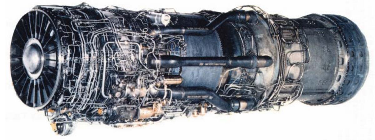
Pratt & Whitney J58 – One of the Best Jet Engines Ever Built |
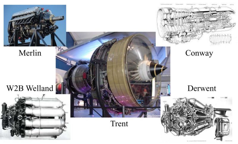 |
| Rolls-Royce Milestone Engines |
The Airplane
 |
 |
 |
 |
| Pratt & Whitney J58 Under Test |
Lockheed SR-71 |
Lockheed SR-71 |
Lockheed SR-71 |
SR-71 General Characteristics
- Two Place High-Altitude High-Speed Reconnaissance Aircraft
- Developed In Early 1960s By Kelly Johnson, Lockheed "Skunk Works" – in Burbank, California (Advanced Development Projects -ADP)
- Delta Wing Configuration
- Crew Of Two: Pilot And Reconnaissance Systems Officer (RSO) – Seated In Tandem Arrangement
- Inflight Refueling Capability -Crew Endurance Is Limit
- Aircraft Length 1s 107 Feet, Wing Span Is 55 Feet, Height Is 18 Feet
- Takeoff Weight Is 140,000 Pounds; 80,000+ Pounds Of Fuel
- 93% Of Vehicle Structure And Skin Is Titanium
- Aircraft Series Known As "Blackbirds"
SR-71 Performance Characteristics
- Cruising Altitude Is Between 74,000 And 85,000 Feet
- Cruising Speed Is Mach 3.2+, 2100+ MPH, 3100+ Feet/Sec
- Range Is 3,000 Miles, 15,000 Miles With Refueling
- Total Flight Time Of All "Blackbird" Aircraft: 53,000+ Hours
- Total Time Above Mach 3.0: 11,000+ Hours (22 Million Miles)
- Powered By Two Pratt & Whitney J58 Turbojet Engines, Each With The Power Of The Queen Mary
- Vehicle Was Designed With Radar Signature Reduction Techniques
SR-71 Flight Records
| Sustained Speed In Level Flight | 7/28/1976 | 2,193.16 MPH | |
| Sustained Altitude In Level Flight | 7/28/1976 | 85,069 Feet | |
| New York to London | 9/1/1974 | 1806.96 MPH | 1 Hr 54 Min 32 Sec |
| London to Los Angeles | 9/13/1974 | 1435.59 MPH | 3 Hr 47 Min 39 Sec |
| USA Coast to Coast | 3/6/1990 | 2124.51 MPH | 1 Hr 7 Min 53.69 Sec |
| Los Angeles to Washington, DC | 3/6/1990 | 2144.83 MPH | 1 Hr 4 Min 19.69 Sec |
| Kansas City to Washington, DC |
3/6/1990 | 2176.08 MPH | 24 Min 58.53 Sec |
| St. Louis To Cincinnati | 3/6/1990 | 2189.94 MPH | 8 Min 31.93 Sec |
| NAA Official Data - 1992 |
General Comments on the SR-71 Propulsion System
- The SR-71 was the finest air breathing jet aircraft ever developed, built, and flown.
- Designed to fly at Mach 3.2, wind tunnel tested to Mach 3 5 and flew missions at Mach 3 3+ at altitudes of 86,000+ feet.
- The P&W J58 (JT11D-20) had the power of the Queen Mary; started life with 30,000 lbT, and ended with 34,000 lbT.
- The “propulsion system” consisted of the air inlet, the air flow control system, the J58 engine, and the exhaust nozzle assembly (part of the airframe).
- The important features of each will be briefly covered, as each part was critical for proper operation of the integrated “propulsion system”.
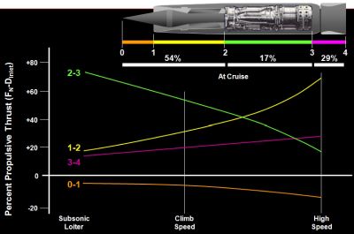
- At Mach 3.2, 54% of the thrust was provided by the inlet (differential pressure between external and internal inlet spike surfaces), 17% by the engine, and 29% by the ejector. The engine acted as a gas generator.
- The engine operates from 4,000 rpm (idle) to 7,400 rpm (max).
 |
 |
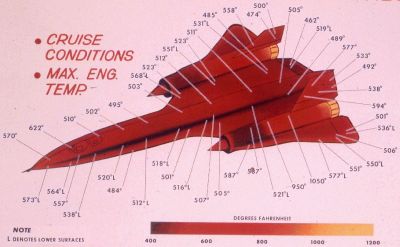
| SR-71 Surface Temperatures |
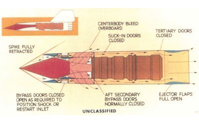
SR-71 Nacelle Airflow |
The Engine
The Pratt & Whitney JT11D-20, Designated “J58” by the Military
- Fuel consumption at a cruising Mach number is approximately 8,000 gallons per hour.
- Fuel is JP-7, which has an extremely low vapor pressure and a very high flash point.
- A special ignition system is used to light this fuel . A pyrophoric chemical – triethylborane (TEB)– ignites the main engine and the afterburner.
- The engine operates in the most hostile environment any engine has ever been subjected to:
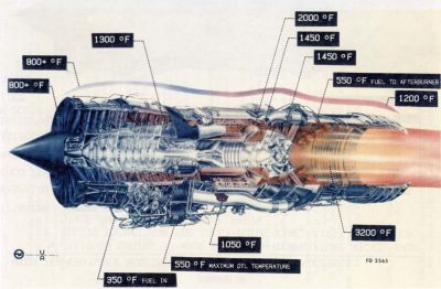
– Air entering the combustor reaches 1,400°F
– Turbine inlet temperature is 2,000°F
– Afterburner section temperature reaches 3200°F
- Ground starting requires using two 300 hp Buick Wildcat racing engines connected to the J58 starter drive.
- At full afterburner power the afterburner glows cherry red.
J58 Design Requirements Were a Leap Into the Unknown
| | Production Engine
Experience
(J57 and J75) | JT111D-20
Design
Requirements |
|---|
| Mach Number | 2.0 for 15 min (J75 only) | 3+ (Continuous) |
Corrected Airflow Turndown Ratio
(Cruise / Maximum) | 90% | 60% |
| Altitude | 55,000 ft | 80,000+ ft |
| Compressor Inlet Temperature | -40°F to 250°F (J75 only) | -40°F to 800°F |
| Combustor Exit Temperature | 1,750°F (Takeoff)
1,550°F (Continuous) | 2,000°F (Continuous) |
| Maximum Fuel Inlet Temperature | 110 - 130°F | 350°F |
| Maximum Lubricant Inlet Temperature | 250°F | 550°F |
| Thrust / Weight Ratio | 4.0 | 5.2 |
| Military Operation | ≤ 30 min | Continuous |
 |
 |
 |
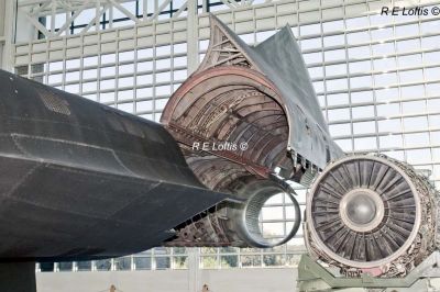
| SR-71 Port Nacelle Open with J58 Along Side |
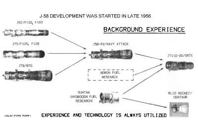
JT11D-20 — A Successful Leap Into the Technical Unknown |
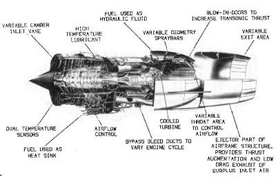
JT11D-20 Innovations |
 |
 |
 |
| Engine and Nacelle Temperatures |
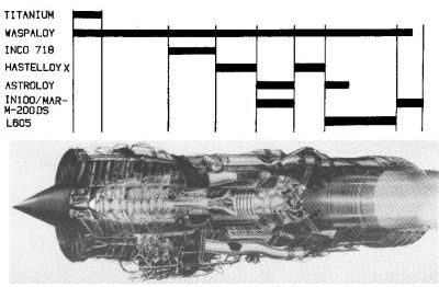
High temperatures required new materials and processes. The JT11D-20 is made from high-temperature nickel-based alloys except for the inlet guide vanes, first compressor stage and gearbox internal parts. |
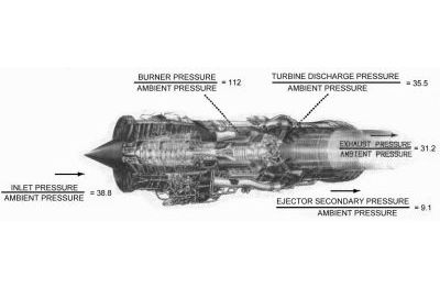
Total Pressures in the Engine and Nacelle During Supersonic Cruise |
 |
 |
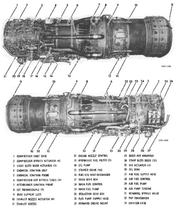
| J58 External Detail |
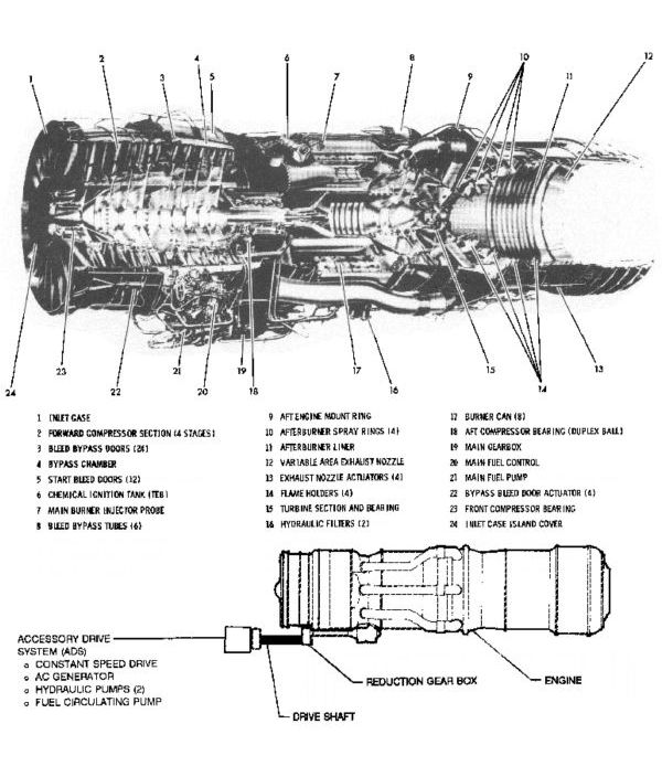
J58 Internal Detail |
SR-71 Inlet Requirements
- High Pressure Recovery
- Minimum Drag
- Airflow Capability Compatible with Engine Airflow Requirements
- Duct Exit Airflow Distortion Acceptable To Engine
- Airflow Supply to Cool Engine and Operate Ejector Nozzle
- Stable Operation
SR-71 Air Inlet Design Drivers
- Match the Air Flow Captured By The Inlet to the Air Flow Required By The Engine for All Conditions
- At Supersonic Cruise, Reduce The Velocity of the Captured Air to About 0.4 Mach Required at the Engine Face
- Maximize Pressure Recovery at the Engine Face While Reducing Velocity
- Minimize The Transient Flow Effects of External Distrubances
- No Fixed Inlet Configuration Can Simultaneously Satisfy These Requirements Over the Entire Flight Envelope and Engine Operating Range
- Variable Inlet Geometry Is Required
 |
 |
 |
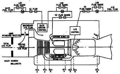
| Schematic of JT11D-20 in Altitude Test Facility |
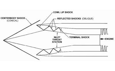
Axi-Symmetric Mixed Compression Inlet Design Concept |
Inlet Bleed and Bypass Arrangement |
 |
| Thrust Production |
 |
| SR-71 Inlet / Exhaust Airflow Patterns |
 |
| Centerbody Bleed Arrangement |
 |
| Forward Bypass |
 |
| Secondary Flow Systems, Cowl Bleed and Aft Bypass |
SR-71 Air Inlet Characteristics
- Axi-Symmetric Mixed Compression Inlet Chosen Because
– Lower Weight, Drag, and Signature of Axi-Symmetric
– Desired Range and Cruise Performance Required Pressure Recoveries Higher Than Possible With An External Compression Inlet At Mach 3.0+
- Mixed Compression Inlets Can Attain High Pressure Recovery Above Mach 2 2
– If Normal Shock Can Be Kept at The Design Location Just Downstream of the Minimum Cross Sectional Flow Area (Inlet Throat)
– If Normal Shock Can Be Maintained Near The Design Location During Internal Or External Flow Perturbations
- If Normal Shock Cannot Be Maintained Downstream of the Throat Above Mach 2.2
– Inlet Is Said to be “Unstarted”
– Normal Shock Pops Out and Stabilizes Forward of the Inlet Lip
– Pressure Recovery, Air Flow, and Thrust Drop to Low Levels
– Drag Increases Significantly
– Inlet Must Be Restarted as Fast as Possible to Prevent Engine Damage and Minimize Airplane Yaw Transient
Inlet System
- The inlet has a translating 26° cone that acts as the initial deceleration or compression surface producing a series of shock waves up to the inlet throat.
- The shock train ends with a final terminal or normal shock followed by a subsonic diffuser.
- The inlet&rsquot;s purpose is to supply the air required by the engine at the highest pressure recovery and lowest drag, with a minimum of distortiondistortion. This is not as simple as it sounds!
- A turbojet engine is a constant volume machine. This means that regardless of flight speed – from M = 0 to cruise speed – the speed or Mach number entering the engine is relatively constant, between M = 0.3 and 0.5
Air Inlet
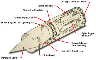
- The SR-71 engine air inlet is a mixed external and internal compression, axi-symmetric inlet, with gradual isentropic compression approaching the throat.
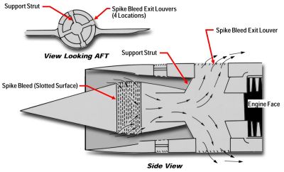
- The boundary layer that builds up on the centerbody is removed ahead of the terminal shock through a porous bleed.
- This bleed passes overboard through louvers at the ends of the centerbody support struts.
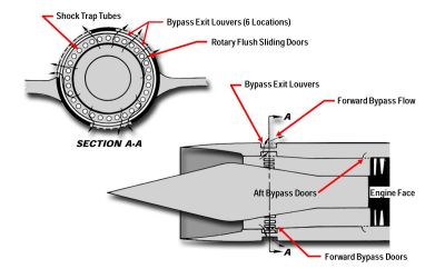
- Forward bypass doors, located close to the throat, match the inlet to the engine, bypassing air overboard.
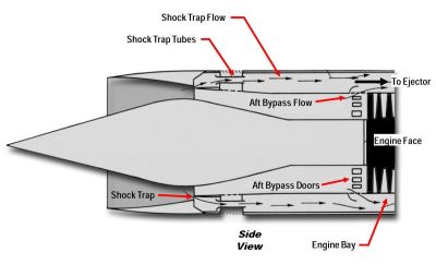
- The cowl bleed is a “shock trapshock trap” ram bleed that supplies air through tubes across the bypass door region into the engine secondary passage, where it is used for cooling, and fed through to the engine ejector.
- Aft bypass flow joins the cowl bleed flow and passes through the engine ejector.
- This bypass was installed to provide sufficient flow to permit engine operation at idle.
- During acceleration, aft bypass is used to reduce the pass is used to reduce the forward overboard bypass with its attendant drag.
Inlet Spike
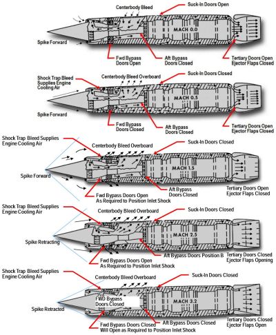
- The inlet spikes regulate the amount of air entering the inlet by moving progressively rearwards as the aircraft’s speed increases
– The fully forward position, which the spike maintains up to Mach 1.4
– The spike at the limit of its 26-inch aft translation
– The configuration of the inlet at Mach 3 and above.
- At this point the capture area has increased by 112%, while the throat diameter at the point of minimum cross-section further down the intake has decreased by 54% in order to hold the tri-sonic shockwave in the correct position
- At Mach 2.2 the inlet produces 13% of the overall thrust, the engine and ejector accounting for 73% and 14% respectively
– The corresponding figures at maximum cruising speed, Mach 3+, are 54%, 17%, and 29%
– most of the thrust is developed by the inlet spike
Inlet Configuration and Control
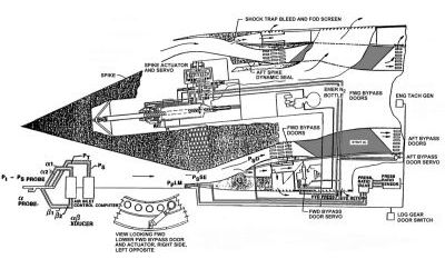
- The inlet utilizes Digital Automatic Flight and Inlet Control System (DAFICS) computers for spike and bypass door control.
- Spike movement is controlled by Mach number, angle of attack, angle of yaw, and load factor.
- The terminal shock position is controlled and regulated by forward and aft bypass doors, which match the inlet air swallowing capability to the engine requirement.
- The compression ratio at cruise is 40 to 1.
- At cruise, each inlet swallows approximately 100,000 cubic feet of air per second – equivalent to two million people breathing on the ground.
- Inlets are canted inboard 3.2° to compensate for the effect of chine and fuselage.
- Inlets are canted down 5.6° to compensate for cruise angle of attack.
SR-71 Air Inlet Control System Functions
- Forward bypass doors are open with the gear down, close when landing gear retracts, but begin to open again at Mach 1 4 to dump excess flow captured by inlet.
- The spike is full forward at low Mach numbers and is progressively retracted for Mach numbers above 1.6.
- The control system positions the spike as a function of Mach number with angle of attack, slideslip, and normal acceleration bias.
- The normal shock moves downstream of the inlet throat (inlet starts) at aproximately Mach 1.7.
- Above Mach 2.2 bypass doors modulate as required to keep the normal shock at the design location.
- If an unstart occurs in one inlet above Mach 2.3, both spikes are driven to the forward position and the forward bypass doors are opened to obtain a restart and minimize yaw transients.
- Aft bypass doors are scheduled manually to provide cooling air to engine bay and ejector.
Ejector Nozzle
- The last part of the propulsion system is the ejector.
– The ejector performs the reverse function of the inlet.
– It accelerates the air coming out of the turbine at M = 0.4 up to M = 3.0+
– The exit velocity must match or exceed the flight speed, therefore the variable exit flaps stay fully closed until about M = 1.2, and are fully open at about M = 2.4
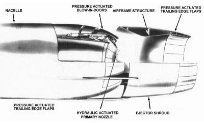
- The primary nozzle is a ring of blow-in doors that provide tertiary air to fill in the ejector at Mach numbers below 1.2.
– Tertiary air is provided by suck-in doors around the nacelle, augmented by the cowl (shock trap bleed and aft bypass bleed)
aft bypass bleed)
– The main ejector is supported downstream on streamlined struts and a ring of Rene 41 steel alloy on which are hinged free-floating trailing edge flaps of Hastelloy X
 |
 |
| SR-71 Air Inlet Control Components |
Blow-In Door Ejector Nozzle |
References
1. Connors, Jack, The Engines of Pratt & Whitney: A Technical History (Reston, VA: American Institute of Aeronautics and Astronautics, Inc., 2010), 321-332.
2. St. Peter, J. The History of Aircraft Gas Turbine Engine Development in The United States: Tradition of Excellence (New York, NY: American Society of Mechanical Engineers, 1999) 264-275.
3. Campbell, David H. F-12 Series Aircraft Propulsion System Performance And Development (Reston, VA: American Institute of Aeronautics and Astronautics, AIAA No. 73821, 1973). Also Found in AIAA Journal of Aircraft, Vol. 11, No. 11, November 1974, 670-676. Note: This paper presents information only up to Mach 3.0 due to
security restrictions at that time.
4. California Institute Of Technology, Course Ae107, Case Studies in Engineering: The Lockheed SR-71 Blackbird, Spring 1991. Published by Cal Tech for course students and presenters only.
5. Anderson, J. Thomas. Unpublished Training Course Syllabus, "How Supersonic Inlets Work: Details of phe Geometry and Operation of the SR-71 Mixed Compression Inlet, 2013.


