A Brief History of Aircraft Carburetors and Fuel Systems
Part 9: Speed-Density Systems
by Terry Welshans
Bardstown, Kentucky
for the Aircraft Engine Historical Society
August 2013
Table of Contents
In all the carburetors described so far, both float-type and floatless, a venturi is used to measure airflow, which it also restricts, and thereby causes a loss of power. This loss is avoidable if a speed-density system measures the airflow. Each cylinder takes in a mass of air that is in proportion to the pressure difference between the intake and exhaust manifolds, and inversely proportional to the absolute temperature in the intake manifold. These factors, along with engine rpm, determine the total mass of air flowing through the engine. A speed-density fuel-metering system is one in which the fuel flow is governed by mechanisms that are sensitive to the difference between the intake and exhaust manifold pressures, the intake manifold temperature, and the engine rpm, thereby eliminating the venturi and its associated losses.
The development of a speed-density system cannot begin without an engine, and after development for one engine, there is more work in adapting it to another engine than that of a venturi-type carburetor.
Although no company in the United States tried to develop a speed-density system, the basic principles are applicable to a system that, like a carburetor, injects fuel into the air stream before it flows through the intake manifold system. In the absence of an American example, the Rolls-Royce Company, after realizing the magnitude of losses within the carburetor venturi of a very highly supercharged engine, decided to develop a speed-density system. One such system has the fuel delivered by a piston-type pump driven by the engine, with the stroke of the pump piston made proportional to the difference between the two pressures and inversely proportional to the temperature.
Skinners Union (SU) and Rolls-Royce Speed-Density System
A speed-density carburetor system does away with the carburetor venturi, replacing it with an engine driven fuel pump that delivers the fuel to either the intake eye of the supercharger or divides it into individual fuel charges that are injected directly into the engine cylinder. Atmospheric pressure and the mass of air passing through the unit combine to control the fuel pump.
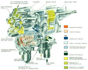
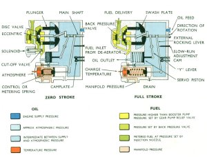
Rolls-Royce wanted to use the speed-density method of controlling the fuel-air ratio. It found that the Skinners Union carburetor division of the Morris group had already manufactured a reciprocating swash-plate pump, although it was much too small for the purpose. Rolls-Royce then invited SU to produce a larger pump of the same design, and to develop a control system for it with Rolls-Royce. SU engineers came to the Rolls-Royce plant, and received engine specific data of what the fuel supply produce under all operating conditions. The volume of fuel pumped with the SU swash plate pump can vary from no fuel to full fuel by changing the angle of the swash plate, similar to the method used to control the pitch of a helicopter's rotor blades. In the case of the fuel pump, intake and exhaust manifold pressure, intake manifold temperature and engine speed combine to control the swash plate angle.
Rolls-Royce later developed its own speed-density system that was mechanically simpler than the SU device. In the Rolls-Royce system, the feed pump supplied fuel at a constant pressure to two jets in parallel. A tapered needle valve operated by a pressure capsule measuring the pressure difference between the intake and exhaust manifolds controlled the size of one jet. The other jet was controlled a tapered needle valve connected to a temperature-sensitive device in the intake manifold. The fuel pressure drop across the pair of jets acted on one side of a flexible diaphragm that was loaded by the action of an engine-driven centrifugal governor on the other; the diaphragm operated a valve regulating fuel flow as the two forces balanced against one another on the diaphragm. Rolls-Royce was much more involved in the development of these speed-density systems than it had been in the development of float-type carburetors it used before.
Applications
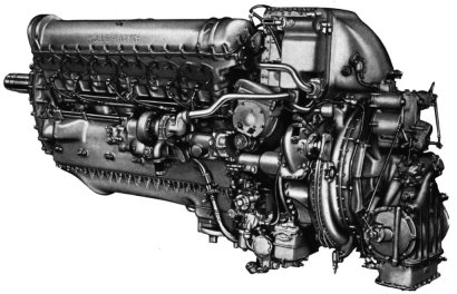
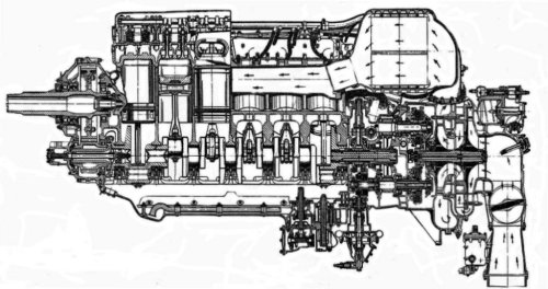
Successfully tested on a Merlin 66, the speed-density fuel metering system then became standard equipment on all following engine models. The Merlin 626 shown in Figures 97 ~ 98 was a commercial version used on civilian transcontinental aircraft.
 |
 |
| Fig. 97. Rolls-Royce Merlin 626 with Rolls-Royce Speed-Density System (left side) | Fig. 98. Rolls-Royce Merlin 626 Engine with Speed-Density Fuel Metering System (cross section) |
 |
 |
 |
| Fig. 99A. Rolls-Royce Speed-Density Fuel Injection Pump |
Fig. 99B. Rolls-Royce Speed-Density Fuel Injection Pump Schematic |
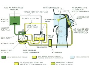
Fig. 99C. Rolls-Royce Speed-Density Engine Fuel System |
Bendix Stromberg Speed-Density Fuel Metering System
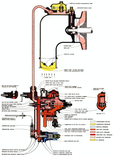 |
| Fig. 100. Bendix Stromberg SD Speed-Density Fuel Metering System |
Rolls-Royce needed a second source for injection pumps for Packard built Merlins that Britain purchased. Rolls-Royce selected the Bendix Company as the U.S. manufacturer, and handed the design over free of charge. In September of 1943, Bendix began development of a speed density unit similar to the Rolls-Royce "Governor Controlled Fuel Injector" for use on Packard-built Merlins.
The speed density system was also intended for use by the AAF on Packard-built V-1650-11 Merlin engines that was to power the P-51L airplanes. Bendix wanted a unit considerably more compact and lighter than the Bendix "expanding venturi" type ER-58A1 then under development. The ER-58A1 was essentially two carburetors in one that required moving components actuated at the time the two-speed Merlin shifted from low to high gears.
Rolls-Royce "Governor Controlled Fuel Injector" Serial No. 7 was received at the Army Air Forces (AAF) Wright Field Power Plant Laboratory on April 15, 1944 and bench tested through July 1944. Bendix reworked this unit, identified as Serial No. 7A and then installed on a V-1650-3 Merlin for tests. Bendix was redesigning the unit, adapting it to American production standards and methods. Bendix wanted to break the single unit apart into its functional sections, such as the temperature control, pressure unit, and accelerating pump, so that they could be individually calibrated and maintained.
The initial Bendix unit was the model SD-400A1 for the two-stage V-1650 Merlin. Serial Number S-3 was the first delivered to Wright Field for testing. Other units were tested on engines at Wright Field, Packard and by North American, including some flights in the P-51. A model SD-400C1 fuel control, Serial No. S-12 was then endurance tested on a V-1650-7X1 engine at the Aeroproducts engine test block in Vandalia, accumulating 408 hours.
The unit metered fuel to within ± 3%, increasing to about 5.5% rich at 400 hours. The most likely cause of the deterioration in performance was a damaged temperature probe. These early units had a nominal mixture ratio schedule in that there were no selectable settings equivalent to Auto-Rich and Auto-Lean.
A decision was made to use the Speed Density equipped V-1650-11 in the P-51L airplane, and it was necessary to provide Water Injection (ADI) for high power detonation control. The second-generation models incorporating this feature were the SD-400C2 and SD-400D25. A new "Water Regulator" was developed and integrated with the Speed Density Fuel Control.
Engineering and development delayed the production of an initial batch of 70 SD-400C2 units intended for the first batch of 50 P-51L airplanes that was scheduled for completion by September 1945. In June 1945, the decision was made to defer production of this first batch of production aircraft, engines and fuel controls until January 1946.
Development of the SD-400C2 fuel control was not completed prior to the end of hostilities in August 1945, which resulted in the immediate termination of production contracts for the V-1650-11 and the P-51L. Development work did continue on the V-1650-11 until October 1945. Following the third unsuccessful attempt to run a 50-hour preliminary flight-rating test, the program was terminated.
A recommendation was generated for further development of the speed-density type carburetor, similar to the SD-400C2, for other AAF aircraft engines able to utilize the advantages of the speed-density method of fuel metering. On October 8, 1945, the AAF established the designations for the SD-400 equipped Allison V-1710-143/145 engine for the P-82E/F.
The initial Bendix speed-density fuel metering system unit was the experimental model SD-400A1 intended for the two-stage V-1650 Merlin. Other units tested at Wright Field, on engines from Packard and North American, including some flights in the P-51. A model SD-400C1 fuel control was endurance tested on a V-1650-7X1 engine at the Aeroproducts engine test block. The SD-400 did not hold a constant fuel-air ratio through the cruise range, and became somewhat lean at high power settings.
When the decision was made to use the speed-density equipped V-1650-11 in the P-51L airplane, it became necessary to include an ADI system to control detonation, leaning the mixture when ADI fluid was flowing. The SD-400C2 and SD-400D25 units included an ADI system.
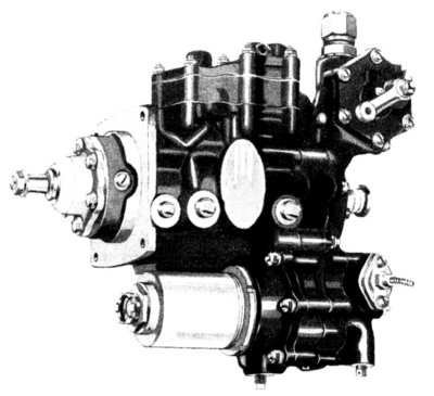 |
| Fig. 101. Bendix Stromberg Speed-Density Fuel Metering System Control |
Applications
| SD-400A1 | PACKARD EXPERIMENTAL |
| SD-400B1 | ALLISON EXPERIMENTAL, W. A. C. EXPERIMENTAL |
| SD-400C1 | Ranger V-770, Packard V-1650-11, Merlin 301, 300 |
| SD-400C2 | V-1650-11,-21 |
| SD-400D1 | R-1820-56, ALLISON EXPERIMENTAL |
| SD-400D2 | PACKARD EXPERIMENTAL |
| SD-400D3 | V-1710-143 (G6R), -145 (G6L), -G9 |
| SD-800A1 | WRIGHT AERO EXPERIMENTAL |
| Fig. 102. Bendix Stromberg Speed-Density Fuel Metering System Applications | |